


Kevin-the-lubber
-
Posts
1,232 -
Joined
-
Last visited
Content Type
Profiles
Forums
Gallery
Events
Everything posted by Kevin-the-lubber
-
 All of those items look straightforward apart from the chain. This is perfectly do-able, just twist it through 45 degrees so you can get all the necessary supports, and make sure there's sufficient clearance between the links to avoid bridging. I'd recommend downloading the Lychee slicer too. It's free and better than Chitubox when support placement is finicky as it has various options around support visibility. It also allows you to mirror support placement which saves time when you have regular shapes.
- 454 replies
-
- 1
-

-
- Union Steamship Company
- Stepcraft 840
- (and 3 more)
-
Downloaded now Richard, thanks. From a first look and general modelling perspective there doesn't seem to be too much difference, does there and as I don't have the Jordan plan and the Campbell plans are clear, I'll use these as the reference. The overnight print of two full deck sections was equally successful so I'll revisit making a scratch deck and furniture from Campbell, but use whatever I can of the kit. Or do both actually, since I'm halfway through painting the revell deck, and just see which I like most. This test is a bit rough'n'ready, with more care in glueing the planks would all sit dead flat, but I just wanted to see how it would sand and look with rattle-can primer (still wet here!) and avoid getting it stuck to my workmat, so didn't pay too much attention. Probably need to start using the thick, slower setting CA for things like these. I haven't done much filament printing for many months and I imagine the PETG has a bit of moisture in it now (it's quite hydroscopic), so there was some lifting at the outer edges (losing adhesion to the build plate) which should be easy to correct after cooking the filament for a few hours. When I do this for real I'll may stick it to a backing sheet of 1mm evergreen. It proves the possibility though, that I can get a good planking effect and maintain dimensional integrity at full model size and, with some light sanding, get a quite acceptable top finish. So, next job, design the planking pattern a bit more true to life including margin planks around the hatches etc. Meanwhile, time to re-make the pin rails and some very small deadeyes. I'm thinking I might cut out the gussets in the revell hull and the rest of the pinrail where it extends back into the poop deck, make these integral to the new pin rail, to give some support; even though the gussets aren't true to the CS, they're a sensible alternative at this scale. Kind of wish I hadn't already glued the hull together now, this would have been easier as two halves.
.JPG.bf0da07d901e87d8e941676a03fd507d.JPG)
- 444 replies
-
- 4
-
-
- Cutty Sark
- Revell
- (and 2 more)
-
I second Greg's suggestion, but I would keep short shafts, maybe a couple of mm long, make a drilling template (100 holes or so) and drill guide holes to the right depth in the hull. It'll be miles easier locating the rivets in holes than on a surface and you can use the last holes as locators for the next sequence so they are all nicely aligned. And if you really want to, you could probably get an interference fit so you don't even need to use any glue. Otherwise, I'd try a 0.8 shaft for a 1mm hole or 0.6 to 0.8 if the head isn't covering the hole well enough. The belay pins below have 0.6mm shafts, these are on a single support, which works fine, so either approach should be okay. (The bending on some is because I haven't stored them upright, something must have been leaning on them). You should be able to do blocks of maybe 300 or 400 at a time, just leave a gap of about 1mm between them to ensure there's no bridging and, as Greg says, don't get too greedy 're filling the build plate. Me, I'd go for about 50% occupancy tops. Also, nudge the stl a little on the plate for each print run. You'll get little dinks in the FEP when doing these as you're repeatedly pulling on tiny spots and it's better to vary that a bit. Re' weld seams, do-able but may be tricky. The width is okay : I imagine the butt welds are about 20mm - 30mm wide so 0.6mm - 1mm at 1:35, plenty wide enough for resin printing, I've printed the equivalent at 0.3mm without any real issue; but the welds wouldn't protrude that much from the hull surface, probably no more than 3 or 4 mm, which scaled is only about 0.1mm i.e. 2 print layers. The biggest challenge may be getting the strips off the build plate but glue-ing them on could be fun as well. I think I'd instead look at whether I could run a tiny bead of epoxy glue down the line and press a pattern into the surface when it's near-dry but still soft, or something like that.
.JPG.45c347c806d8cb5ee6598973688d865c.JPG)
- 454 replies
-
- 4
-
-
- Union Steamship Company
- Stepcraft 840
- (and 3 more)
-
I have high quality campbell plans and loads of graphics software so I’m sure at least one of them can handle .psd’s. I’ve noticed more and more variances today, the Campbell pin rails are much slimmer in the fat part than revell and as I’m going to remake these entirely it would be good to have a reliable source.
- 444 replies
-
- 3
-
-
- Cutty Sark
- Revell
- (and 2 more)
-
This is why I was reluctant to start a build log; like a little jack russell I find it very difficult to walk past rabbit holes. A quick, small experiment this morning, printing a section of deck joint using a filament printer; Pretty acceptable, don't you think? Much much better than I was expecting. Scale-wise, the planks are 2mm wide, the seams are 0.3mm. The join is exactly what I was aiming for, nice and snug. I haven't even glued these two parts together, that's how nicely they sit. This is with a standard 0.4mm nozzle, I could get a finer top finish if I dropped down to a 0.2mm, though I quite like the grain; it's not really wood-like but nevertheless gives some texture. The black is another experiment. I found a little tub of graphite powder in our gigantic 'making' drawer a few days back, tried brushing that into the grooves and grain. The thicker line is inked. I think I almost prefer the graphite. Now, since filament printing solves other resin problems - e.g. the rigidity of the deck, in this instance needing no further support other than perhaps a lap strip under the joint; and no post printing shrinkage or curling - I have two full sections printing away. They'll take around 12 hours, but if they come out as hoped, I may yet swerve towards my own deck and positioning/sizing the furniture closer to Campbell's plan. The only down side is that this material is hard to sand, tends to go furry, but I guess I could also look at a very thin coat of filler or, for that matter, prime heavily and sand smooth.
.JPG.fec37b2d82271dcca9db732ad938d3cc.JPG)
- 444 replies
-
- 3
-
-
- Cutty Sark
- Revell
- (and 2 more)
-
Richard, any knowledge on the dimensional accuracy of Campbell's plans? I've loaded & calibrated them as close as poss' to a measured revell plan (which seems closer to 1:100 than 1:96) but noticed quite a lot of variance on much of the deck furniture, both in size and position. The deckhouses are much, smaller on Campbell and the foredeck extends about 3 feet further aft. While what I know about seafaring wouldn't even fill the proverbial postage stamp, I've once or twice thought that the deck looked a bit tight for space for moving around and Campbell makes far more sense.
- 444 replies
-
- 2
-
-
- Cutty Sark
- Revell
- (and 2 more)
-
Just had a look online at your CNC. The world is your oyster with that machine, if you wanted to shell out for additional tooling I.e. a print head, presumably for filament, plotter, engraver etc. My memory may be playing tricks but I’m fairly sure we used to mill and turn styrene back in one of the places I worked, when whatever machine we were building needed something like a fixed inspection window. Just a question of getting the cutting and travel speeds right. And, to go off topic, you could make and sell some nice after-market scale decks with that thing….
- 454 replies
-
- 1
-
-
- Union Steamship Company
- Stepcraft 840
- (and 3 more)
-
Bill, I hadn’t realised you could varnish between coats, I’ll try that, but will give the sand coat a couple of days to fully dry first. I imagine it also gives you a slight chance to quickly wipe off any mistakes. On my first attempt I used a 0.2 pen and was quite disappointed at how ‘fuzzy’ the lines looked, which makes sense now and, hopefully, won’t happen with a coat of varnish. But I’ll also try a thinner pen this time.
- 444 replies
-
- 3
-
-
- Cutty Sark
- Revell
- (and 2 more)
-
Hi Bruma, yours beautiful example is another log that I’ll use as a major reference and, if it’s okay, I’d like to come back to you soon for more detail on the pin rails. OC, yes, I have to have a go at doing my own shrouds. I fully expect to get bogged down a bit on the rigging as I’ve never done more than tie a few bits of cotton with granny knots back in my childhood. The resin work on this kit is really easy which makes it fun, and my impression is that the masts and yards are quite a bit stronger than hellers so probably don’t need beefing up so much.
- 444 replies
-
- 3
-
-
- Cutty Sark
- Revell
- (and 2 more)
-
No, please carry on, it's all useful info for later, so long as it doesn't bother you too much seeing me blithely do my own thing! That exposed deck would have been 7th heaven for me, I loved working on heavy steelwork. My party trick was creating accurately curved RSJ's of this size using heat and water, got taught it by an old boy when I was a young apprentice and never got tired of doing it.
- 444 replies
-
- 3
-
-

-
- Cutty Sark
- Revell
- (and 2 more)
-
Ah, now I understand. I thought you were talking about the width of the planks and that neither revell nor scaledecks were accurate in the number of boards across the deck. On my test deck I based the fixing distance on where I wanted to split the deck, which was as far as possible coincident with the fore or aft hatch edges, to minimise the number of joins. And then equidistant fake joints inbetween the splits. All of which was based on the limitations of my resin printer and not in the least connected to the real ship. One of my conclusions is that I would need to filament print supporting beams to go underneath a 2mm resin deck, in order to hold the cross-deck curve. In fact, it would probably end up looking quite similar to the real thing. The reason for filament printing these is that, using e.g. PLA or PETG, I'd get a pretty rigid object whereas anything this small would be too bendy or brittle in resin. It did occur to me that I could of course print a beams framework and individual planks and glue them up - a POF in fact, but out of plastic; but then thought, why would you do that rather than just use wood? Which is why I've parked this - there are all sorts of interesting directions for experimentation, but I want a ship on my windowsill goddammit, and soon 🤪.
- 444 replies
-
- 4
-
-

-
- Cutty Sark
- Revell
- (and 2 more)
-
No, I didn't know that. I don't think I ever worked in muntz; plenty of copper, brass (beautiful material to work) and esoteric aerospace stuff but not that. So, while my reasons for blending a bit of gold, copper and brass are aesthetic, it'll be on the right track anyway.
- 444 replies
-
- 3
-
-
- Cutty Sark
- Revell
- (and 2 more)
-
Hi Richard, I did and quite quickly decided against it. I bought this kit fairly cheaply off ebay and, if I bought all the goodies, I'd spend two or three times as much on those than the cost of the kit itself and probably still not get a result that warranted that much expenditure. This build is all about doing it fairly quickly, without trying too hard, getting a feel for the CS with a view to a more serious build down the line. For instance, my remakes of the deck furniture are just quick'n'dirty remakes of the kit parts, rather than researching what they should look like. Can you explain this a bit more: "exactly 2 spans long and 7 along forward deckhouse"? I'd quite like that deck plan too, not so much for now but for further experimentation. Obviously I made one based on the revell kit, which looks the part, but if I do find a printing solution I might as well print it true to life.
- 444 replies
-
- 3
-
-
- Cutty Sark
- Revell
- (and 2 more)
-
Glad you're here Bill, I'll be bound to have questions, and here's the first. Did you airbrush the wood washes or hand-brush? Base coat laid this evening, went on like a dream, think I'm starting to get the hang of this air-brushing business now. I'm itching to paint the copper on the hull, I bought the vallejo metals set and messing around on scrap with a mix of copper, gold and bronze gave some lovely colours, with an emerald green wash on top. It's all glued up and primed, but I must sort out the pin rails first and maybe also the fore and aft railings. It looks like you left these until after you'd painted, did it make any difference? I've also bought the hismodel etch name plates and decor as the decals were damaged, waiting for those arrive. I needed to cut out the 'bump rail'(?) on the stern as there was a lot of misalignment, but fortunately found some half-round evergreen in my materials stash which, after a little sanding, blended in very nicely.
.JPG.e67b28640279677ff0b75ee297ed8072.JPG)
- 444 replies
-
- 4
-
-
- Cutty Sark
- Revell
- (and 2 more)
-
It's even more fun driving it! If you ever get the chance, take one up the Llangollen canal; it's beautiful all the way but the Pontcysyllte aqueduct is a very, very unique experience. Bear in mind that, as an ex-mountaineer, heights don't bother me too much but I was utterly petrified taking a boat across this thing. No guard rail on the far side, lean out and you're looking straight down. Never have I steered such a straight line and winced at every little brush against the side. ps. can we have some of your snow please, when it comes back

-
I think the major thing is less the time-saving nor the mistakes-avoided, though both are invaluable; it's that most of us will build at least a marginally better model through shared knowledge and some (like me, I hope) something way, way better. If I hadn't found this (and previously, Pete Coleman's) site I would have probably finished glueing plastic and painting (badly, with one brush and half a dozen pots of enamel) within a couple of months and then, on seeing a predictably poor example, decided to not even bother with rigging. Or just thought the instructions were too vague and quit because of that. I know mine will still take me years to build but that's partly because this site shows what's possible with patience and care, and, more importantly what patience and care look like in the modelling world. And then there's the fellowship. I really like that nowhere on this site do you see anything other than friendly interest, encouragement and helpfulness, never a 'superior' comment. ps. The biggest thing I've ever sailed is a canal boat (aka narrowboat), don't know if you have these in the states but my ambition is to buy one when I retire in another year or two and spend the next two or three years exploring the country, bit by bit, via the canal system.
-
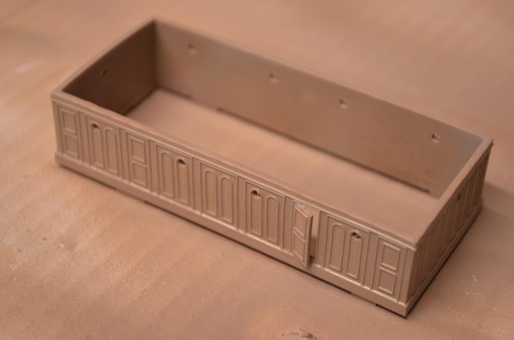
nb. I should have mentioned, that deckhouse is a printed version, so you can see what I mean that the revell parts are actually pretty damn good. To be honest I only made this because it looked like fun to do and it's so much easier having it as a single piece. Plus the roof gets negative plank lines.
- 444 replies
-
- 5
-
-
- Cutty Sark
- Revell
- (and 2 more)
-
Thanks Ian. Yes, I'll settle for that, the good thing about making cock-ups is that sometimes you do it better second time round. Go on, join the club, put her back into the dry dock.
- 444 replies
-
- 3
-
-
- Cutty Sark
- Revell
- (and 2 more)
-
Thanks for the additional pics Bill, my log is up now. That's quite a result you've got on the masts lining up, I can tell from here, with a tradesmans' practised eye, that they are absolutely true. I'll be watching these next stages with particular interest as the rigging stage terrifies me, but also because I don't think I can live with the revell mouldings for the CS ratlines.
-
I’m trying the Vallejo ‘Old & New Wood’ paint set used by Bill as I really like that look. Air-brushing has still been a bit hit and miss with clogging mid-spray. Thinning solves it but I think I’ve been over-thinning the Vallejo model air paints and what works best is the plain paint plus a few drops of flow improver. 5/1/22 Morning: Inked in most of the plank lines. Really difficult to pick out the moulded lines to follow and if I’m honest, it looks like the shipwrights used whatever old planks were knocking around, some a bit wide, others a bit thin. Evening: stripped the deck back to bare plastic with Isopropyl Alcohol and a tooth brush. Much easier than expected, not something I’d be fearful of next time. And strangely satisfying. What a pig’s ear I made of those lines. I don’t know why I thought I could just follow the near invisible moulding, why I didn’t make a little template. 6/1/22 Took advantage of needing to start again to sand off the lumps on the deck for locating the sail lockers and the two little strips under the fore winch which make no sense at all. Bracing rods on these kinds of machines are invariably a few inches up the legs. Neither bits are necessary and just make inking the plank lines more difficult. Undercoating again, along with the fore deckhouse, hopefully better this time, now that I have a formula for avoiding the air-brush clogging.
- 444 replies
-
- 7
-
-
- Cutty Sark
- Revell
- (and 2 more)
-
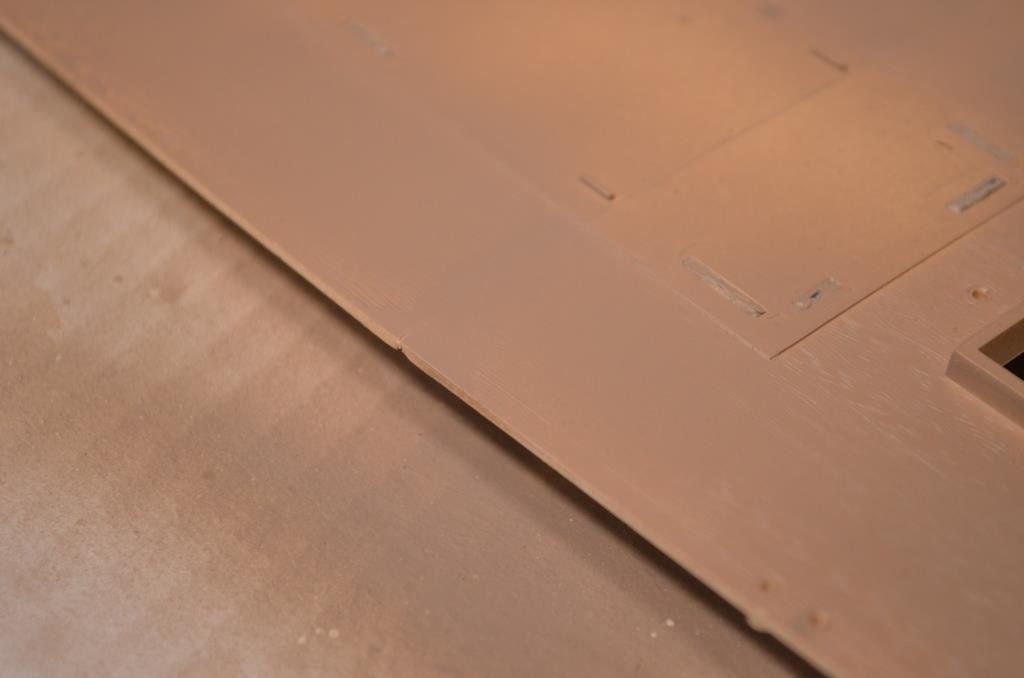
I’m set on this not becoming another Victory stern, where I spend months and months solving a single problem rather than having fun with the kit, so I’ve more or less abandoned the idea of a DIY printed deck, in part because there would be other engineering problems to resolve even if I did get it printed – at 2mm thick an object of this size will curl post-printing and would need reinforcing on the back. I switched to the kit deck and blending the joints by filing a chamfer on each part then filling and sanding. What I’ve ended up with is reasonable, hard to be sure if it makes much difference until the painting is finished but this is what they look like primed. (I've masked the deckhouse slots with blutak to stop paint building up in these and other key location holes).
- 444 replies
-
- 7
-
-
- Cutty Sark
- Revell
- (and 2 more)
-
As many will know, in their wisdom Revell split the main deck into three parts, making for seams across the middle. This is typical of the kit in some ways, there’s no apparent logic to the splitting of some items. Thus we have separate fore and aft railing sections while built-in along the sides, with more ugly seams and flash to deal with rather than a continuous rail and a bunch of stanchions that need to be glued (the logical approach); likewise a series of pin rails when one long rail would give a better modelling outcome. This is a shame in my view, because the detail quality is generally very good and, if the kit was cut logically it would be a dream to build and yield a good result in most hands. The deck joints bothered me, along with the positive plank lines. I don’t want to spend £70 on a laser cut wood top because this build is just for fun and learning. So I spent about a week experimenting with making a resin printed deck instead. Drafting the model in 3D was straightforward, probably only took 2 or 3 hours. Printing was more troublesome. The idea was to do ‘jigsaw’ joints, following the line of staggered plank ends and make it in 3 or 4 sections due to machine limitations. However, for reasons I don’t yet fully understand, I could not get the joint edges to print true to the design, they keep coming out with a gentle curve across the end such that the joint gets more and more gappy. The photo shows what I mean. I know what’s happening – the curing of each layer is causing microscopic shrinkage that pulls the edges towards the centre – but not how to prevent it. I’ve tried various permutations both design-wise and printing-wise without success. Even looked at whether I could get the deck printed as one piece by a commercial outfit, but it’s too big for anything other than exotic industrial machinery. There are probably a few more different ways I could try to get this printing true; one of them is to at least give it a go on the filament printer, but I’m not too optimistic about this being accurate enough.
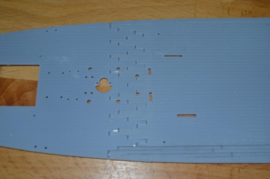
- 444 replies
-
- 6
-

-
-
- Cutty Sark
- Revell
- (and 2 more)
