


Kevin-the-lubber
-
Posts
1,232 -
Joined
-
Last visited
Content Type
Profiles
Forums
Gallery
Events
Everything posted by Kevin-the-lubber
-
 Couldn't agree more. I couldn't find walnut at the art shop so got some windsor & newton peat brown and nut brown, think peat is the darker of the two, which is what I've used so far. I especially like the way it 'spots' and settles into the slightest surface blemish, creating an illusion of texture. I'll try the lighter colour when I paint the roofs white, see if that picks out the plank lines without making the rest muddy.
- 444 replies
-
- 1
-

-
- Cutty Sark
- Revell
- (and 2 more)
-
Rob, is that a Glory plan in the background and, if so, where could I get that? Since starting the Cutty I'm taken by the beauty of clippers and the Glory in particular, and fancy this being the one where I perhaps try to model it entirely for 3D printing. I love those masts, such an interesting profile.
- 3,560 replies
-
- 1
-
-
- clipper
- hull model
- (and 2 more)
-
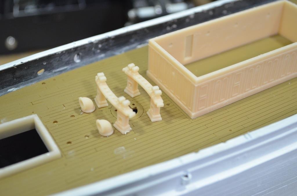
Having got the deck sorted out I've started working my way through the furniture. Originally I only intended to remake those parts which weren't so good in the kit but so far I've only used the hull! This is in part because Revell use a lot of half rounds for location pins, to stop us putting things on back to front, whereas printed parts usually need holes reamed out to size and it's as easy to remake the part as mess around filing. I'm sure I'll still use some of the fiddly bits though. In the end I went for printing the deck flat on the FDM printer in the background as this gave the most satisfactory plank lines. All the pink stuff is resin printed, anything brown is filament. Horses for courses, and I've regained an appreciation of FDM. It certainly has it's place. I think there are probably enough shaped objects on the deck to pull it to the slight curved shape (it goes quite easily) but if not, I'll put some FDM printed curved beams underneath. The final photo is my first practice at weathering on a test print. I like this colouring, I know it's not at all true to life but it floats my boat. I silently thanked Marc many times for the inking tip, such a good medium for giving light and shade and so forgiving. Neither am I being too religious about accuracy or fidelity regarding the parts. I've made the aft cabin portholes a little larger, likewise the skylight panes, just 'cos it's my model and I'll jolly well do whatever I like 🙂. Once all the deck work is done I may think about some furnishings for the cabins, since I've opened the doors, and a false lower deck with something interesting down there, for depth and interest, leaving the hatch covers off.
.JPG.1b60f663c02bcc7dabd80b651cf26c3f.JPG)
- 444 replies
-
- 6
-
-
- Cutty Sark
- Revell
- (and 2 more)
-
Meshmixer... you're doing better than me, that programme is still a dark art to me. But apparently very very good when you know how to use it. These were a very simple and quick job in F360, it honestly only took about 10 or 15 minutes, so if Meshmixer doesn't give you what you want I'll happily modify at this end. Just post a sketch or message me.
- 321 replies
-
- 5
-
-
- Finished
- Flower-class
- (and 1 more)
-
I'm easily distracted.... and a bit bored with what I'm doing today 🙂. You should be able to print these in FDM, probably want to put some supports for the side holes. I have no idea what these look like in the flesh so did one with a bottom, one without, and the F360 file is there too in case you have someone to tweak it. smoke float.zip
- 321 replies
-
- 7
-
-
- Finished
- Flower-class
- (and 1 more)
-
Yes Bill, it works well. I've fiddled around with it over the last week or two, to see what works best i.e. line width, built in curve or flat and curve it with beams underneath afterwards, and settled on the latter the other day.
- 444 replies
-
- 1
-
-
- Cutty Sark
- Revell
- (and 2 more)
-
Now I know what you mean. Nicely spotted.
-
That's mighty impressive metalwork to do by hand, and this is coming from a former precision metalworker. If I saw that in the flesh I would believe it to have been bought, and expensively so. I'm still struggling to figure out what a metal folder tab is though. I can't think of anything from a filing cabinet etc that fits the bill.
- 3,560 replies
-
- 1
-
-
- clipper
- hull model
- (and 2 more)
-
That would make sense. Good luck with the next attempt. It seems ironic that these fantastic tech developments land in our lap but we are immediately pushing at their limits. I hardly ever seem to have something that is just 'mouse click, mouse click, mouse click', done.
-
I'm equally lazy about leaving resin in the tank in between printing sessions though not for months! I just give it a good stir and hope for the best. I rarely have sticking failures these days except where it is entirely my own fault i.e. over-optimistic supporting or object orientation, and I put this down to the resin being good and just using the recommended settings rather than messing around with these. I've only done one print with the anycubic resin and found the result horrible, very similar to my one experiment with the elegoo water washable; poor surface finish compared to the elegoo ABS and sirayatech. But that may be that I didn't change my settings so I will give it a better test presently, otherwise I'll have to slowly use it up by adding a tiny bit of it to other resins over the next few months, bit by bit. Far too expensive to just throw away! For your parts I would probably happily use elegoo ABS as the curling only really becomes an issue on bigger parts - all of my victory stern parts were printed using the elegoo abs, though when I go back to it I'll also try the transom and quarter gallery bodies in siraya, as curling remains a bit of a problem and non abs is too brittle. For what it's worth, the window bars on my stern are 0.3 and I use medium supports around the frame and thin on the bars, but I do have the advantage that they cross over in the middle so have a bit more support. But, if I remember rightly, the wispy decor on the lower counter is only 0.2 and I also supported this. getting the supports off without breaking the part is the hard bit. I make the supports quite long, about 10 mm, and snip them at the bottom, then tease them off the part. Oh yes, I've also learned that with very delicate parts it can be better to leave them to dry out for a day or two after washing, and then cure. That seems to result in less curling. And clearance is essential, as you know - the slightest interference will make small bits bow. One possible thought; if they warp after printing this would only be that the frame is shrinking very slightly; maybe you could either restrain it during drying, or pull it back when glue-ing in place?
-
Daniel, how thin are the bars? I've been experimenting a bit with resins last month as I've only ever used Elegoo ABS over the last year and, good as it is, it does tend to warp post-printing. Recently I've been using SirayaTech Fast, which is more or less the same price, and I like it a lot. Much less warping and not as brittle as Elegoo Standard. And much, much nicer than Anycubic standard. May be worth a try if you haven't already.
-
That's the thing. Give me a drawing, even a bad one, and I can see the end object. Give me a piece of wood and I see... a log for the fire? Astro photography... been wondering whether to go in that direction. The eyes alone just aren't good enough now, even with one each of a fairly decent 6" refractor and 6" reflector. Though I don't like the cold that much anymore, nor staying awake until the small hours. Hence modelling 🙂
- 3,560 replies
-
- 1
-
-
- clipper
- hull model
- (and 2 more)
-
For the likes of me, who lack the patience, skills and confidence to do what you do, 3D is a godsend. But I can tell you with absolute certainty that I got far more pleasure and satisfaction when I used to make bigger things, like garden furniture, cabinets etc, the traditional way, especially if it involved a bit of creative recycling. That’s not to say I don’t enjoy the 3D side at all, far from it, but it’s not the same.
- 3,560 replies
-
- 2
-
-
- clipper
- hull model
- (and 2 more)
-
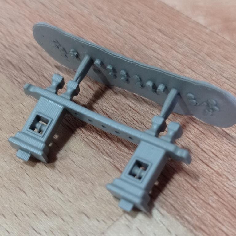
I'm always hugely impressed by you craftspeople who do this by hand, I certainly couldn't and I suspect that, well done, it gives a better end result than other methods. But, I'm not so sure that statement is true any more, with 3D printing becoming so popular. Small example below, which is at 1/96; this took me around 20 minutes on the computer. It probably takes about an hour to print, but I can print a whole load of other things simultaneously; and if I get it a little wrong or just don't like it, I can tweak the design or re-print in a few minutes. Is it as rewarding, satisfying? I don't really know as I haven't yet built a wood model, let alone a scratch build ship. I suspect not. (The strange top bit is the printing support, like a sprue, left on while painting) I absolutely love this model, by the way. Elegant, statuesque are words that spring to mind. When I read that you'd previously used the revell cutty sark as a base for an earlier one, for a nanosecond I thought oooh, as I'm still early enough in mine of the same to look at that, but quickly reined that daft thought in. So I'll just pull up a chair, join the audience and enjoy reading the remaining 79 pages.
- 3,560 replies
-
- 3
-
-

-
- clipper
- hull model
- (and 2 more)
-
What an interesting and fun project. It was mainly the O’Brien books that inspired me to start modelling again, some sort of late middle-age crisis/homage. I can’t offer a shred of knowledge here, even about the book series, which I’ve read twice, as I have the memory of a goldfish. But I’ll enjoy seeing it develop and the lively discourse around details that mostly go straight over my head!
- 341 replies
-
- 3
-
-
- Sophie
- Vanguard Models
- (and 1 more)
-
Things of beauty nonetheless. Those deck plates in the second photo - that was what I was talking about many posts back.
- 454 replies
-
- 2
-
-
- Union Steamship Company
- Stepcraft 840
- (and 3 more)
-
Wow, I don't think I've ever seen any structure with that much welding distortion! I think you're right to knock that back a bit.
- 454 replies
-
- 2
-
-
- Union Steamship Company
- Stepcraft 840
- (and 3 more)
-
Very impressive model Yves. A bit late now, but I’ve had good results FDM printing a planked deck for my Cutty Sark by designing in the lines with a 0.2 width x 0.3 depth. That is also quite tedious but probably less so than laying a floor, though I think yours may ultimately look better.
- 321 replies
-
- 5
-
-
- Finished
- Flower-class
- (and 1 more)
-
I probably should have made it my first to begin with, it's a little easier than the Victory, so long as I don't go too mad with remakes. The range of ships in this scale is a bit limited, isn't it, and whatever you go for first you're likely to end up with a few challenges.
-
What a sad, sorry sight - the photo, that is. It’ll be at the least hugely entertaining watching what you do here Daniel. I sense experiments with drinking straws ahead 🙂.
-
Oh good, glad some of them are proving useful. I’ll recycle the files for the CS. By the time I get back to the Victory I’ll probably have added to the collection, like you I hadn’t even heard of thimbles. I think for ultra-small sizes you’re probably better off with wood anyway and I can see myself buying these. I bought the stern decoration for CS from Hismodel a couple of weeks back and he included some samples of his tiny deadeyes, which are works of art. In a similar vein, I saw some Cornwall model boat brass stanchions and other parts at the weekend which were also impressive.
-
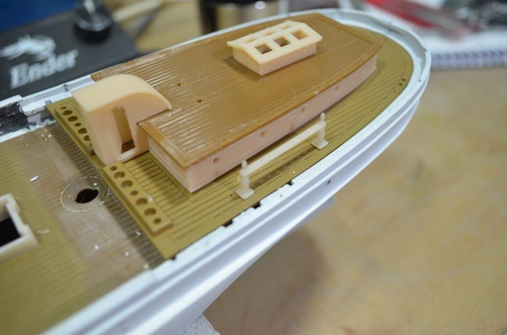
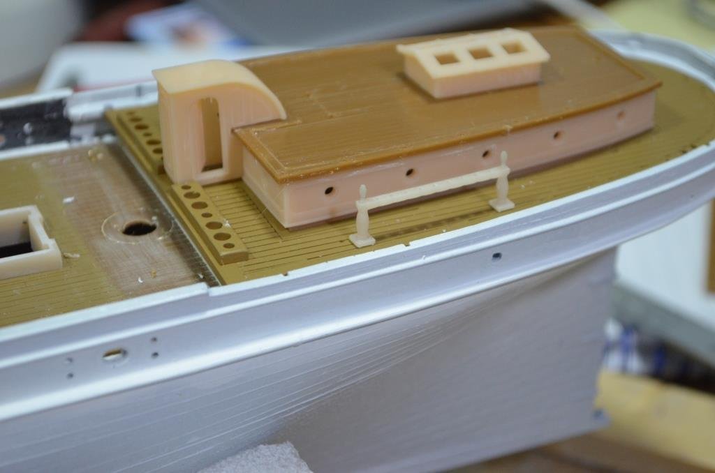
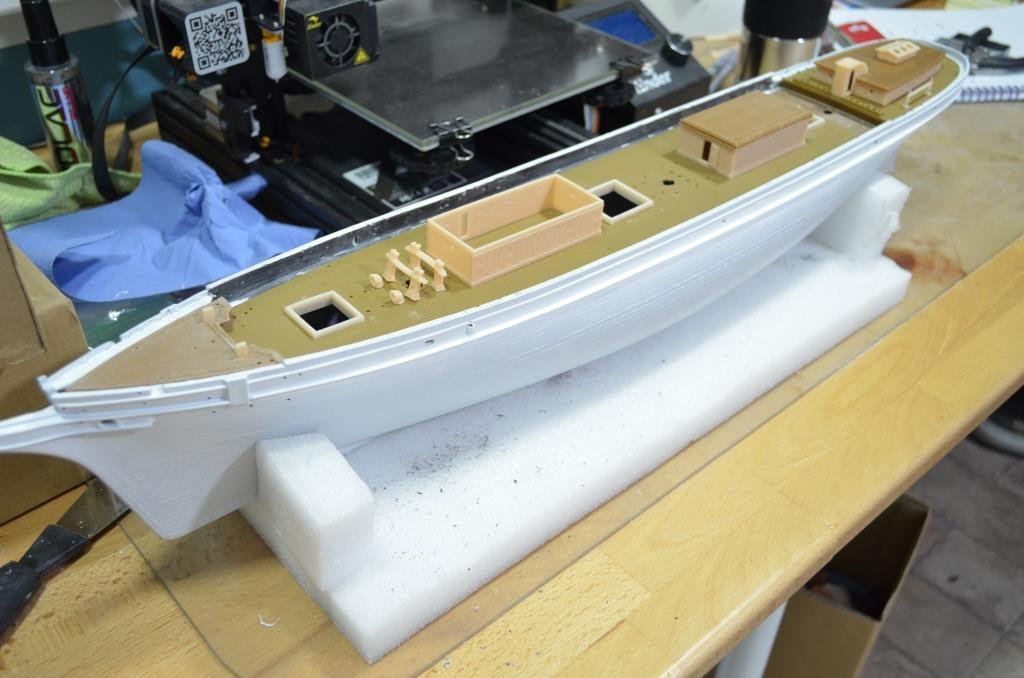
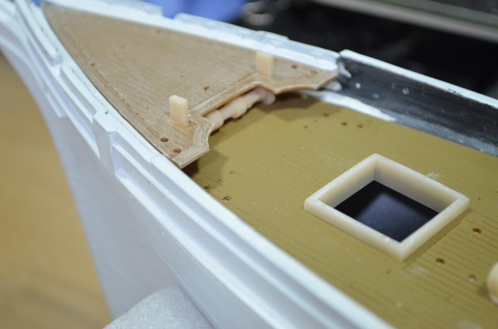
Over the last couple of weeks I've been tinkering with printing a new deck with disguised joints and negative plank lines, and pinrails with some embellishments. The latter will be for it's own update as and when I'm there. For now, the deck, which is printed on a filament printer. I wanted to see if it was worth the effort of remaking this, bearing in mind the kit part (top of first picture) has come out reasonably well so far. So, printed in 5 pieces; the 4 you see here, and a quarterdeck (work in progress). The bowsprit socket is printed separately in resin; although the top of the deck has an elliptical profile (thanks Richard) the bottom is flat and, by making all the protruding parts separately, this is easy to print and sand. A bit slow though - the bigger sections take about 6 hours each to print. The white card is 0.5mm evergreen and the sections are glued to this as well as each other using CA. This is to ensure the bottoms of the sections are perfectly aligned, thus making the top also aligned. These sections slot together very nicely, no undue play nor tightness and only a little bit of post-printing cleanup of the joints required. The radial lines you see are layer lines, as the thickness varies along the centreline but is constant at the edges. Trial fit. Not bad. some slight 'air' at the prow which I may or may not improve on. As it's hidden by the foredeck it doesn't matter. The quarterdeck needed more work, what you see here is a new profile sat on top of the test piece as this was very gappy. I've needed to make it about 2 or 3 mm longer and it will now be nearer the Campbell plans than Revell and I'll remake all the furniture (which I'd probably have done anyway). The monster clamp isn't there for force, it was just what was to hand to lightly squeeze the hull so I could get true profile measurements! The pink strip is the WIP pin rail, you can see the butchery to the inner hull where I've removed all the interior mouldings. Pity I'd started painting! A few pics now of it sanded smooth. I used my normal woodwork orbital sander just to see whether this destroyed the plank lines as these are only 0.3mm deep, but it was fine. PTEG is tough material! The joint lines between the foremast and hatch are a real joint. I haven't washed out the dust from sanding yet, it gives a good indication of what it should look like after painting and inking in the lines. The joint lines are almost indistinguishable from the others in the picture, which are just 0.2mm wide printed grooves. Clearly this is still well out of scale but, at scale, the lines would be near invisible. (Note to self, to move the joints on the margin planks by a few mm, and make them look like the other plank ends: it will disguise them better). same here across the fore cabin: the line across this will be hidden by the cabin All told I'm pleased with how this is shaping up and will go with the replacement deck. It's really not very much work in itself and I'd already started remaking much of the deck furniture. So, drifting away from the 'build out of the box' but happily so.
.JPG.249f1cd0523d25b3de6271618c9f8773.JPG)
.JPG.378df39c90dd55061ad624e152eaa8be.JPG)
.thumb.JPG.94e13eb3ed73e9af2f5a98580a5dda60.JPG)
.JPG.6084f1371b557070ab5da5f8c4770a76.JPG)
.JPG.0253d837b2c8d1a39bcb18ae993e83a8.JPG)
- 444 replies
-
- 7
-
-
- Cutty Sark
- Revell
- (and 2 more)
-
Bill, I keep meaning to ask, now that you're in the thick of rigging, were those blocks any good? I really won't be in the least offended if you said no or they are a complete PITA. I mostly want to know because I'm quite close to having to attach my own deadeyes to my new pin rails on the CS and if it turns out they fail or have other big shortcomings, better that I know now. I'm having a lot of fun with the CS. New deck trials have gone really well, same with pin rails etc. I'll post about it again soon but, unsurprisingly, I'm ending up spending a lot longer on it than planned. I guess that's inevitable when every step is a learning exercise. I still wouldn't know a gusset from a gannet though. My but you're making strides on the rigging, and it lifts the model so much, doesn't it.
-
I bought my kit about 10 years back and the quality of the pressings is/was pretty good, very little flash, few sinkholes and good detail. The issue with the deadeyes is the design rather than moulding, they don’t have a groove around the edge for rope to sit in. The wood grain is always going to be debatable, at this scale it would be invisible and people often sand this back on the hull especially. On the whole I’d say it’s a much better quality kit that the revell Cutty Sark and is holding up well. That said, it would be a shame for them to retool exactly as is. They could lift the kit up to ‘superb’ by redesigning a few bits. Though maybe that would take all the fun out of it!
-
If I can digress slightly, I needed to get out of the house today after being cooped up in my home office all week, so went to the only surviving model shop in this area, Sussex Model shop in Worthing. Always a pleasure, a veritable Aladdins cave and pleasingly very, very busy. Anyway, I had a quick look at one of the Tamiya 1/350 warships as the box was open. Really impressive detail and crispness and no flash. It's a shame they don't seem to make any age of sail models.
.JPG.cb81d6fe5e4763f58b3539a71d5f2612.JPG)