


Kevin-the-lubber
-
Posts
1,232 -
Joined
-
Last visited
Content Type
Profiles
Forums
Gallery
Events
Everything posted by Kevin-the-lubber
-
 I may have a look at that (mod podge). Presently I'll be experimenting again with the window panes and, while I have some acetate sheet as a backup I'm keen to see how far I can go with resin printing. Thickness-wise, I'm comfortably printing at 0.2mm thick, but those parts are horribly fragile. Here's another thought, arising from my windows fallback plan - what about the package being geared to producing cutting and forming templates, for acetate parts?
 -
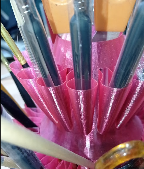
I'm not so sure about that Rick. This is my paintbrush caddy, printed with magenta transparent filament. As you can see, translucent but a long way from transparent. And I did have visions of a glass-like finished article. See this article https://all3dp.com/4/3d-print-glass-like-parts-fdm-printer/; so, it's possible to improve on this example but sanding is necessary, most likely on both sides if it's a hull as that's highly unlikely to be flat, ruling out having one side flat on the build plate. I believe another method is to laquer the parts post-printing (both filament and resin) but I suspect you probably get something more like old bottle glass unless you're spraying flat surfaces. (And in passing, this is why I'll hang on to my FDM, it's great for useful objects).
-
I’m sure this happens quite often. I’m no longer in any hurry at all to get Victory finished, though it will be nice to make tangible progress at some point and be able to take a detour into starting the Cutty Sark. Your Constitution looks built to a very high standard, good work.
-
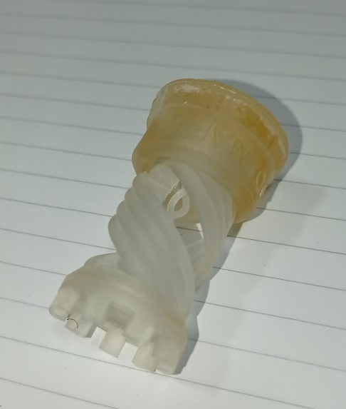
Rick, I just use STL for everything, don't even know where or why you'd use other formats. For FDM I slice with Cura. For SLA, Chitubox and, latterly, Lychee. All three are free and I haven't seen a case to pay for something else. I've printed translucent objects in FDM but I think transparency requires post-printing polishing to eradicate the layer ridges. For a big model ship that could be a fair bit of work. I've done one test print cycle with transparent resin and wouldn't call the results transparent. I understand you can improve this with polishing or (and I mean to test this) by dipping the part in resin post printing and re-curing. However, the common complaint is that the part takes on a yellow tinge during or after curing. In fact, if you look at this rook test piece that has sat on my windowsill for 3 or 4 months, the bottom, which has the greatest density, has become quite ugly. What you're describing sounds like a perspex/acetate level of transparency which I don't think is possible right now. Haze, for sure FDM is cleaner and it's easy to change reels and nozzles, but by the time you've done that and levelled the bed, my little Mars will have already printed my 2mm or 3mm high object and be ready for the next one :-). The mess of resin is a factor, though much less so if you get a wash'n'cure. Actually, I'm starting to sound like an evangelist for resin when in fact I think it's horses for courses and I've probably got more return on investment out of the FDM than resin printers, in so far that I've made lots of useful / replacement house and garden parts from filament but none whatsoever from resin. I did make a nice chess set though!
-
Sure is. Don't get me wrong, I'm hanging on to my FDM but I love my Saturn a lot more and that's the one I'd take with me into the lifeboat if I had to choose. I've had decent results with 0.2mm but 0.1mm was best described as hope over experience. Vermicelli galore!
-
As I say, no first hand experience of sintering at all, but here's an excerpt from one of my go-to sites, All3DP.com; "... engineering-grade parts with excellent mechanical properties, fine resolution, and incredibly fast, SLS (selective laser sintering) 3D printing is what engineers and industrial designers turn to for functional rapid prototypes and end-use parts..... advancements in technology have made SLS printers more affordable and compact... there are now a good number of office-friendly benchtop SLS 3D printers on the market.... SLS also offers a high degree of predictability in material and mechanical properties, so it’s popular in aerospace, medical, and regulated industries. There’s also no need for supports in SLS printing, which expands your ability to design and produce very complex geometries.... This technology can create parts that are finely detailed, strong, durable, heat resistant, and flexible (when needed) all at once. Printer manufacturers often boast that SLS prints rival injection molding products in terms of strength and precision. When compared to injection molding, 3D printing can create parts that have internal channels, lattice structures, and other features not possible with molding...." Resolution down to 0.05mm. Sounds good, doesn't it 😃. And we're talking metal, plastic, all sorts of material choices. Now the bad part - that resolution would currently set you back at least $40,000. If you can settle for 0.1mm, £6,000. If a machine was available that did even 0.1mm for less than $1000 I for one would be sorely tempted, if it was less than $500 I'd be first in the queue. I haven't tried Shapeways or any other print service but I probably ought to at some point, just to see what sintering delivers.
-
I've printed with a 0.2mm nozzle to the point where the surface finish is really not that bad, though sanding filament is much less easy than resin; it's more that getting FDM dialled in can be a right pain whereas this is super-simple with resin. I think all the manufacturers know what the community wants and this will determine the direction of development: affordable, reliable, easy to operate, no fuss, plug and play, no mess, no post print cleaning etc. Oh, and big. We want parts, not a process! Neither FDM nor SLA entirely fit that bill which is why I think, sooner or later, someone will try budget level sintering or whatever else comes closest to that spec (I have no experience of sintering but it looks like the real thing). The same is true with the software side. My ideal would be Tinkercad with bells and whistles. It took me 15 minutes to learn enough to produce my first part in Tinkercad, more like 15 hours in F360. Obviously Tinkercad is quite limited but with a few additions it could remain very useful indeed, not least because WYSIWYG.
-
Rick, I'd be a little careful there. FDM certainly has it's place and is currently a good approach for quite large or functional models but my guess is that it will be overtaken by resin within another few years, a bit like Blackberry vs Smartphone. Elegoo will be releasing the Jupiter early next year, with a build volume of 277 x 156 x 300 mm. This is creeping closer and closer to a 'standard' FDM build volume and, while the cost is at present relatively high, it will only ever come down. But in any case, I doubt the majority of hobbyists have room for giant models and the challenge we face is reproducing detail at a very small scale. The main problem with resin - fragility - is less of an issue once the parts have a bit of substance and, conversely (in my view), resin is much, much better for thin or very small model parts than FDM, so long as brittleness isn't an issue. And I expect resin manufacturers are beavering away at improving this aspect of resin for consumer level products. Personally, I wouldn't orientate the software to any particular production method unless that was either the point, or I had no choice. For all we know hobby level sintering or suchlike may be just around the corner.
-
See, I knew someone would see something I'm blind to now! Thanks, I think I'll try that, it should also solve the dowel hole issue and save me redesigning that aspect. There's some important detail on the outer face but there are ways around that.
-
I didn't explain this very well and should have used photos; The 'pins' side is the underside of the print and it has LOADS of supports. This face doesn't show on the model so finish doesn't matter much. This one is partially cleaned up and of course in practice this is relatively easy but unscientific. I don't think there's any way around this, this face has to be the underside as I need the A grade finish on the topside. The side piece has to be printed with supports on the face shown for the same reason. However, as the dowel sockets are on the side, their faces are perfect and, in engineering terms, this face comes out as designed, except that the dowel holes lose integrity as the tops are unsupportable. A ledge system (which I'll try this evening) will yield a perfect mating surface on the main body (but a rough top edge, which doesn't matter). But the mating face on the side piece will be an underside so imperfect. I can think of a few convoluted ways of getting two perfect mating surfaces which I doubt I'll even play with, they are that daft, but maybe someone here will point out something obvious or clever - it's easy to miss the obvious when you have your head buried in these things.
-
Yes, I've been thinking along those lines myself. I should have made clear, I can of course sand down the bumpy resin face very easily and the problem itself is not that problematic - the quest is for the best solution in the context of resin printing. Ledges, which probably is a better approach than pins for all sorts of reasons, still doesn't address that one mating face will be as smooth as the proverbial while the other mating face will still be a spotty teenager. Though easier to smooth accurately than the dowel method. The grail is to somehow get two perfect mating faces.
-
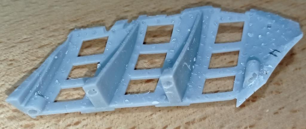
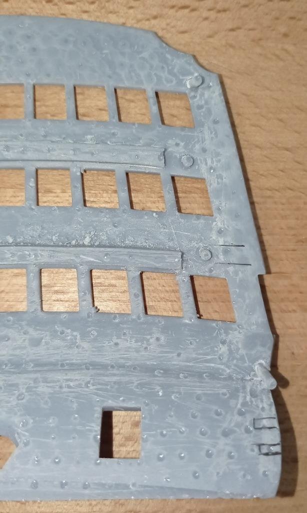
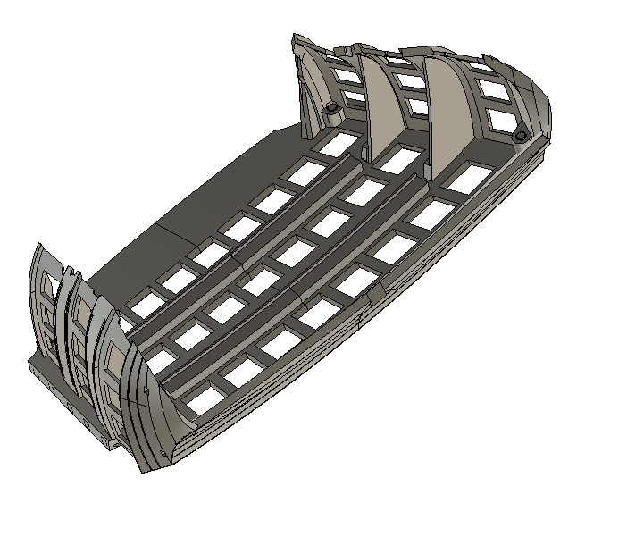
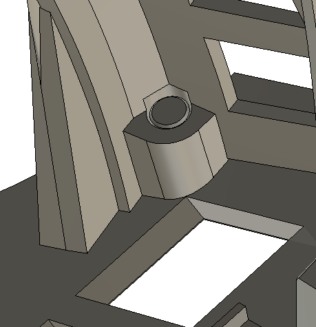
Can I pick the brains of this community. I need to join two resin printed parts as a T-joint. The main body is printed such that the jointing face is supported, meaning I lose some precision. The edge of the part to be 'T'ed is the side of the print so nice and sharp. I have very little tolerance to play with, 0.2mm max, otherwise it adversely affects the fitting of various dependant parts. As per the screen grabs, currently I'm using a dowel approach but this is unsatisfactory as the dowel holes get distorted during printing and re-boring tends to shift the centre by maybe 0.1 - 0.2mm. I'm scratching my head for a better approach and just thought I'd see if anyone has suggestions. This is the assembly, the two sides get joined to the main plate. The 'webs' are actually floors and are part of the sides. A close-up of the dowel method. The 2mm dowel is part of the main plate, the socket part of the side.
-
Dowel/kebab sticks will be my fallback for the spars if resin doesn’t work, but I’m fairly sure the masts themselves will go well in resin as there’s more meat on them and lots of room for a stiffener.
-
I found a solution earlier this week and will explain it with some pictures presently. The shrinkage itself isn’t a problem, in the sense that it doesn’t matter that the overall assembly will be about 0.5mm smaller than I intended; my design dimensions were in any case as much my choice as determined by the original kit and, so long as the whole assembly fits nicely together and to the hull, all will be well. There are about 30 ‘big’ parts to the assembly (and loads of smaller bits) and the shrinkage was preventing these from fitting together properly. I completely agree with what you say about the toolmakers, Daniel, that was part of my job in days gone by (not in modelling though) and I would have been very, very proud of the results if I’d made this kit. Especially the feathered edges of the side galleries and the rebates for the wales and rails, that is exceptionally fine work. I’ve settled for ‘close enough’ on my version and know it’ll need a little bit of putty here and there. Bill, the problem with resin printing small tubes is that you create a ‘suction cup’ in the centre during printing. Air gets trapped between the cured part and liquid resin which plays havoc with the centre hole. And when the tubes are this small, I’ve found that the hole gradually gets closed in anyway. If I had a lathe I could of course just bore them out post printing. But I don’t and, if I did, it would be miles easier just to turn them as solids from wood or steel! So, I tried making the centre of the main lower yard in 14 (!) sections that dowelled together. Nothing magical or scientific about the number 14, I just wanted to see how it went if I made lots of short, stacking tubes that I could bore out back to size by hand. I especially wanted to see if the inherent brittleness of resin meant the yard would crack on bending, bearing in mind the CF core. It didn’t, I could bend it way, way more than I expected without any damage. But it would need a fair bit of filling and smoothing of the joints - not that this would be a problem. Although I’m far from drawing any firm conclusions I think it’s quite possible to go down this route. My next experiment will be to try two halves, exactly like the kit, and see how that comes out. Seams around the ‘barrel’ are much easier to hide than those that run along the length, but I’ll try it anyway. In fact ‘round the barrel’ enhances it in my view, makes it look more handmade than machine part. Then see if either method works well all the way through to the very thin spars, where there is only enough room for a 1mm CF stiffener. The great challenge is that, once again, you’re dealing with super-thin wall thicknesses and the fragility of resin becomes an issue. It would be such a heartsink to be halfway through rigging only to have a spar literally snap off on you and you can bet it would be right in the middle of a complicated web of ropes!
-
Bill, did you shape the dowels or did they drop straight in?
-
Impeccable, Daniel. I have yet to tackle the entry port but doubt I will have the patience to do it at this level of detail. What software are you using for the scrollwork?
-
It is indeed, you can scale separately on the x, y and z planes, which is where the fun begins. As just about everything is curved, when you stretch one plane the relevant radii change. As before, not by much, just enough to be a royal pain. I did some experiments with design changes yesterday to (literally) give more wiggle room, that gave promising results and I’m sure I’ll find a workaround. Two steps forward, one step back.
-
Oh the frustration! I thought the very slight tweaks I had to make were just a need for a fraction more clearance here and there, that I was being a little too ambitious in my quest for a perfect fit. I’ve learned that it’s actually because resin shrinks during curing; not by much, average about 0.5%, which in 99.9% of instances wouldn’t make the slightest difference. But over a 130mm span that’s about 0.6mm, whereas my design tolerance is 0.15mm. So, I’m now chasing my tail with re-scaling parts, only the shrinkage isn’t even and the amount varies according to the mass of the part in question. I must have done something truly terrible in this or an earlier life to deserve this torture🥵.
-
Agree, reasonable price and it looks like a lot of content for the cost. Are you doing the ‘Rhino 3D Tutorials, from beginner level to advanced level’ module? It took me quite a while to find the right ‘tutor’ for F360 (Kevin Kennedy), traversing everything from superhero show-offs to one who seemed to know less than even me! I installed Rhino yesterday, will hopefully find time to start learning within the next couple of weeks.
-
I think Daniel would be more than able to do that himself if he wanted to, and probably make it look a lot easier than any attempt made by me. Bill, this probably isn't hugely helpful but, if you had a mind to do so, you could probably carve replacement parts from evergreen. Whatever you do they'll be an absolute pain to paint.
-
Thanks Pete. Still fiddling with printing, not too much more to do now.
-
That’s another good idea, won’t work in this situation though as these are parts that lie flat on others, just helps to have position pins. To answer the original question, they work okay, just need to run the sockets all the way through as some become suction cups and become filled in. I’ll cover it in more detail presently on my Victory log.
-
I'll be able to tell you later this evening, once the print run has finished. Your system sounds interesting, can you share a sketch or photo? I'm not sure I'd be able to work in clamping pressure, a lot of these parts are not even 1mm thick and are extremely fragile until glued together.
-
It's there on mine Bill, on sprue 8, the number is on the back side. Very small part. What is it with Heller, did they see no virtue in locating pins!
-
Yes, that's more or less me as well. It's particularly useful right now, when I'm also needing to experiment a lot with the printing. For instance I've found that 0.5mm locating pins (out of necessity, space is very limited) are perfectly printable but they break off too easily when removing supports. So I've just gone back through every item in the assembly, swapping to rectangular pins, which give them a lot more meat. Although this is fairly straightforward, down the line I'd know I need to design around that from the outset, but right now I appreciate how easy this it is in F360 to make a change like this. It may be that I continue using F360 in parallel to SW or Rhino, just as a tool that's good in some situations but not all.

