Kevin-the-lubber
-
Posts
1,232 -
Joined
-
Last visited
Content Type
Profiles
Forums
Gallery
Events
Everything posted by Kevin-the-lubber
-
 The more I see of this the more amazed I am by the level of detail, it's incredible at that scale, and so crisp. Are you sure you're not kidding us and this isn't actually 1:100 🙂. Up to now I have mentally refused point blank to look at anything smaller than 1:100 as even that's a challenge, but you're making me think again. Not to understate either than you're showing a great deal of skill in putting this together, I imagine at this scale it's difficult to get every part placed 'just so', but you're managing that rather well.
 -
Hi Greg, I'm happy to try to help with F360, while I haven't yet made a hull I've been doing similar shapes. Just explain where you're stuck. In case you don't know, Richard Dunn is doing a tutorial on hull creation over Christmas https://modelshipworld.com/topic/30596-free-hull-form-creation-training-workshop/#comment-870333 which you might find useful. He's from your neck of the woods too.
-
I tried glue stick once and once was enough. Messy old business. Hairspray is the my weapon of choice, you can rinse the platter under hot water and it’s good as new. I read recently that resin is less toxic than most household cleaners. But with a wash and cure machine the process is not actually messy at all, nor even smelly. I run my resin printers in my home office as they need a warm room, often have them quietly purring away during the day and you barely hear them. Still, I wouldn’t want to have the cats around them, much too risky.
- 460 replies
-
- 4
-

-
- Finished
- Flower-class
- (and 1 more)
-
There's nothing wrong with the kit hull, it's pretty good out of the box, depending on how you see these things. The primary purpose of remaking it is that, if it works out, I can make my stern 'kit' fit the heller hull almost perfectly. Having gone this far I'm thinking, why not. Just not right now!
-
That's a kind compliment but it's not quite fit for that yet, you wouldn't want to have to bash the bash, leastways I certainly wouldn't. The kit needs a few tweaks but, after working on this and nothing else for maybe 6 months, I need to take a break from it for a little while.
-
Tell them they can come now. I have my pyjamas and slippers ready. It's all preparation now, a lot of setting up drawings and what-not, so it'll probably go quiet on here for a few months as this can be a bit boring, something to do bit by bit, and there's nothing to show until the end.
-
I think we're on the same page there, Ian. I can't see myself doing micro detail below decks nor going too far down that track on the outside - only that which is readily visible to the naked eye. I'm glad too that I haven't just barrelled ahead on the Victory, I'm learning constantly and the slow journey is giving me time to learn things the rest of you have known for years. By the way, for all I've said about the Victory instructions being poor, you should see those for the Bluenose, they make the former look worthy of a nobel prize. Maybe I will do the Cutty Sark now, especially if it's good out of the box. I feel a need to have a ship on my office windowsill sooner rather than later 🙂. Meanwhile, a couple of pics of todays 'R&D' between weekend jobs. Staggered lap joints to simulate joining hull sections; glued together with CA and a little light sanding to blend the joints. Once painted the lines would be quite faint and of course wood graining is optional (probably skip that, not least because it would be unbelievably tedious to do in the software). If the section joints were strategically placed to make use of gunport edges and more randomly staggered, I think you would need to know they were there to spot them.
.JPG.6bde5c9bfa0941cb9684d33d3d1f25b0.JPG)
.JPG.974c8173d1ba5751a0e62b0a08f06d36.JPG)
-
You guys tempt me too much, this needs to stop 🙄. Ian, you in particular have a lot to answer for, all that encouragement to do a hull. (A couple of experiments with hidden lap joints today look good). I honestly thought, when I bought the Vic, that a kit in a box that big and at that price was going to come with the mother of all instruction booklets. Bear in mind I hadn't really touched a model kit in 40 years and my idea of an expensive kit was probably around the $30 level. Even now I still haven't got over the shock of the "by the way, we found these in a drawer, they might help a little... well, maybe not" moment when I saw what I got. The great, great danger is that, if I start the Cutty Sark now I might join the ranks of those that start but never finish the Victory. Mark, I think the Vic also has some thickness variation, I'll have to make some simple calipers to check this.
-
Hi Alan, I actually meant how flat is the basic plate i.e. the one you clip the glass or magnetic pad to. When I put a rule across mine it's just ever so slightly off flat, and I figured the same would therefore be true when I used the magnetic mat, hence went to glass (which I think was just better anyway). This is what I did wrt a spool holder; I had a spare bit of oak kitchen top (very nice!) and the spool roller assembly is screwed to this. The printer is just sat there. A big, printed threaded bar goes through the spool, it has a small bearing inserted at each end. The small piece you see at bottom right has a round bar that slides into the bearing and a hex shaped body that drops into the stand 'sockets' on either side. It's hex shaped so only the bearings roll. Then two threaded wheels with conical webs to centre and grip the spool. The threads came out fairly rough, I think this was probably more tinkercad than the printer or slicer, they are more a series of linked flats than a smooth helix. A brake. With bearings, the spool runs very freely and tended to over-run. I just apply a little friction to the side of the spool and, because the brake is pointed downwards, it also stops recoil. I did all the above in tinkercad, before graduating to Fusion 360, in fact I think this might have been one of my first projects so the design quality is a bit suspect! Works though. I remember I had to abandon using printed threads apart from the very big one and use 2 x M6 bolts for the brake. If you haven't already seen this, take a look at https://all3dp.com/. It has lots of helpful stuff about calibration, troubleshooting etc. I'd love to see you crack this inconsistency issue. Personally, I wouldn't mind spending another £100 or so on better parts if it meant being able to reliably print in FDM as it opens up the world of much, much bigger models like yours, but I did get pretty fed up with chasing my tail. Just in passing, I've used all sizes of nozzles and was regularly having success, on very small parts, with as small as 0.2mm. If memory serves 0.1mm was just pushing it too far. But the finish is never a patch on resin, if you want to see the difference take a look at my victory log.
.thumb.JPG.0be76ffdc1d10e0be3ec629f87f4cef1.JPG)
.JPG.a457986b3018ca7cc6660bef503c208b.JPG)
.thumb.JPG.a6472be5983c018cd8bf9f025a65117e.JPG)
.JPG.32f19ea459aec36f251c3b8d37c7feee.JPG)
- 460 replies
-
- 6
-
-
- Finished
- Flower-class
- (and 1 more)
-
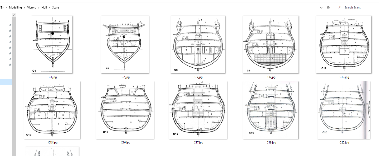
That’s a very nice bit of modelling Bill. I’m itching to start the Cutty Sark but feel this is of the same order as Victory, a big project, one that may take a long time to complete and I’d like to get to more or less your stage on Victory before starting it. So I’m going to do a couple of things over the immediate future. I bought a small and seemingly simple plank on frame kit, the Bluenose 2, off eBay this week, it looks like someone opened the box, fiddled a bit and then put it away without actually starting it proper. I’ve never modelled in wood and always fancied giving that a try. It was fairly cheap - have to say, I’d have felt a bit cheated if I’d bought this at full price, there’s not a lot to it - and I’ll do it just for fun and learning as, down the line, I’d like to try doing something like HMS Terror to a decent standard. Along the way, I’ve started playing with re-making the Victory hull in 3D. I’ve learned a lot through doing the stern and just want to see what’s possible, whether it’s worth the trouble, can I make it true to the rest of the kit or does it mean I’d inevitably have to remake everything that fits to the hull. I’m not concerned about having to remake the decks, these are easy, but I’d rather not have to remake all the stuff at the bow end! On the other hand, a custom hull would enable an absolutely perfect fit for my stern assembly, a perfectly fitted side entry and steps, thickened gunports and for these to be in the right positions, etc etc etc. The tricky bit will probably be finding a way to blend in the vertical seams as each half will need to be printed in about 6 sections. The horizontal joins are easy, the wales will take care of that.
-
Bit of a note to self; I had an absolute "doh!", slaps forehead, moment today. From the outset a struggle with the quarter galleries was to figure out their profile where they meet the hull. In the end, I really just used trial and error and it's still not as good as it could be. So why on earth did I not see the obvious: it is very, very straightforward to map the hull profile from the decks: you have the precise width (deck width + hull thickness) at whatever stations you choose to use, readily measurable waterline heights via distances between decks, and an absolute reference in terms of where the hull meets the stern plate. Heller even very kindly provide ready made centrelines on three of the decks! I'll be testing this out presently and bet it is accurate to within a very small degree of error. This principle should hold true for anything where you want to model something new to fit the hull, i.e. the side entrances.
-
Looks great Bill, you've got so much done in such a short timeframe.
-
Hi Alan, all that frustration with printing mirrors my experience and saw me shift to resin, which is much easier, though still has its challenges. However, there are a few things I haven’t seen you mention, which you may or may not have looked at, which I’ll go through just in case and perhaps for the benefit of others. 1) calibrating the filament feed. I suspect you’ve done this, used pronterface etc. if not, shout out. 2) is the basic bed flat. I know mine isn’t. It’s close but does fade off very, very slightly towards the edges. I use a glass platter held in place with small document clips so this in turn doesn’t distort, and hairspray (actually, I bought the pricey 3D printing stuff) and this solved most problems with lack of adhesion. 3) replace the Bowden tube. This made the most difference. I think the stock one is a bit rubbish. The ‘go-to’ brand is Capricorn, not very expensive. The friction from the tube results in less filament going through the nozzle and the undue resistance can cause the gear wheels to grind the filament. This might be why your wheels got wrecked. When I swapped to Capricorn, if the model stuck to the plate, it would always deliver a decent print. 4) filament. I now only use PETG. this is much more forgiving that PLA, and less rigid as well. I have no idea which brands are good, which aren’t, think this remains a lottery variable. Yves, if you’re reading, can you tell us what brand and type you’ve used? 5) drying the filament - see you’ve done that, I stick mine in the oven on a VERY low heat for a few hours. Wife not too happy but needs must. Even after a few days it’s not as good as new and my guess is that this is moisture related. 6) get the filament spool off the machine and control how it rolls. Basically, make a spool roller with a brake. I’ll send you stl’s if you want, for a Heath Robinson affair I knocked up way back, that has the spool mounted on a board besides the printer; as you’ve probably noticed, it can be ‘jerky’ when mounted on the chassis and this cannot possibly be a good thing. Just reply here or via pm if you want stl’s or a photo 7) ditch the paper, use feeler gauges. I was then at least able to determine what gap worked and what didn’t, brought some science to levelling, and understand by how much there was variation across the levelled plate. If in doubt, replace the nozzle. They’re cheap as chips, I treat them as short life disposables and you at least get a guaranteed clean measuring surface with a new nozzle. 😎 wisps: use a heat gun. Just wave it over the finished object and the fairy hair shrivels away to nothing. Practice first though, it doesn’t need much heat. I now need to incorporate all your learning to see if all of this taken together results in reliable printing. For me it’s always been hit or miss, I can do multiple prints of even fairly big objects without any issue, change to a different object and inexplicably get spaghetti. Drives me up the wall! I have never managed to get a single bit of ABS filament to stick, major disappointment as that would be my first choice of material, not least because you can smooth it with acetone I.e. minimal filling and sanding. Intrigued by the rabbit ears, will try that - always have to use a raft. BTW, I generally print at a speed of 50 but run the hot end and bed at much higher temps than you, 235 and 70 respectively and use a superfine or ultra fine cura profile. Less than that and I routinely got lack of adhesion to the bed or between layers. I think that, as has been suggested, the out-of-the-box ender 3 is a decent starter kit but you probably do need to upgrade most moving parts to get what we’re all looking for. And, I am most definitely not an expert, I’ve been neither more nor less successful than you but the above are things that worked for me, and hopefully some may be useful for you too. Last but not least, the model itself, so far, looks great and I’m sure it’s worth all the pain.
- 460 replies
-
- 3
-
-
- Finished
- Flower-class
- (and 1 more)
-
I couldn't help laugh at this business with the balls. I imagine a fortune was spent on what was probably fairly state of the art tech for the time, but still a pair of balls to communicate critical information. Is this system still in use? Brilliantly simple of course, as were a lot of 'old' ideas.
- 454 replies
-
- 3
-
-
- Union Steamship Company
- Stepcraft 840
- (and 3 more)
-
That's good that they're in the box. Once you're 'officially' allowed to see them it would be good to hear what you think of them compared to what we all got with the Victory, aside from the rigging. Despite my rantings, because I am at a far, far earlier stage than you (and heading backwards I think) I might overcome my objections and buy them anyway.
-
I forgot to follow this thread! I'll be attending too. I haven't got very far with learning Rhino yet, probably just need to spend more focussed time than 30 minutes here and there, but I'm very keen to see how to get smooth curves etc, especially on the cutty sark.
-
She’ll know, you know, they always do. My dear old mum used to make us stand in a line and stick our tongues out to see if we were lying. She’d say she could see a black spot if we were. How she convinced 6 kids to believe that for about 10 years, lord knows. Even by the age of 3, when I tried the same, mine would look at me as though I was some kind of half-wit. Did the SR instructions look good?
-
Yes, I saw that too Bill. I hope they have the good grace to at least put a crookedly stapled version in with the kit from here onwards. While it doesn’t really matter that much when you find sites like this, this is the haunt of those who are all about making the most of every kit, and I can’t help picturing someone like me at 12 or 13 years old getting this wonderful kit for Christmas but being defeated by the abysmal instructions. For all that these big kits take most people years to complete, I think you could probably throw it together out of the box in two or three weeks of school holidays and enjoy every moment, with decent instructions. You shouldn’t have to pay extra for them! (I think I may be ranting, I shall stop). On a side note, has anyone ever seen or heard of a Victory build out of the box, no bashing, plastic sails etc? I remember Pete Coleman was always hoping someone would just do that for a change, as a guide for others. It’s incredibly tempting at times to do just that with one of my kits, no painting, just cut and glue, cut and glue. That’s what I did with my Endeavour one Christmas 50 years ago and it really didn’t look that bad, sat on the windowsill for years.
-
It looks pretty darn tidy to me, especially at that scale. Model photography is a cruel mistress.
-
An extra £40 for the assembly instructions? It would need to be pretty damn good at that price.
-
Same here. If you ever have to send a fax your local hospital is the place to go. Baffling, in this day and age. Bill, I've also loitered on their site once or twice, just assumed that, as they don't seem to have a 'shop', this is just a catalogue of what you can buy from a Heller dealer. It'll be interesting to hear how you get on. Is it just me or does everyone seem to be slowing down on their kits with Christmas approaching?
-
Maybe, like us, for them it's a hobby? 😁
-
I can't point you to the exact place but I know I've come across something, in my travels, about getting replacement parts and I think I remember the poster saying they never respond to emails, but do respond to fax and are very obliging if you ask nicely. I have no idea how you'd fax these days.
-
Thank you Mark. Sadly, I haven't been able to detach myself quite enough and here's a clue as to where I'm headed. I keep thinking of that scene from the Clint Eastwood movie 'The Unforgiven' (I think) where the Clint tells the gunslinger in the bar to walk away. He does, then comes back in 2 minutes later and says ' I had to come back, didn't I' or something like that, and Clint says' I know' (and then of course sends him to meet his maker).

-
Not feeling easier over here. Just more visible. Maybe it's easier to hide the sins at 1:700? 😝 Yes, I too was mixing it in the cup with the wrong end of a paintbrush. To be honest it worked fine but, as we we used to say in the trade, that's all very well in practice but no good in theory.
.JPG.7ba1746f88085c0c0e0e2dee2d1b34ec.JPG)
.JPG.166ec42f0431eb3318f99a5317bc6f34.JPG)