
Kevin-the-lubber
-
Posts
1,233 -
Joined
-
Last visited
Content Type
Profiles
Forums
Gallery
Events
Everything posted by Kevin-the-lubber
-
 Not feeling easier over here. Just more visible. Maybe it's easier to hide the sins at 1:700? 😝 Yes, I too was mixing it in the cup with the wrong end of a paintbrush. To be honest it worked fine but, as we we used to say in the trade, that's all very well in practice but no good in theory.
 -
I've been casting around for a 'take a break from the victory' kit for a little while now and have to say, the small number of parts and angularity of a more modern ship is appealing. But 1:700? No way, not with these hands or eyes! You're a brave man OC, and making this look much larger than that scale. I read all the earlier stuff about taking the step into air-brushing; me too, earlier this year. I bought a cheap kit off amazon, chinese of course and perfectly fit for purpose, and am just starting to get the hang of the basics. I really like that, unlike rattle cans, you can lay down very fine layers which dry within minutes. I've only used vallejo model air paints and had a problem with yellow ochre, which kept clogging the tip in no time at all. Adding some vallejo flow improver fixed that completely. One micro lesson learned so far has been to premix the paint and improver in a small bottle so I can just top up the airbrush cup as I go. I also learned just this weekend that I could leave the paint in the cup for much longer than expected without the tip drying out and clogging; I probably went maybe 30 - 45 minutes between coats. So far I've been pretty religious about cleaning between colours and at the end of a session. In fact I spend more time cleaning than painting! But I do need to learn how to use the brush to paint fine detail and lines as, so far, I'm just body-shop spraying. Oh, another thing - the airbrush is handy for blowing off dust and stuff and, in my game, for speeding up the evaporation of IPA after washing resin prints. I noticed this kit has some printed parts: it so lends itself to resin printing...
-
Thank you, Stoofvless; I gave up trying to use the kit parts after realising very quickly that I simply don’t have the hand-eye coordination to paint that finely. And then spent about 9 months compensating! I keep forgetting to mention, I do have the gunports lids made, just haven’t decided yet on open or closed. I have yet to make the lanterns, these look very simple and a fun thing for an evening or two, though I’ll need to use wire for the brackets.
-
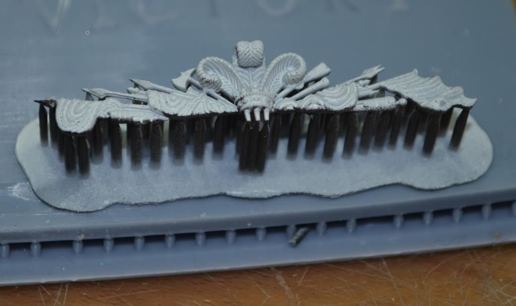
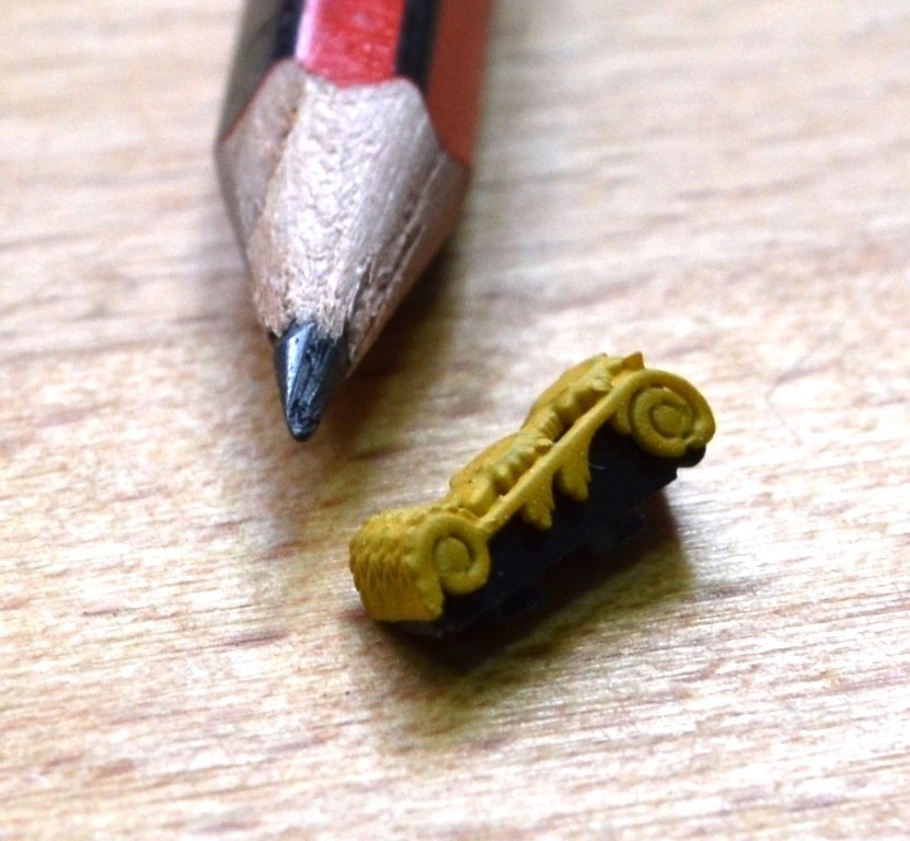
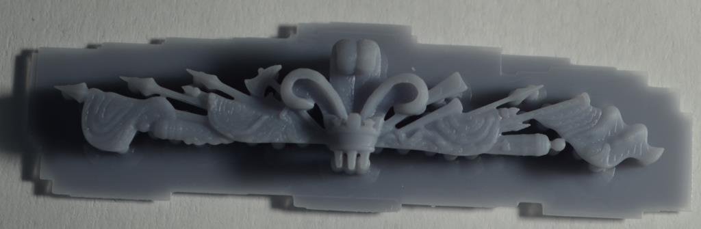
Thank you, gents. It's certainly been a learning experience. Odd though it may be, it's the corbels that give me most satisfaction. These are so very tiny and it took me many, many attempts to find a way of making them that didn't have them literally breaking apart as soon as I touched them. These would probably have been better done as decals (it's on the 'to learn' list). Funny how each stage presents it's own set of problems. I'm still learning how to glue better, so I have time to make adjustments, no overspill etc without having to sit there holding the pieces together for 20 minutes. I'm even more so learning how to paint, air-brushing in particular. I can do broad sweeps, body shop style, but not yet fine lines and all that. Which kind of brings me on to the glazing. I'm still experimenting with this. For a while I've had in mind to have a 'bottle-glass' effect, not so much for reasons of historical accuracy but because I think it would add texture and character to the stern. You kind of want the viewer to dwell on the stern, be drawn in and I think bottle glass will make the stern more interesting. I've found a nice 'beginners error' consequence of over-spraying translucent, printed resin with clear gloss enamel. If you lay down too much enamel in one go, it puddles and dries in a bottle glass shape. My ongoing experimentation is around how to 'shape' that puddling. It's probably as easy as dragging the puddle with a cocktail stick. Another idea that came to me this morning is to try heat - remember how acetate would deform and bubble if you put a lighter under it (or was that just me being me!). As you can see, below, I've got a more defined trophy of arms now, which I'll paint once the mood takes me. The strange finish you see here is grey primer on the top but black on the underside, because I know from an earlier attempt that this object is way too small in real life to be able to get the paints into every nook and cranny without smudging, so the black bottom will hopefully prevent any flecks of grey still showing and merge the trophy into the stern. At some point I'll probably also try Daniels idea, that it should just be a crown rather than fleur-de-lys, though I do like the FDL. In case anyone is struggling, as I did, with meshmixer, the fix was incredibly simple - I had to first make the object solid in meshmixer, that's all. After that, you can sculpt to your hearts content. Until I discovered this, all I ever seemed to achieve was a complete mess of polygons, vertexs and other things I neither understand nor care about 🙂 I want to try out Rhino 3D now, see if it's a better tool than F360. While I like F360 a lot, it has issues that can make it hugely frustrating and I certainly wouldn't want to use it for another project of this complexity unless there was nothing better (for me) out there. I'm also thinking I might change horses model-wise, for a while, take a look at my Cutty Sark, start thinking through what I want to do with that before even starting on it.
-
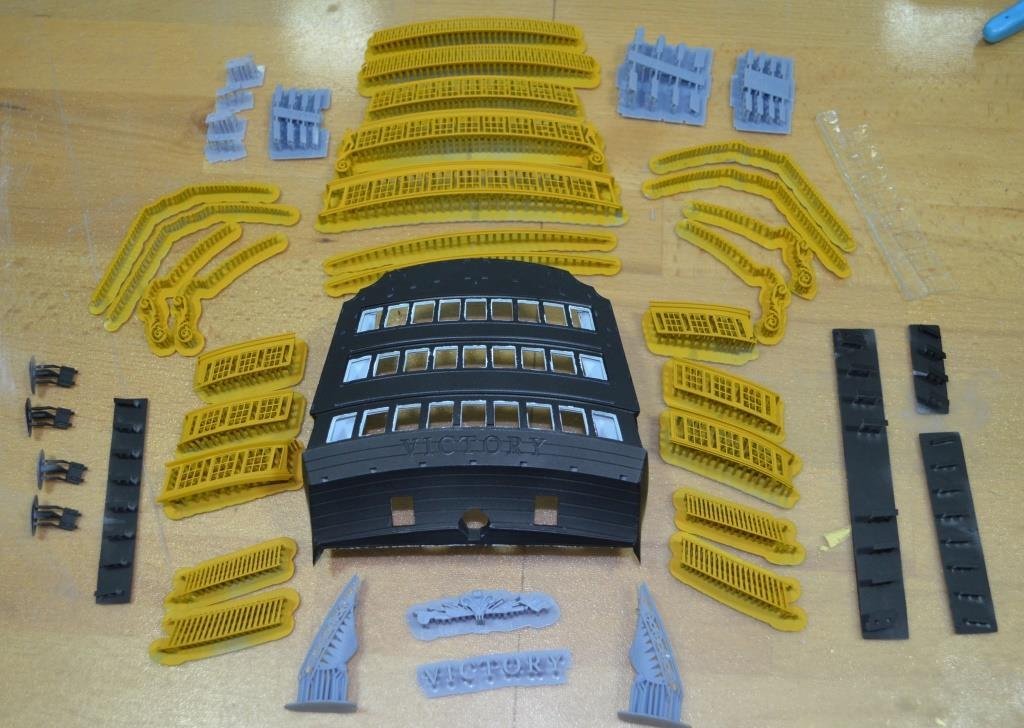
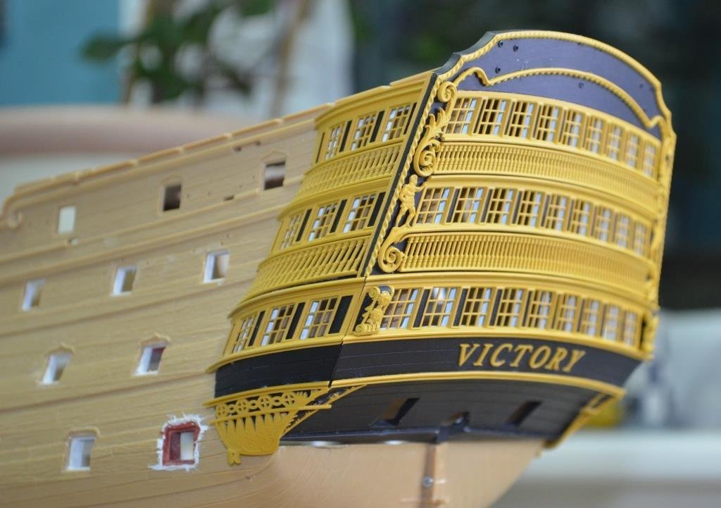
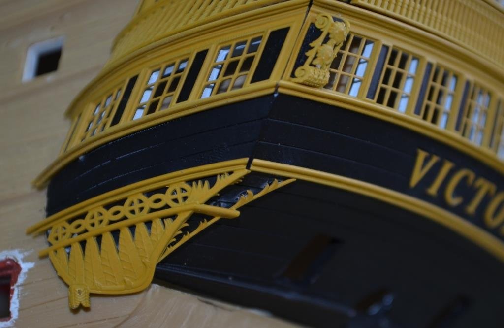
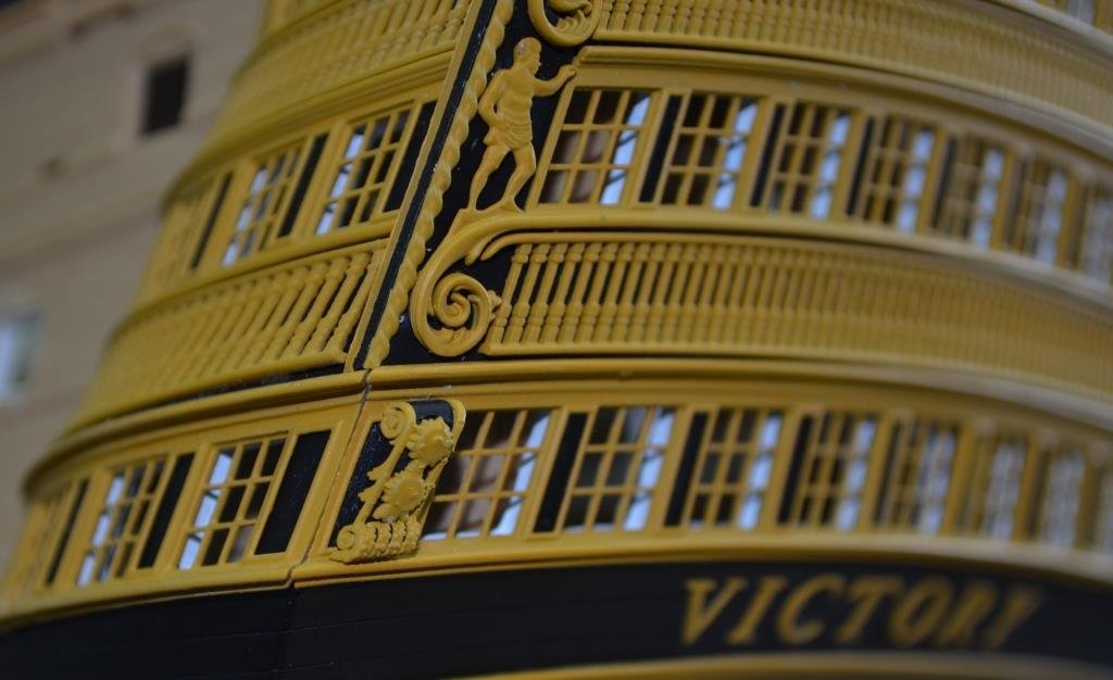
Dress Rehearsal: The 'kit' (more or less): Assembled: This is just glued up, I haven't touched up the joints yet and probably never will on this version. I have yet to paint the trophy of arms and do the glazing, I'll cover these in another post. I'm pleased with the outcome overall. There are some tweaks to be done (at a later date); the lower balustrade on the side gallery appears to protrude, it is more the case that the main stern plate needs to come out a fraction more. In real time the error is almost imperceptible. At the time I made the figurine integral to the middle window row I still hadn't learned how to sculpt 3D files, and is a poor effort. This will be re-made to match the depth of the scrollwork and to be more lifelike. I gave in to a lack of self-confidence when painting the stripes down the edge of the stern plate and just painted one stripe. I should have been braver or thought about it for longer and painted all three. I have a method in mind now, for next time. Most of all though, I'm just glad to have got it finished to a 'good enough' level. I was not enjoying this anymore a couple of months ago and would have gladly thrown in the towel if I wasn't such a stubborn chap. So, apart from painting the trophy and doing the glazing, I'm going to put this to bed now, have a bit of a break, try out some different software and mess about with much, much easier areas such as the side entrance and cannons.

-
... and this one's me, with what looks suspiciously like HMS Warrior in the background. Each time, as I walk towards Portsmouth dock after parking the car, I can see the masts and tops poking out above the buildings and get excited thinking 'they've put them back!'. And each time I forget that those are the Warrior's and that poor old Victory gets stripped ever more each year. At this rate I'll go there one day and just find a little plaque that says 'HMS Victory was once docked here'. All in a good cause I suppose.

-
I may still be misunderstanding (I'm good at that) but, in case it's helpful. you can easily get cross-sectional sketches using Fusion 360. https://knowledge.autodesk.com/support/fusion-360/troubleshooting/caas/sfdcarticles/sfdcarticles/How-to-create-a-sketch-of-a-cross-section-of-a-3D-Model-in-Fusion-360.html So, if you created the basic hull shape in F360 with just a few stations you should be able to slice this any number of times along the keel and get precise cross-sectional 2D sketches at each station. You'd need to add dimensions to each sketch manually (F360 will calculate the dimensions but you have to tell it which points to measure on each drawing) which might be a bit of a slog but not nearly as much as doing this on paper. And of course you can then fiddle with dimensions and detail at each station to create new profiles and loft again using these for a more accurate hull. I imagine you can do the same or similar in other CAD programmes. Egilman, I don't think you can really do this in TinkerCad, it's extremely limited in the splines department and Jaager, as Dr PR says, whatever you use, the learning curve is going to be long and steep so it's well worth browsing the market before you commit. As I've implicitly plugged F360 I should add that it's very good on the whole (and free) but can drive you up the wall when it's not, and lofting is one area where it can be, shall we say 'playful'. Not always, mind, sometimes it's a dream, but sometimes it's not.
-
😃 I wasn't for a moment suggesting they were purely for looking at (though I guess that was always a possibility) 😂. More asking how a 3D printed plane flew compared to traditionally-made models. Better, worse, no different? I guess this is filament printed so is pretty strong and, unless you have access to the mother of all filament printers, the fuselage and wings are built in sections?
-
Very interesting. Does it fly well? How hard and expensive is it to make?
-
I’m not sure if I’ve understood what you’re asking for but from the description think this is probably standard fare in any normal CAD package. You can certainly draw points and use them to create arcs and splines in Fusion 360, which has a free hobby licence, and I expect the same is true for FreeCad. There’s a thread running on this forum called “an attempt to create a hull…..” or similar, in which we’re talking about various CAD packages, and the methodology of hull drafting, that you might find helpful.
-
Looking good Bill, looking good. This is fascinating to watch - I see how long it takes you to do a stage, multiply by about 100 and there’s my timeline. So I need you to crack on and have it rigged by Christmas, otherwise I’m sunk.
-
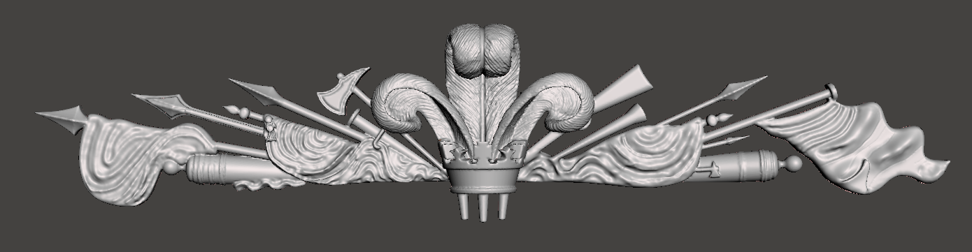
Messing around learning Meshmixer now. I made the basic object in F360, then sculpted the flags and feathers in Meshmixer. Looks nice, doesn't it. Pity the sculpting is all but invisible when printed! I guess this is pushing to the limits of DIY resin printing (you can see it's bridging many of the gaps) and I need to exaggerate the detail a bit, and/or try a bit of paint and ink to get the relief.
-
Something that may amuse you. About 40 years ago I went to work in a shipyard in Northern Germany, my first experience of shipbuilding. I was that green I literally had to ask which bit was the pointy end, having spent my apprenticeship in a factory that made heavy machines. In the shipyard, I was put on deck sections, with a seasoned german guy as a buddy. The deck sections were were basically 8’ x 4’ sheets of 20mm or 30mm plate (iirc) which I was welding together using submerged arc before MIG welding 12” stringers across the lot. At the end of the first long, cold day, my German buddy had me weld a lug in the middle of the section we’d spent the day building, which I did without giving it any thought. Now, I was a decent welder but nothing special, definitely not what was called ‘coded’, which meant the weld integrity would be of a very high standard. Imagine my utter horror when he immediately called the crane in to lift what must have been about 32’ x 32’ deck section by now, weighing lord knows how many tons, on the strength of that one lug. And trust me, these guys didn’t hang about. It was way up in the air and going across the yard long before I could sufficiently get over the shock to protest that I wasn’t sure my welding was up to much. It always looked nice, but I laid down my share of porridge. In fact I think they knew perfectly well how petrified I was and relished the moment, knowing full well that the welds would be fine, or they wouldn’t have done the lift. Not that their confidence had the slightest effect on my own - I did then what I still do now, horribly over-engineer everything, and would whack on an extra 2 or 3 lugs whenever I got the chance thereafter. Odd as it may seem, within another year I was working at the opposite end of the spectrum, still in Germany but on the new Airbus, making small, beautiful compound curved parts that were light as a feather. A bit like model making in a way. Happy memories in both cases.
- 454 replies
-
- 3
-

-
- Union Steamship Company
- Stepcraft 840
- (and 3 more)
-
That guys work is indeed extremely good, both in terms of the hot rolled plate look and welds. And I speak with some authority, having worked as a fabricator-welder on many heavy steel plate constructions including ships. However, you'd have to be pretty close up to the ship to see the roughness of the surface. Although I have absolutely no experience of modelling this, I agree with your thinking. If everything was perfectly smooth and contoured it would look more like a yacht with a super-structure than a huge steel ship.
- 454 replies
-
- 1
-
-
- Union Steamship Company
- Stepcraft 840
- (and 3 more)
-
Just as soon as I hit the 'final print' stage with this stern model, I'll start learning Rhino. I can save the print file and chitubox file in Chitubox, but not the STL. Lychee is great for mirroring supports and it's also easier to see their placement, but it's awful for mirroring parts and any major re-orientating on the build plate after adding supports i.e. to get the most objects done in one print. So, todays bright idea will be to build the supports in Lychee, then export the STL, mirror and reorganise in Chitubox. And even as I write that I have a doh! moment and realise I could do the same in Lychee; do the supports, export as STL, reimport and mirror/arrange.
-
Slicing from within the software would be a bonus for me, though not of much value as there’s nothing particularly ‘broken’ in that area. Slicing software, integrated or standalone, with a super-intelligent orientation and supports placement algorithm, now that’s worth having. I’ve been using Lychee a lot recently, over Chitubox, both have shortcomings. To be honest I don’t even know why or when it would be better to use anything other than STL, it seems to reproduce what I’ve modelled perfectly well. I get the odd non-manifold warning in Lychee but just ignore it as fixing the holes in mesh mixer sometimes destroys the entire part. There’s a flip side to competition you know. It can also drive corner-cutting and spin. F360 is a case in point, you’ll find no end of threads about very long-standing deficiencies that Autocad clearly have no intention of fixing because there’s nothing in it for them and they seem to only have one or two people on the community support side for the entire world. But they’ll still tell you it’s the bees knees of CAD. Of all the criteria you listed Rick, I think I’d like good error handling most of all. All of the other things are of course very important but the nature of this game is trial and error and you really don’t want the F360 experience where, if it even gave decent error messages, it would usually say this: “You’ve tried to do something I don’t know how to handle. I’m thinking on it. I don’t know how long this will take. Longer than you want, that’s for sure. I might give up in 5 minutes, I might never give up, either way, you can’t do anything more while I’m thinking, so go and find something else to do and check back periodically. By the way, I’m sorry if I destroy your file while I’m doing this. Stuff happens.” I wrote simple software, of sorts, myself many years ago and probably put more effort into the error handling routines than anything else.
-
That's what I'm after... probably wishful thinking.
-
Thanks, the table of offsets is well worth knowing about, makes sense now. I guess until I find time to try Rhino I won’t understand the benefits of surface over solid from a user perspective but hopefully I’ll get there soon enough.
-
This is interesting though some of it goes over my head right now. However I'm a firm believer that, if you understand why 'it' does something this or that way, the software in this instance, you're halfway to fixing the problem of why it sometimes doesn't do that. You're also halfway there to exploiting the full potential of the tool. So please carry on, chair pulled up. I read 'offsets' a fair bit in this and other threads; to me, an offset is one line or edge offset from another. So what are the points offset from, as described? CSG or curve sweeping (which I assume translates to solid modelling or surface modelling): in what way does it make a material difference? What and why does one do X whereas the other does Y? I know I can model a hull in F360, because I've already modelled the equivalent shapes. From googling, I understand it's CSG, as are all the other common CAD's I know of (Rhino, Solidworks, SolidEdge, Freecad and of course my old friend TinkerCad). It's a bit clunky, the more precise you want the shape, the more profiles through points (offsets?) you need to draw and loft through and the more you'll want to throw your computer out of the window. But it's do-able. If I'm only ever going to model 2 or 3 hulls in my lifetime (probably an over-estimate as I'm a slow worker), would I still be better off using surface modelling? I'm not even going to ask about cubic interpolation - I looked it up on wikiversity, that was enough to get me swiftly back to fettling bits of plastic!
-
Most tradesmen, let alone modellers, would give their right arm for a fit that good. You have good reason to be pleased!
- 454 replies
-
- 4
-
-
- Union Steamship Company
- Stepcraft 840
- (and 3 more)
-
It's on the to-do list. I didn't realise they polish them. I did wonder whether they are cast from a 3D mould as I couldn't see any layer lines. They are very clear but the diffraction (?) means they aren't exactly see-through, in fact in that respect the panes I made months back were better as they were dead flat and only frosted on one side.
-
Egilmans call, as the OP. Digression never bothers me too much as you often learn something interesting along the way.
-
I thought I should mention - at dinner this evening my daughter gave me a tour of her unbelievably expensive teeth braces that mean I have to work for another year 🥵. They are called Invisalign and are made from transparent resin, as the usp is that they are virtually invisible. Maybe worth looking at dental resins.
-
I know that feeling Richard. Despite years and years of fine limits trade experience I still fooled myself into thinking 0.1 was LOADS of room (it isn't), forgetting that the entire reason for tolerance is that even metal does it's own thing sometimes and decides to cut or bend a smidgeon bigger or smaller here and there. I'm amazed that you're getting 0.2 on plywood, at that scale and especially with wood I'd be happy to get to within 0.5. It looks fabulous by the way.
- 454 replies
-
- 4
-
-
- Union Steamship Company
- Stepcraft 840
- (and 3 more)
-
Ah, yes, talking at cross purposes. I didn't particularly mean plank and frame but in a sense it's the same thing - I meant part by part, just like a plastic or wood kit, rather than pre-formed whole sections. I came at it from the perspective of, I suspect, the typical modeller - we like glueing things together, while trying to make it look like no glueing was involved 😂. The fun is in the making rather than the finished object. I'm not so sure your intent is readily do-able in either SLA or FDM, not just because of the material transparency issues but also because both techs need overhangs to be supported during printing. Another very easy, no-cost way to test it out is to design a section and ask a commercial printing house like Shapeways to quote for the printing, they'll tell you whether it can be printed transparent and with what tech.