


Kevin-the-lubber
-
Posts
1,232 -
Joined
-
Last visited
Content Type
Profiles
Forums
Gallery
Events
Everything posted by Kevin-the-lubber
-
 And I guess you would you also be able to export them as STL's for 3D printing? At some point I hope to do a whole ship in 3D and think it would probably be immensely satisfying to do so to your level of detail.
 -
Fantastic modelling Waldemar, it looks very nicely faired. Once the 3D work is complete, what do you plan to do with that? Will you use it to make templates or drawings for making each part in wood?
-
That’s a nice idea. I’ve not yet committed to any particular mounting method for my Cutty Sark other than not the kit way, and you’ve given me food for thought.
- 3,560 replies
-
- 1
-

-
- clipper
- hull model
- (and 2 more)
-
Marc, Ian, thanks. This was surprisingly quick, easy and fun to make. And I’m pleased to have now got a couple of items properly finished! I look at the production rate of others on the forum and just don’t know how they do it.
- 444 replies
-
- 2
-
-
- Cutty Sark
- Revell
- (and 2 more)
-
Bill, lucky for me then that the Kearsage was the base model. I had a good look at it when it arrived and will look forward to working on that, probably late this year or early next year. It sounds like you are doing to the Alabama what I’m doing to the Cutty Sark. I’ll almost certainly do something similar to the Kearsage as I dislike the split deck and now have a reasonable method for making my own. The model is quite similar in approach to the CS - illogical divisions, positive grain and so on, but for all that, what looks like a very unusual, interesting ship to make. I also quite like that there aren’t dozens of build logs for it; it’ll be good to have to figure it out myself. On a different tack, my second CS arrived last week, what’s interesting is how much more flex there is in that newer pressing. Less flash as well. I don’t know what I’ll do with it though. Possibly just keep it for a rainy day. I’d like to have a go at the very beautiful Glory of the Seas but make that entirely myself, mostly via 3D printing. But that too is for another day.
- 444 replies
-
- 3
-
-
- Cutty Sark
- Revell
- (and 2 more)
-
It’s probably mild steel, but at the low grade end of things. As luck would have it I threw away miles of copper wire and old armoured cable that I replaced when I built my office a couple of years back, which would have come in handy now. I’ll have to think of a new project to generate some more 😀
- 444 replies
-
- 2
-
-
- Cutty Sark
- Revell
- (and 2 more)
-
It sunk in because I’ll be using that wire for the railings but, in its normal state, it’s very soft and ductile and I could foresee many happy hours trying to tease it into a ‘perfect’ shape. After twisting it’s surprising stiff and I guess with enough practice (and nothing better to do!) I imagine you can tailor that to your needs. Digging very deep into memories of my apprenticeship, it’s all about changing the crystalline structure. I can see me begging for unused Victory wire sooner or later!
- 444 replies
-
- 1
-
-
- Cutty Sark
- Revell
- (and 2 more)
-
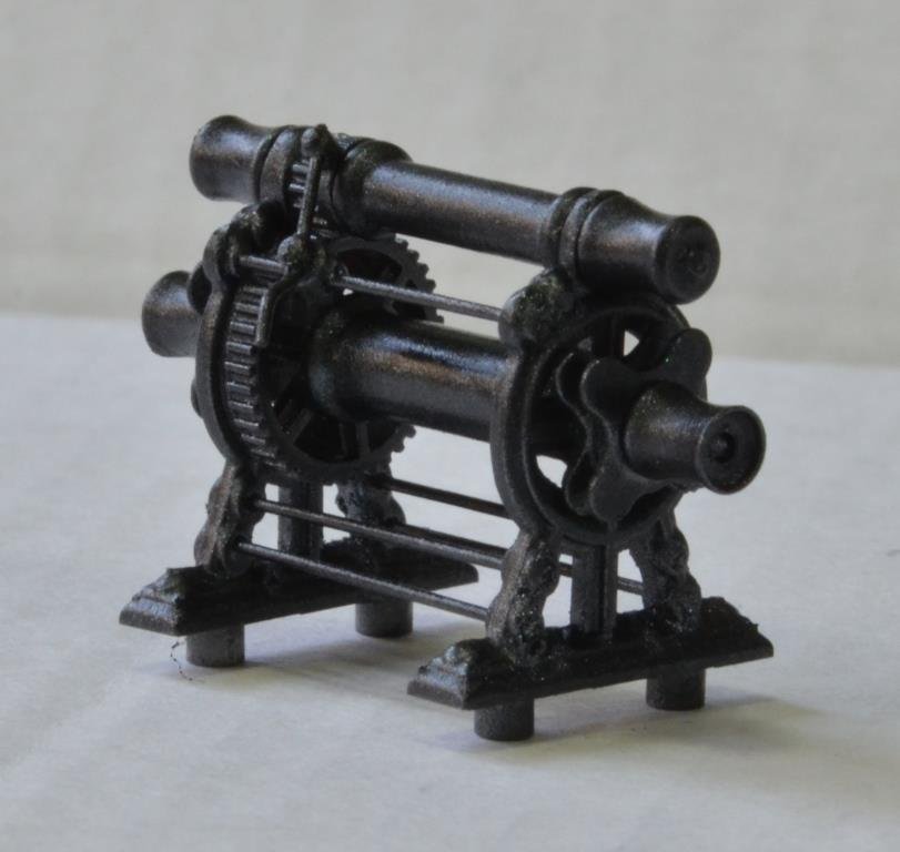
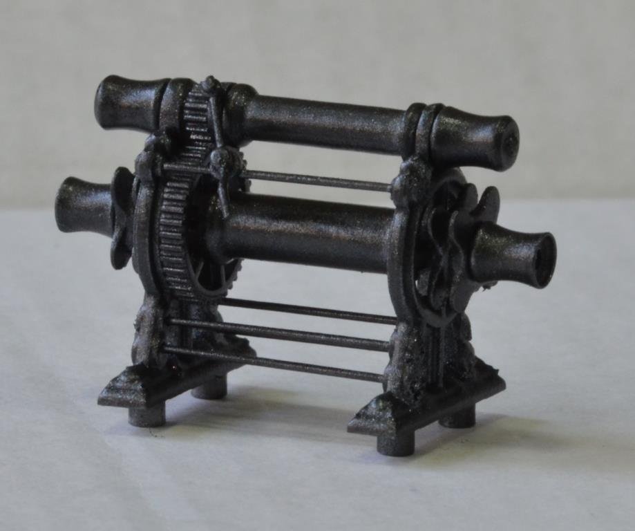
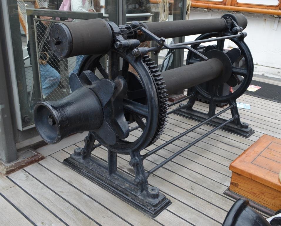
The last 3 or 4 weeks have been a little fraught for various reasons, including me breaking the motherboard on the larger resin printer, and I've been more re-grouping than forging ahead. Lots of cussing but the manufacturers very kindly sent me a replacement, gratis, and I'm back in business. However, bit by bit I'm producing each part to the level I want and will soon start another long painting session using lessons learned through trial and error. Meanwhile, I remade the winches as I really didn't like the kit parts. I do still need to take the shine off the rollers as these are supposed to be blackened wood. As ever, there are about 20 parts and even though it wasn't intentional, it did actually work as a machine before I locked it up with glue! I also learned two useful things along the way; - CA dries incredibly quickly on carbon fibre: the axles are 1mm CF and I had to do a dot of medium CA on the ends instead of shafts as it set almost instantly. Must be some kind of chemical reaction or that it soaks straight into the fibres. - twisting wire really does straighten and stiffen it hugely. I read that tip on here somewhere and, for the tie-rods and handle I once again used the 0.5mm gunport lid wire from the Victory kit, put a pin vice on each end and gave it many turns while holding it straight.
- 444 replies
-
- 6
-

-
-
- Cutty Sark
- Revell
- (and 2 more)
-
I guess it’s probably a bit of a grind at times, doing this day after day Bill. But it’s coming along nicely from where I’m sat.
-
3d printing process
Kevin-the-lubber replied to henrythestaffy's topic in 3D-Printing and Laser-Cutting.
Neither is mine but, to be honest, it was only the smell that bothered me. One day I might build a large, heated and ventilated enclosure for the whole lot but it's a low priority. But then again, mine is in a garage so the smell doesn't bother anyone else. Different if it's indoors. -
3d printing process
Kevin-the-lubber replied to henrythestaffy's topic in 3D-Printing and Laser-Cutting.
How odd that we have almost opposite experiences. I do get the occasional failure, invariably supports-related but I'm able to get away with the lightest of supports on small items, though not bigger things. And I have needed to redesign some things explicitly to be able to deal with support removal and the resulting surface defects. It sounds like I should give anycubic another try. -
Ian, when I eventually saw a nature doc about them I was surprised at how big they are - they really are, aren't they. These sound like wonderful experiences. Even though I have had many of my own I'm still envious. There ought to be a forum just for these stories. I'd never heard of the duck tolling retriever breed - lovely looking dogs and I laughed out loud at one part of the description on the web "....easily distracted and easily bored, which can make training more difficult". Sounds like this build log.
- 444 replies
-
- 2
-

-
-
- Cutty Sark
- Revell
- (and 2 more)
-
Let me digress and tell you a story. When it came to our final school exams (some 45 years ago now), for art it was part theory, part practical. For the practical I decided to draw an elegant, noble, thoroughbred racehorse standing still in field. I spent hours on it at home before taking it into school to finish off. At a certain point our very genial teacher came round to me, looked, looked again, asked me what I was aiming for, and as kindly as he could, suggested that perhaps I might be better altering just a few things and it would then be the best drawing of a moose he'd ever have seen. This included having said moose standing knee deep in a lake, to solve the legs problem. It was indeed a very nice picture of a moose, albeit I've never seen one in the flesh. I wish I'd kept it. I still failed the exam - I like to think it was the theory that did for me, but I suspect that isn't entirely true.
- 444 replies
-
- 6
-
-
-
- Cutty Sark
- Revell
- (and 2 more)
-
3d printing process
Kevin-the-lubber replied to henrythestaffy's topic in 3D-Printing and Laser-Cutting.
As far as I can remember this is similar to my experience with elegoo's water washable. The surface finish was a bit coarse and way below what I would get with standard or abs-like so that was the end of that. I think I just used it up by adding a bit at a time to standard resin when printing test pieces. I've never altered the layer heights from factory settings but on reflection there are a few pieces which I need to print again where I may do so, just to get that extra high quality finish. -
Victory Bill, I think you’ll have a lot of fun with this. I was absolutely hopeless at art in school but have always had a bit of the frustrated artist in me, and this is a good outlet - painting by numbers for grown-ups. I love learning the strange, romantic names of colours - phthalo blue - what the heck is that? Don’t know, but it sounds fabulous. Alabama Bill, I think the Kearsage is quite similar to the Alabama isn’t it? I’ll need to have a look at your log when I’m ready to start on that (could be years!). An observation - 3D printing is great but takes all the soul out of the model. I often think of the tale that the very best Persian rugs have one deliberate error in them, because it’s that tiny flaw that makes the whole work. For 3D modelling, I think it’s probably possible to put the soul back in through the painting, because that too will have (hopefully small) imperfections that give it that human touch.
- 444 replies
-
- 3
-
-
- Cutty Sark
- Revell
- (and 2 more)
-
Thanks Marc, I liked it too, just wish I could do this with the same result time after time. In that instance I just got lucky (again) but, with it being acrylics I wasn’t able to keep the unused mix for later. I want to do all the varnished surfaces more or less the same, which is why I’ll spend a bit of time now nailing down mixtures and a process. One other thing I’d like to control is the degree of sheen. Gloss is a bit too sharp to my eye, satin too dull. I have some semi-gloss rattle can bodywork spray but it came out more like a mottled gloss. Any tips anyone?
- 444 replies
-
- 3
-
-
- Cutty Sark
- Revell
- (and 2 more)
-
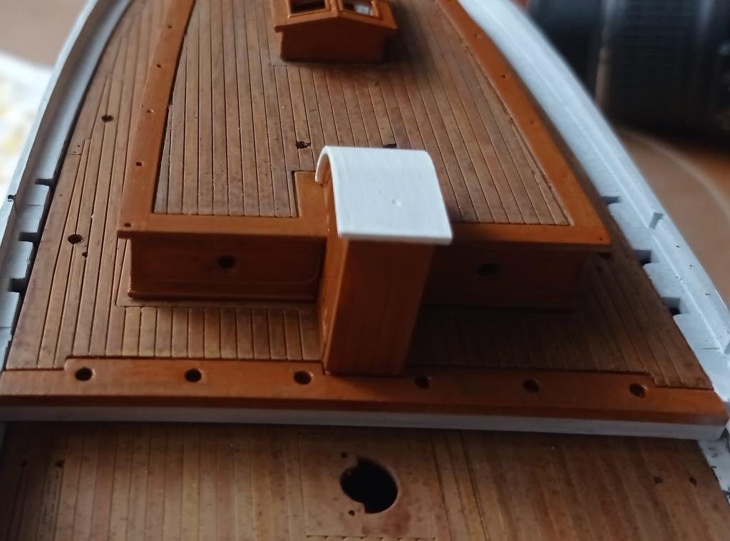
This is what I'm talking about; Beautiful colouring here but it's just a bit too dark for the deck colouring. I used burnt sienna here as I didnt have any raw sienna and dont really have the skill to reliably mix my own. and I am terrible at remembering what a colour should look like. (Off shopping in a moment!). Here, a much better colour match with the deck and, I think, close-ish to raw sienna, but I lost the 'graining/texture'. But here you can also see that 'spotting' effect from the ink. I think it's a bit like the wear and tear marks you get on any wood surface from being walked on for years and years.
- 444 replies
-
- 5
-
-
- Cutty Sark
- Revell
- (and 2 more)
-
Just got a re-issue version for £40 on eBay, sounds like I got very lucky - I was the only bidder! Very excited to see it when it arrives, looks like a very interesting kit, though I won’t be starting it for quite a while.
-
3d printing process
Kevin-the-lubber replied to henrythestaffy's topic in 3D-Printing and Laser-Cutting.
I’ll have to try that Phrozen water washable. I tried the elegoo version once and didn’t like it at all, as the surface quality was quite inferior, but I spend a fortune on IPA and would love to avoid that cost. It sounds similar to the elegoo ABS-like. I get really crisp detail with this, it’s very flexible and a fair amount of the stuff I’ve printed is very thin (0.2 - 0.4mm). I settled on grey as a standard colour as everyone says it’s the best for seeing the detail before painting. That’s certainly true in comparison to the syratech fast, which I originally could only find in a kind of skin tone. I’ve thought I’ve sanded support marks out, primed, then had to sand again, which I hardly ever had to do with grey. what settings do you use for the anycubic standard? I have most of a litre which I’ll want to use up if I can. -
Process, me, hah! I’m like a toddler at nursery, splash splash splosh, sometimes it comes out nice, sometimes not :-). I think it’s a subliminal rebellion against the rigorous methodology of the day job! Seriously, I’m going to spend some of today doing a whole series of test cards from different primers up, as I’ve had some lovely results that just need tweaking to go with my deck tone. Here’s the general direction I’m going in for teak: yellow ochre base, raw sienna next, then an orangey ink wash, then varnish. I guess it’s no coincidence that the paints are earth colours, a wood look being the goal. Bill, I borrowed Marc’s approach to use on my deck. I painted much the same as you, using the Vallejo wood kit, then instead of finishing with a grey wash as they suggest, I washed with peat brown artists ink, then Matt varnish. Originally I just wanted the ink to bring out the plank lines but learned that, if allowed, the pigment coalesces wherever there is a surface imperfection, giving a random pattern of very fine dots and tiny streaks, which I think adds texture. I also learned that, if allowed, the pigment can concentrate in big splotches, spoiling the whole thing - but you can easily take it off with a wet brush and start again. I can’t say I’ve mastered avoiding that; it’s easy on big things like the deck, harder on small parts like the pin rails, skylight etc. Personally, I’m really enjoying learning how to paint and now think I understand why the 3D market is saturated with people who just buy ready-designed miniatures, print them and then spend weeks on the painting. Another swerve - I bought a Revell 1:96 USS Kearsage on eBay this week, for later. I was the only bidder so got it at the quite modest starting price. As far as I can gather it’s long out of production and build logs seem thin on the ground. I know very little about it but it looks like it’ll be similar in complexity to the CS.
- 444 replies
-
- 2
-
-
- Cutty Sark
- Revell
- (and 2 more)
-
Looking good Bill, fabulous in fact - very busy in there. Step 28... completely missed that too. But I did manage to download a much, much cleaner copy of the Heller instructions along the way The shrouds look fantastic from an end view, very in keeping scale wise etc.
-
3d printing process
Kevin-the-lubber replied to henrythestaffy's topic in 3D-Printing and Laser-Cutting.
Try the elegoo resins. Honest, I’m not on a commission nor some sort of elegoo evangelist but I had my printers running in my office for months without it becoming noticeably smelly, as the garage is unheated.I had to move them back into the garage when I started using the sirayatech as that does have a sickly sweet, slightly foul odour. IPA is also quite smelly so I’ve always done the cleanup in the garage, but the smell has become much less of an issue since I bought the anycubic wash and cure machine. And also way less messy. Though more expensive, I think, as I’m fouling a gallon of IPA at a time now rather than just small amounts as I go along, and eventually have to exchange it for clean stuff. -
And so quickly! It would probably take me days to get that piece right in 3D printing and it wouldn’t be better.
- 2,699 replies
-
- 7
-
-
- heller
- soleil royal
- (and 9 more)
-
No sign of them on the IMAI instructions either. A design change as they went along, meaning now surplus to requirements?
