Check out our new MSW Sponsor Innocraftsman
×


Rick310
-
Posts
753 -
Joined
-
Last visited
Content Type
Profiles
Forums
Gallery
Events
Everything posted by Rick310
-
Congratulations Vlad!! I have really enjoyed following your blog and have learned much your build!! she’s magnificent!! Rick
-
Ed, On the YA, was the he mizzen mast a single tree or was it a made mast on your model? If a single tree, why the decision to place mast bands? I seem to recall that I read somewhere that bands were place on single tree mast for strength. I am currently building the Flying Fish and it supposedly had a single tree mast and the plans show no bands on the mizzen. However, 2 contemporary paintings ( Buttersworth and China Trade) show bands on the mizzen. what to do? Rick
-
Beautiful! Rick
-
Merry Christmas Keith, Really enjoy watching your progress! Enjoy your grandchild! Rick
-
George, For questions you can always call Nic or Al Ross at Bluejacket. Nice start to the model. Rick
-
Should be a fun build George, I’ve seen the completed model at Bluejacket and it’s quite attractive!! Rick
-
Really looks great George!! You did a magnificent job!! Rick
- 602 replies
-
- 1
-

-
- Flying Fish
- Model Shipways
- (and 2 more)
-
Beautiful work!! Rick
-
Beautiful!!!
-
Well done!! Rick
-
Good luck with your build. Nic’s (Mr Bluejacket) model of the Red Jacket is beautiful!! Maybe Nic can send you pictures. I use his model as a reference for my Flying Fish! Rick
- 152 replies
-
- 3
-
-
- Red Jacket
- Marine Model Company
- (and 2 more)
-
Thanks George!
-
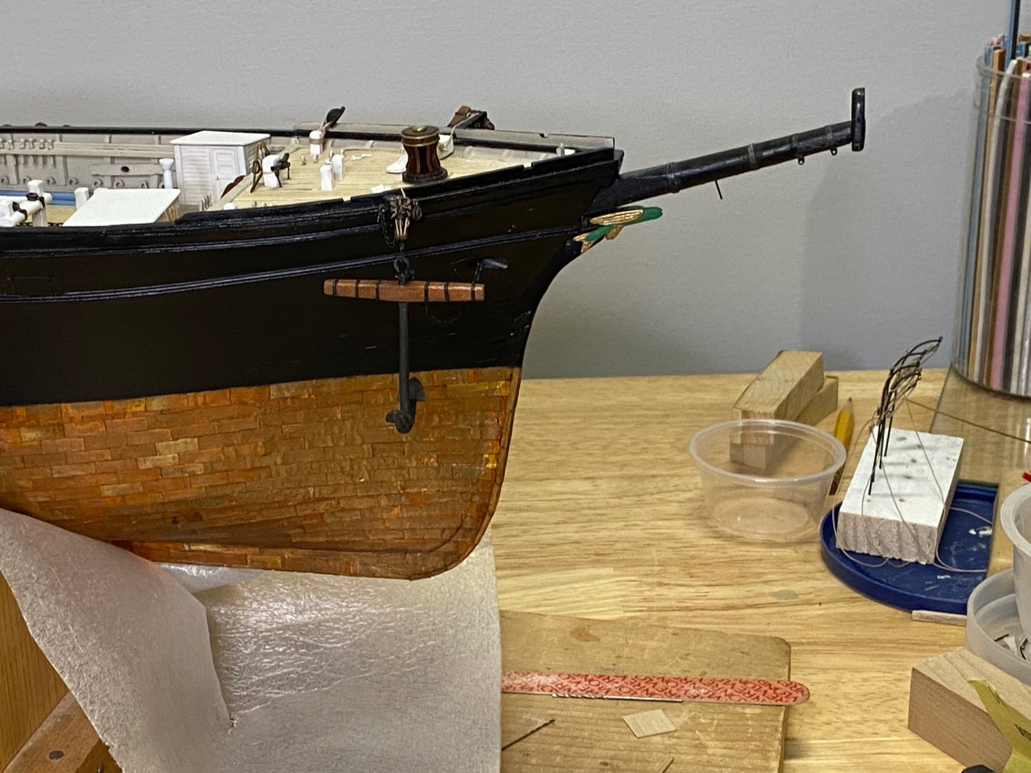
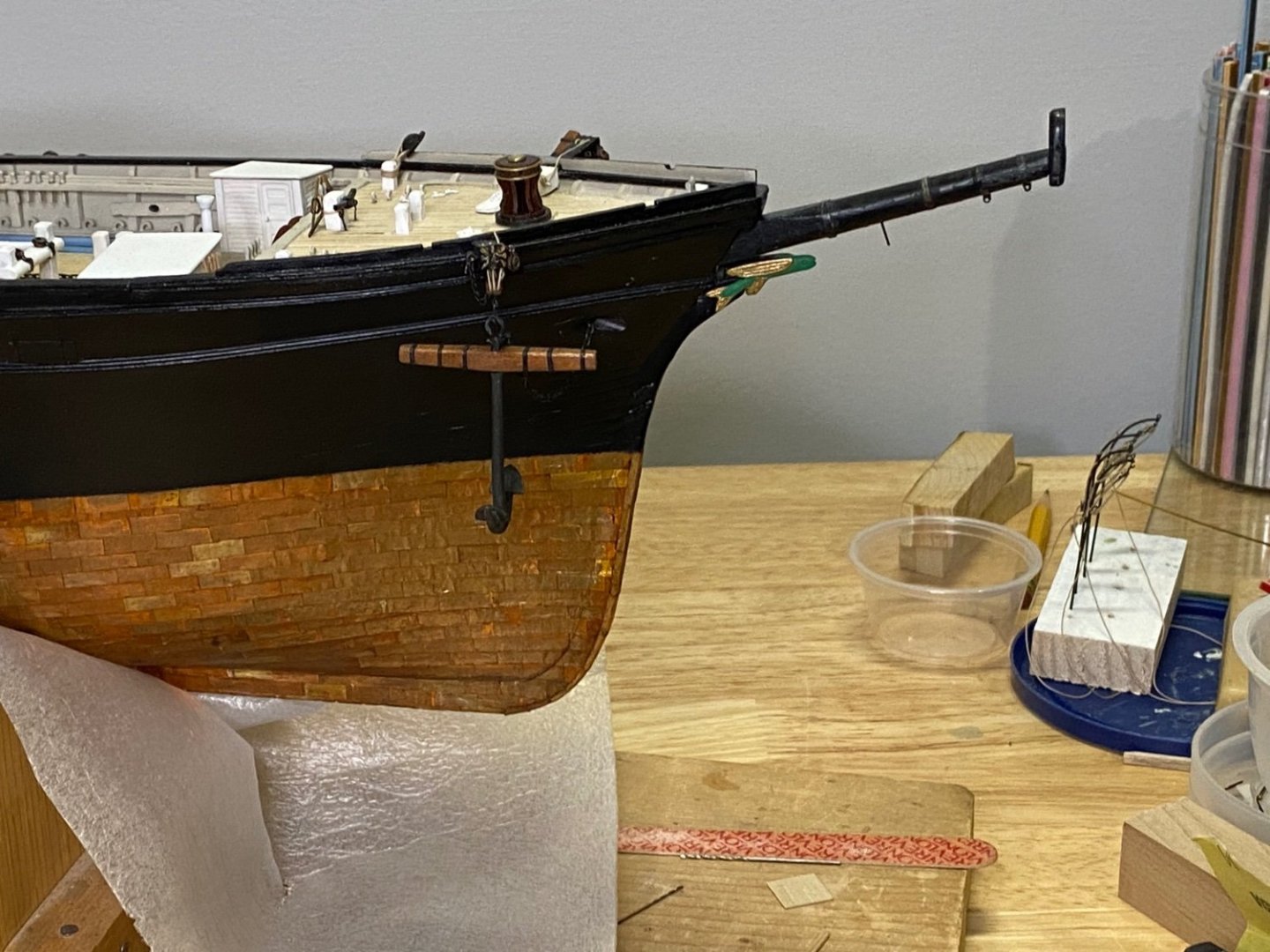
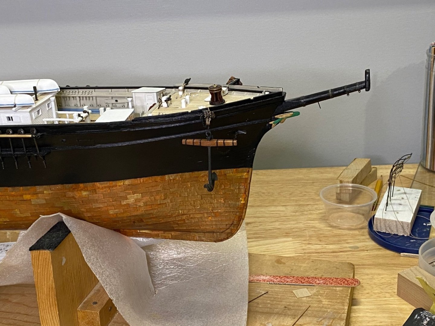
Here are some better pictures of the bow showing more of sweeping arc of the stem and figurehead . Rick
- 343 replies
-
- 1
-
-
- Flying Fish
- Model Shipways
- (and 1 more)
-
Thanks George!! you did a magnificent job on your Flying Fish!! I also really appreciate your blog as I have used it for a reference frequently as I slowly progress! Thanks again for your kind words. Rick
-
Rob, Thanks for your input. In examining both contemporary paintings, I don’t see a definitive naval hood on the Flying Fish. Given that there are several decades separating the launch of the FF and Glory, could the naval hood represent a further development of the bow/ stem/ cut water of Mc Kay’s ships? Certainly Glory’s is substantial. On my model, I tried to show an extended stem/ cut water to more closely match the Buttersworth’s painting, ie the graceful arc of the stem as opposed to the stem the plans show which is more straight up. Rick
-
I bought the Byrnes table saw 16 yrs ago and it is worth every penny!! Absolutely could not make the Flying Fish without it!! I’ ended up milling almost all of my wood stock as the wood supplied with the kit is inadequate! Jim Brynes takes an occasional break but his table saw is still available, Rick
-
WOW. Beautiful metal work!!! Rick