Rick310
-
Posts
833 -
Joined
-
Last visited
Content Type
Profiles
Forums
Gallery
Events
Everything posted by Rick310
-
Beautiful as always Keith!! Rick
-
Jared, For what it’s worth, I like smaller line better even though it’s more difficult to work with. I’ve always heard it said that it is better to be too small than to be too large. Good luck, FF is coming along really well! Rick
-
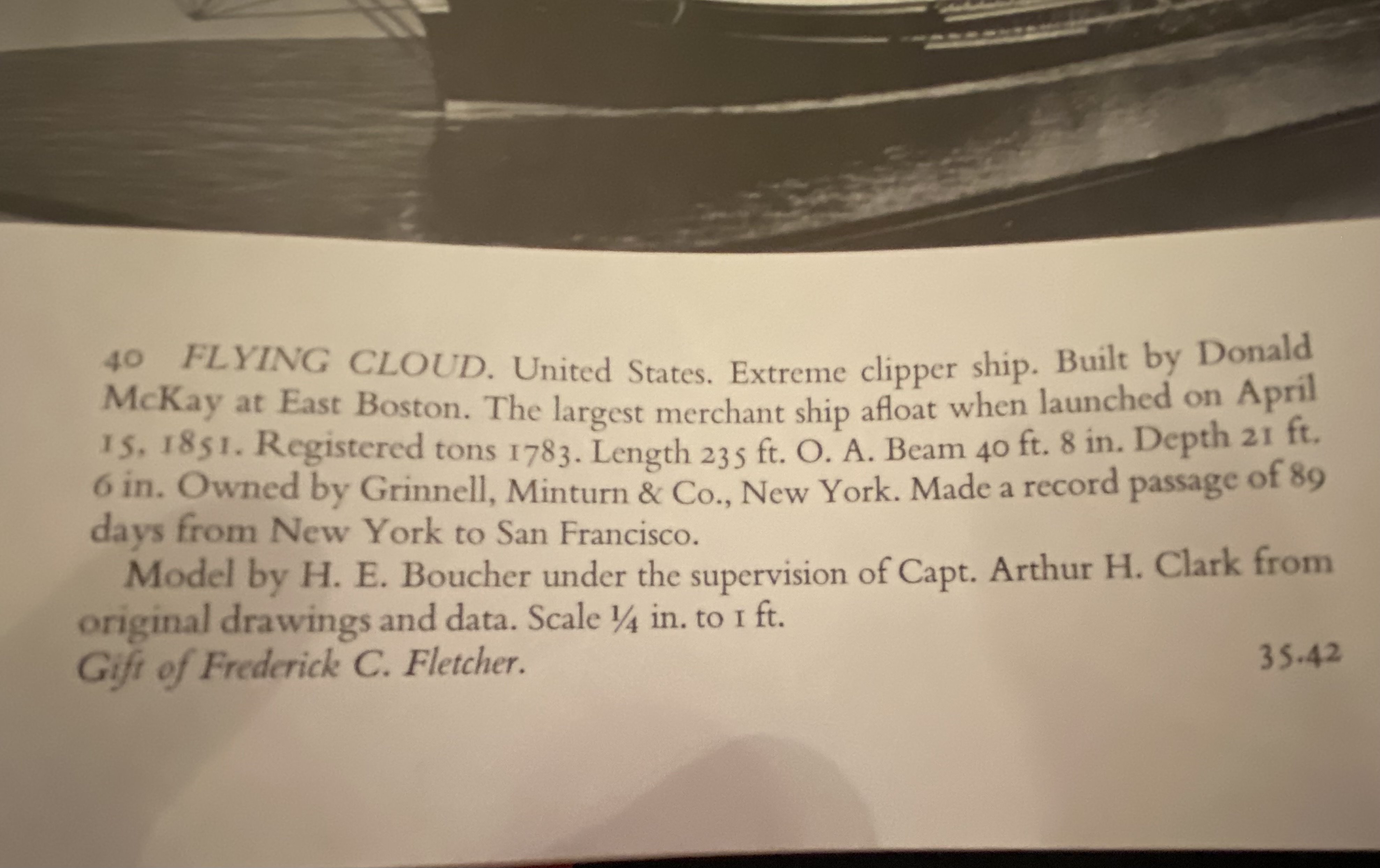
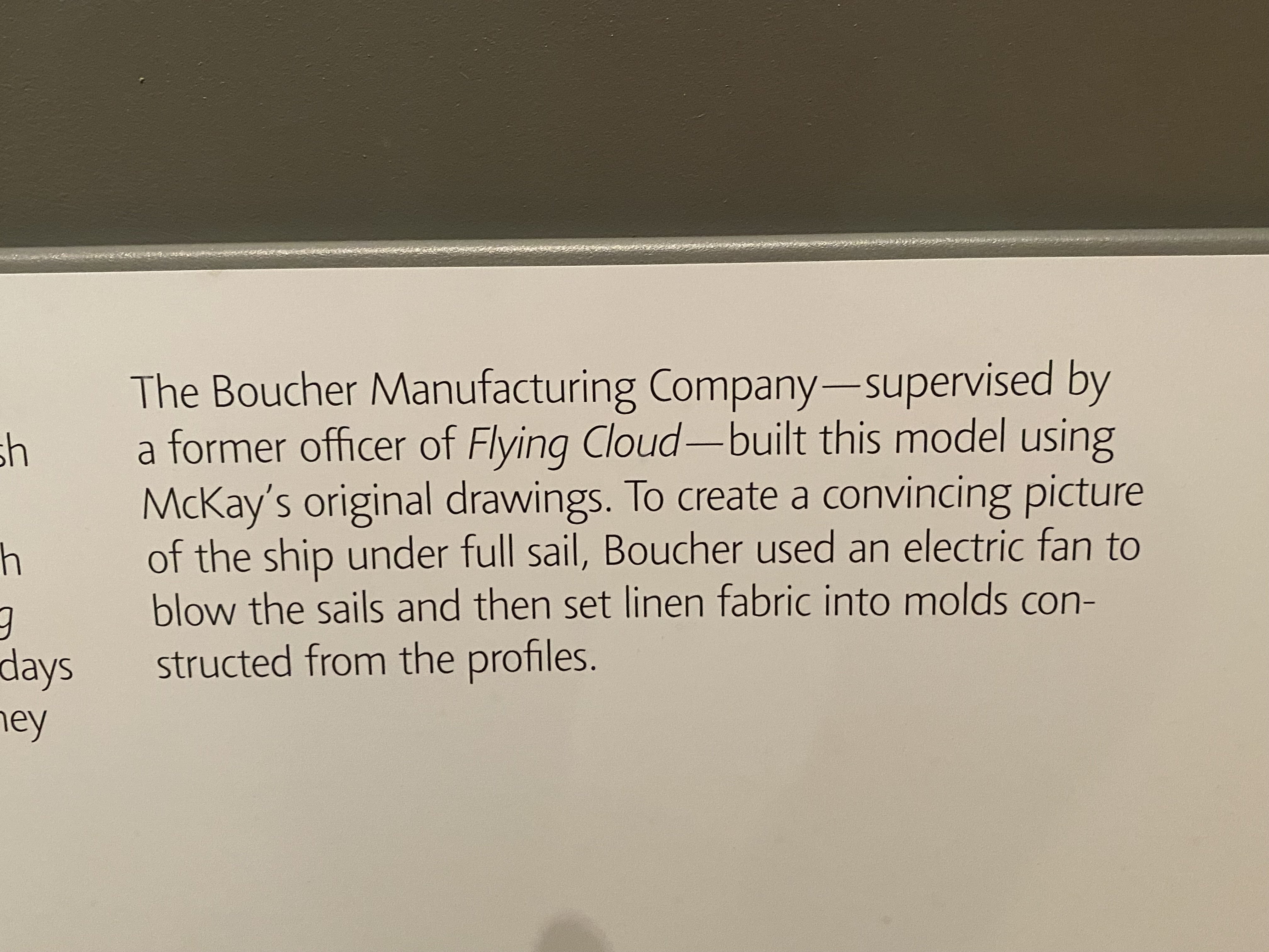
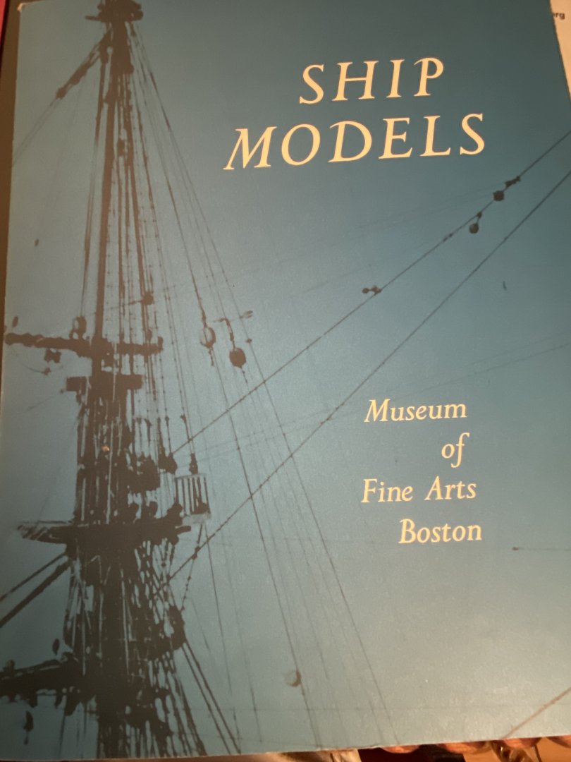
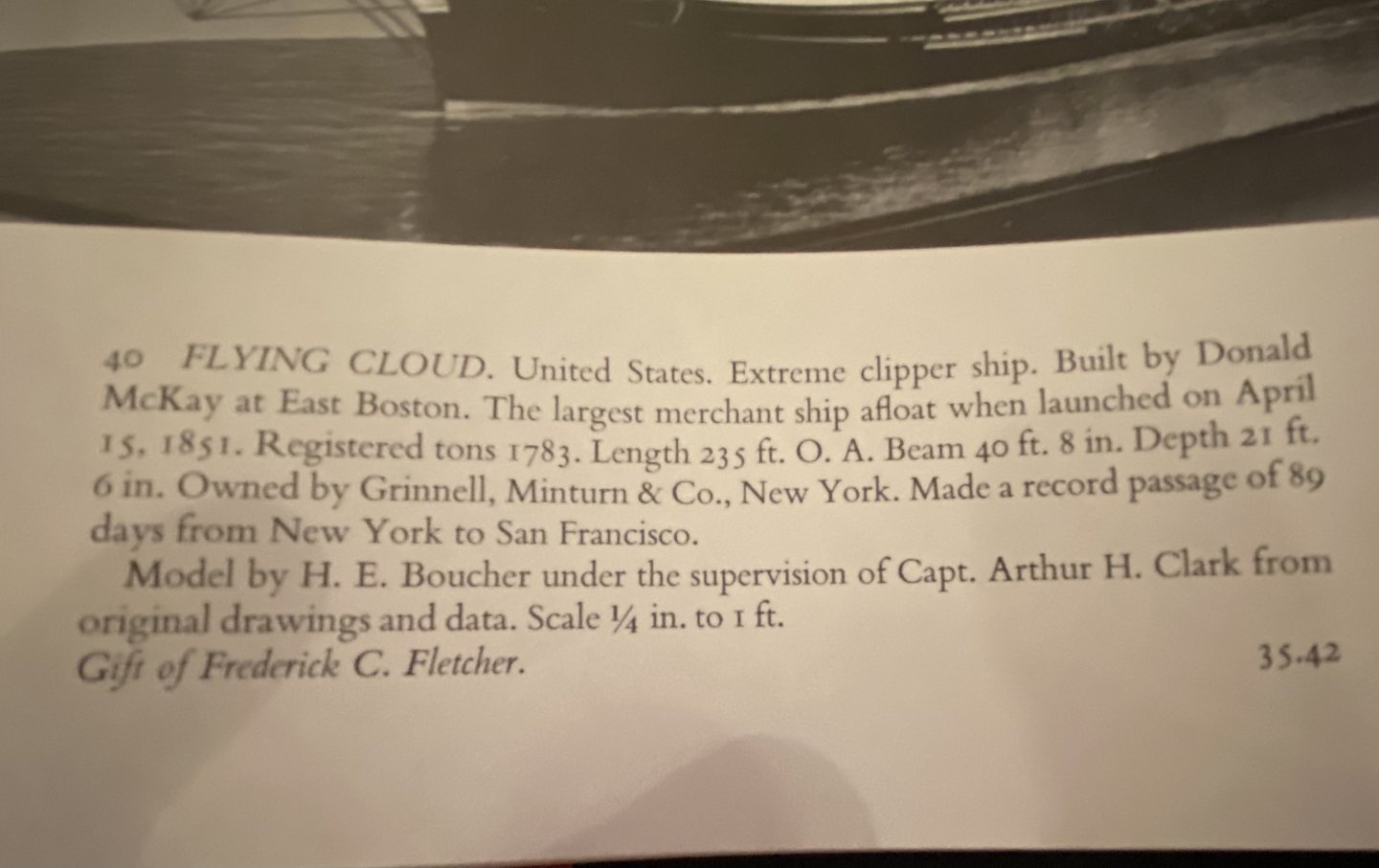
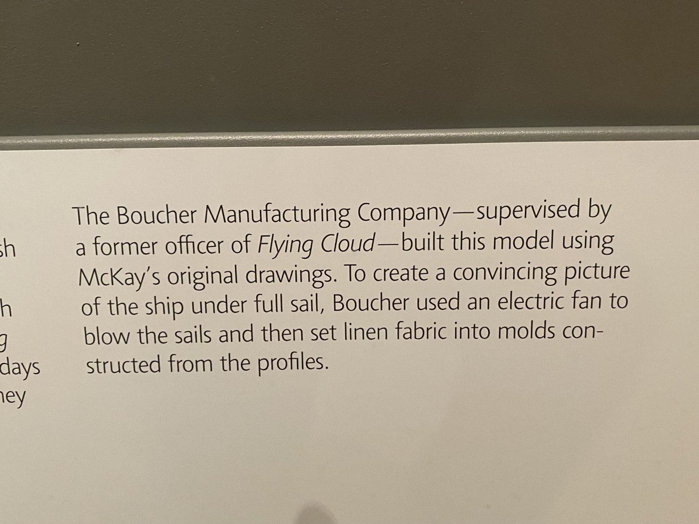
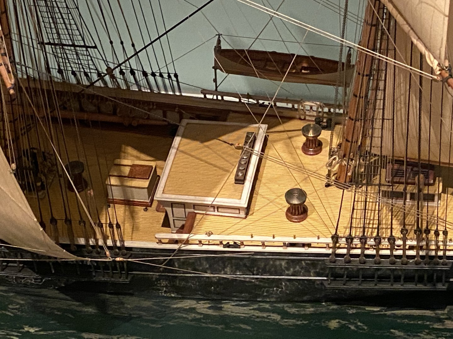
Rob, ClipprtFan, You might find this interesting. Years ago I purchased this book on the ship models on the Boston Museum of Fine Art. It contained 2 pictures of the Flying Cloud with the caption that the model was constructed under the supervision of Arthur H Clark. However, in the museum, the information plaque states that the model was constructed under the supervision of a former officer. Interesting. RickYhe bottom picture is from the actual display.
-
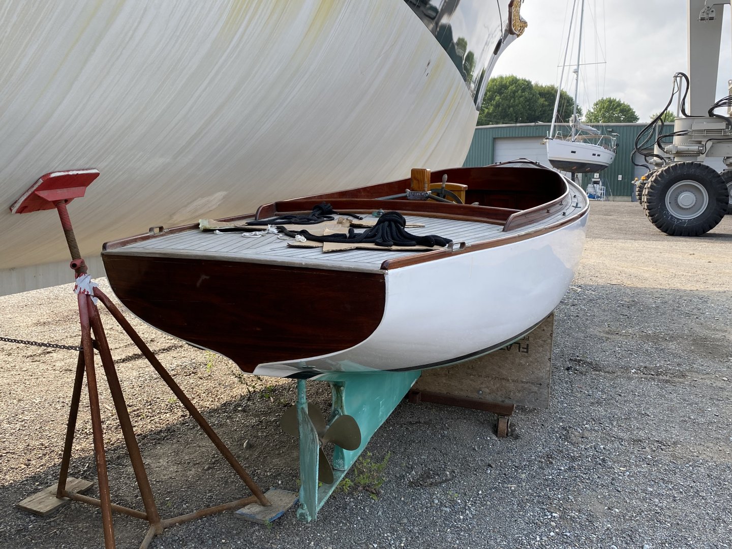
I don’t know. Don’t know why they would uncover her if she wasn’t, unless she is being moved. Rick
-
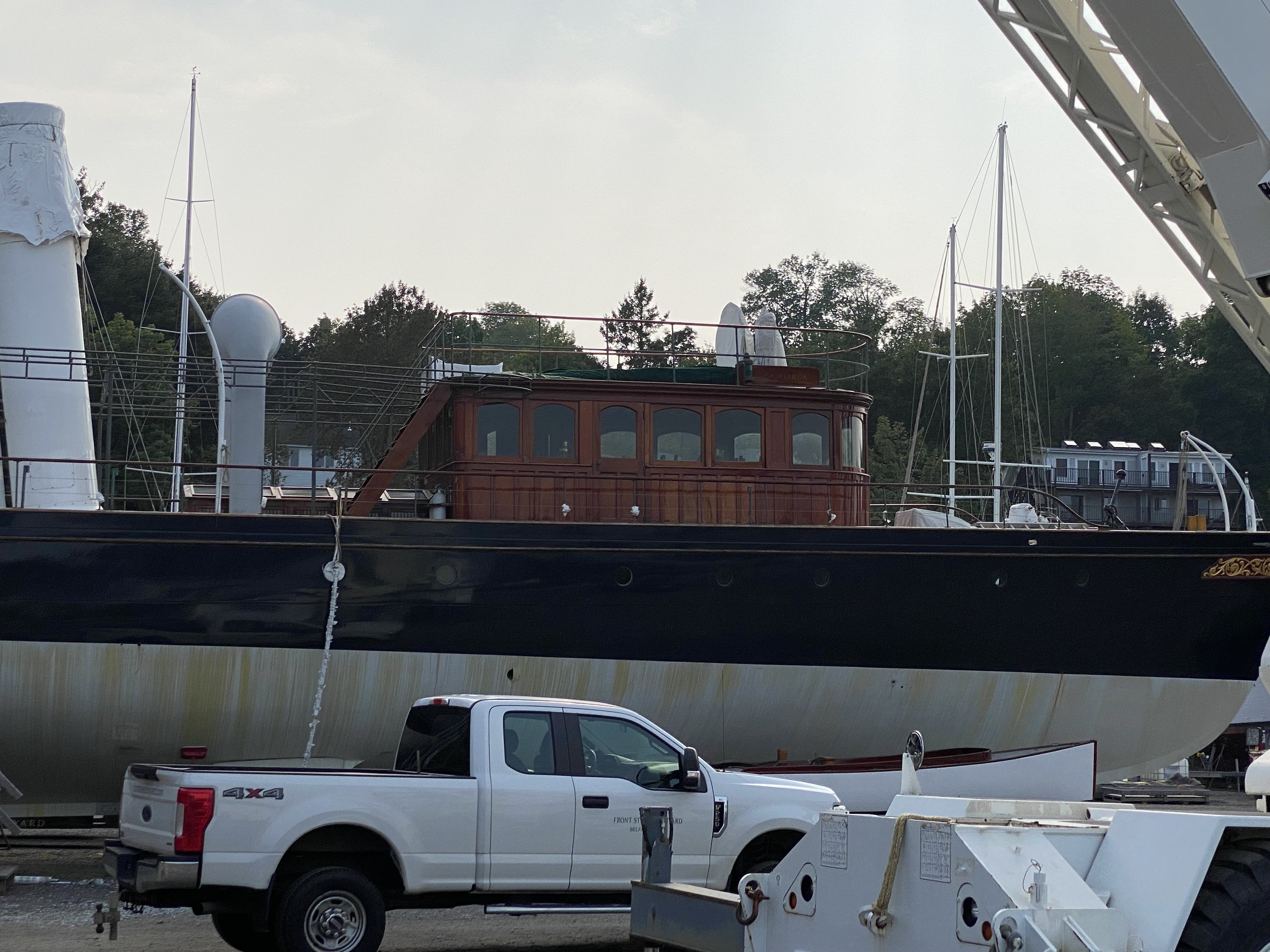
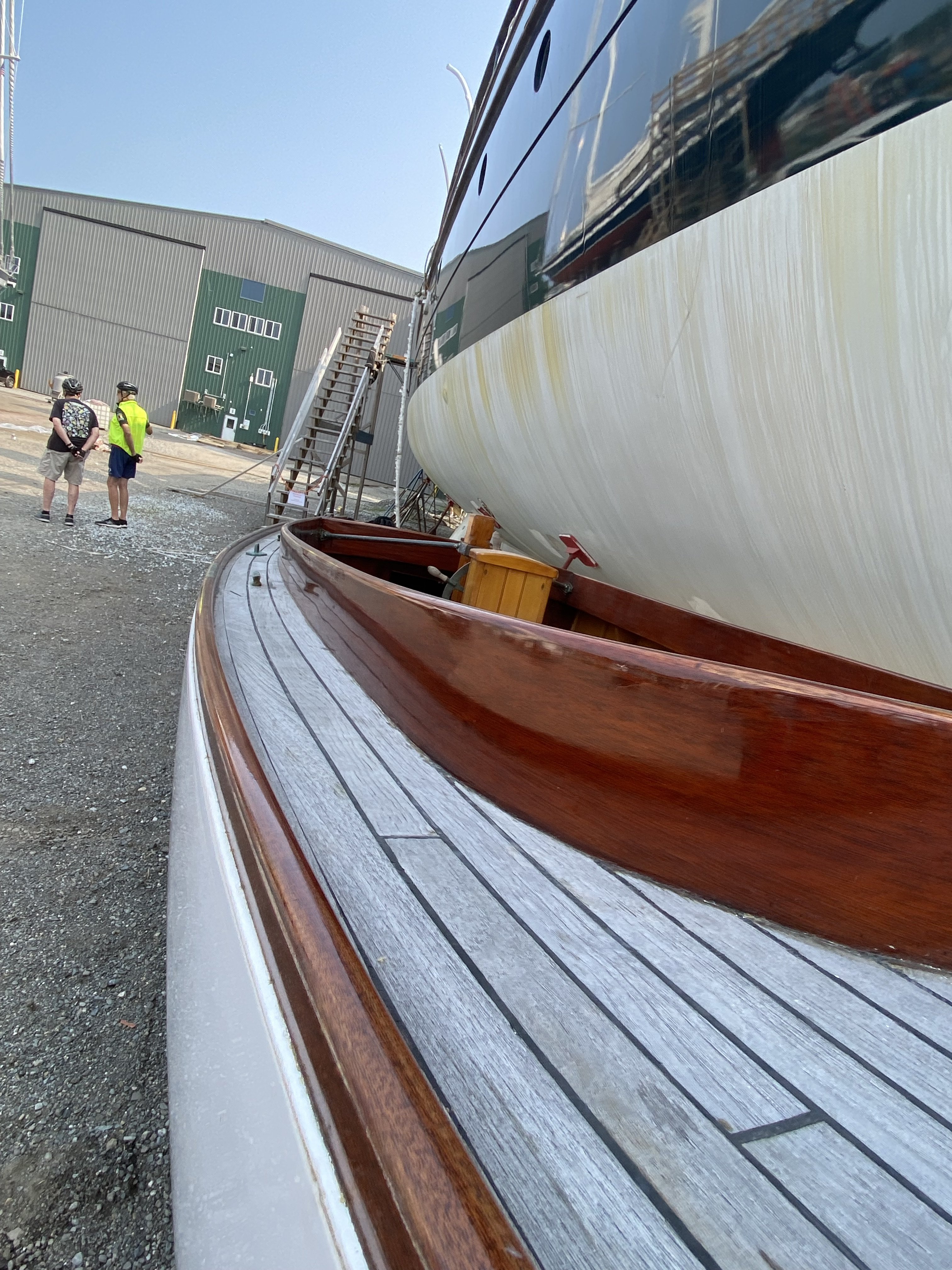
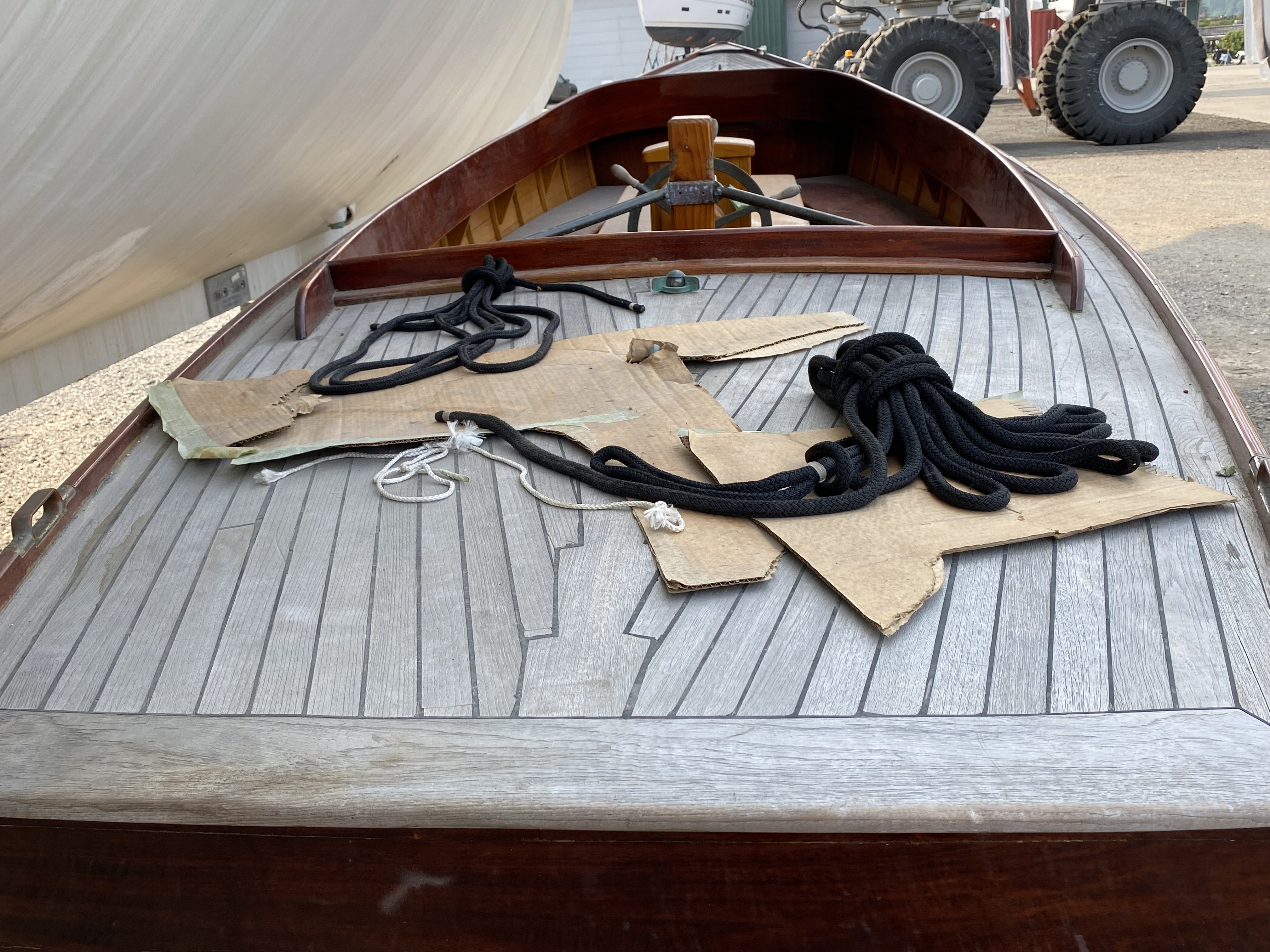
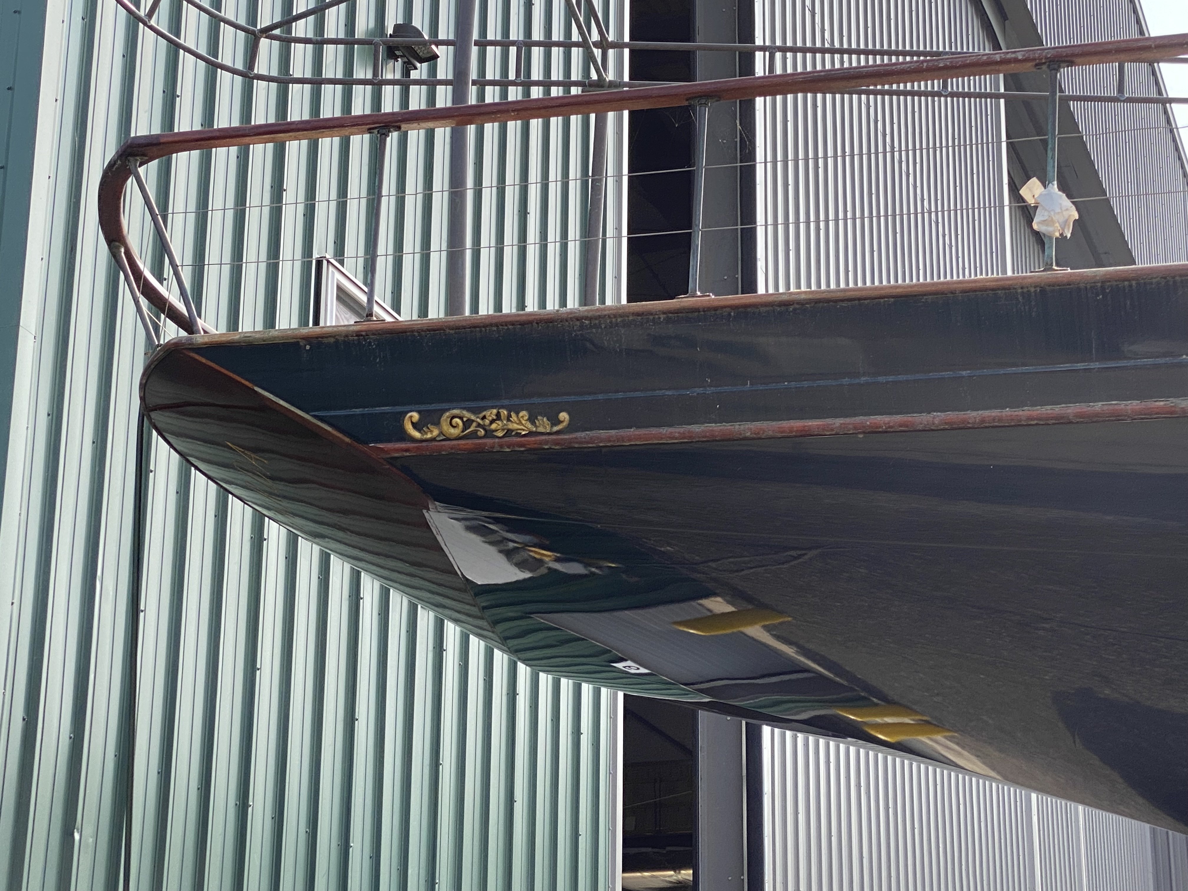
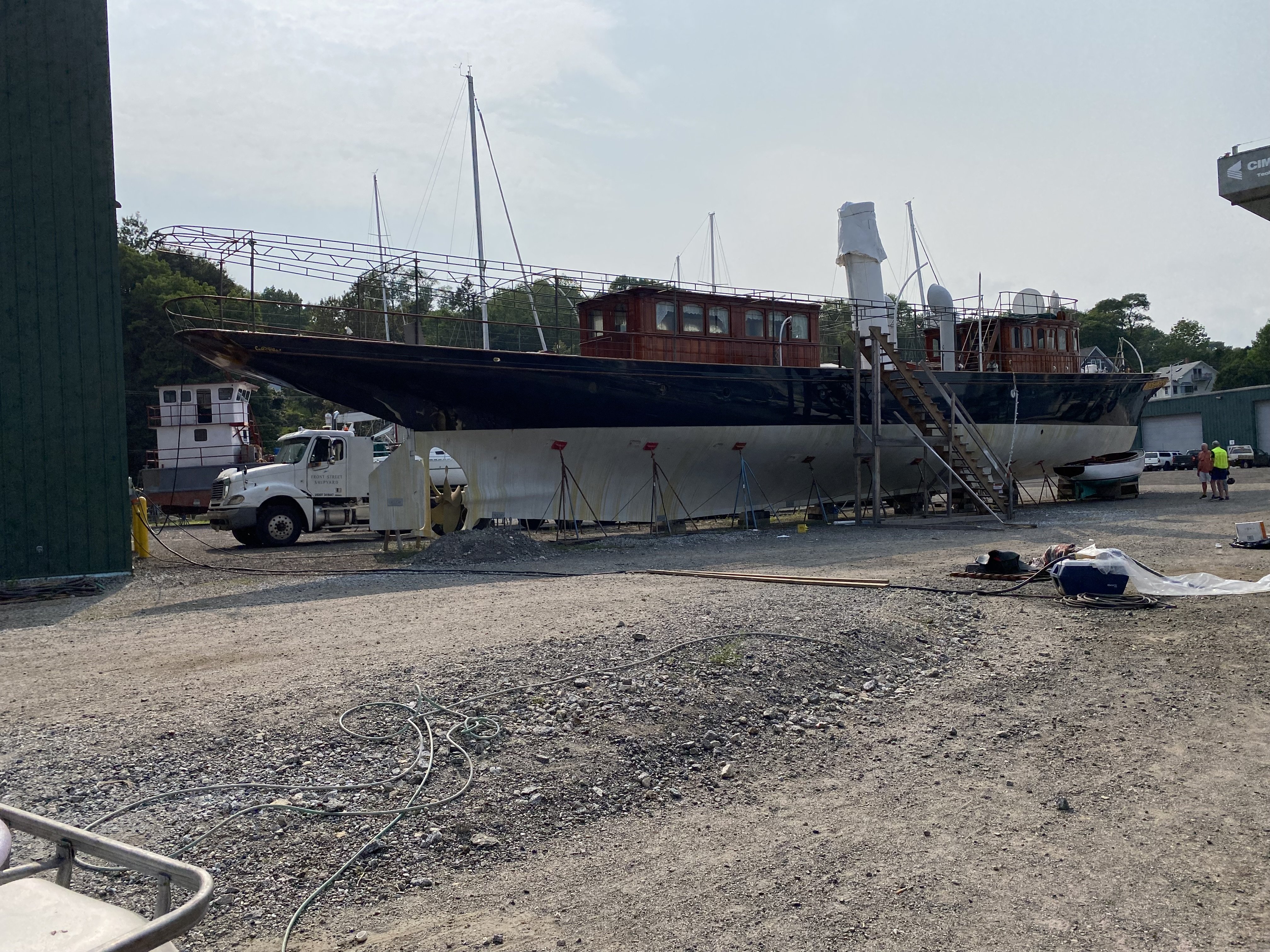
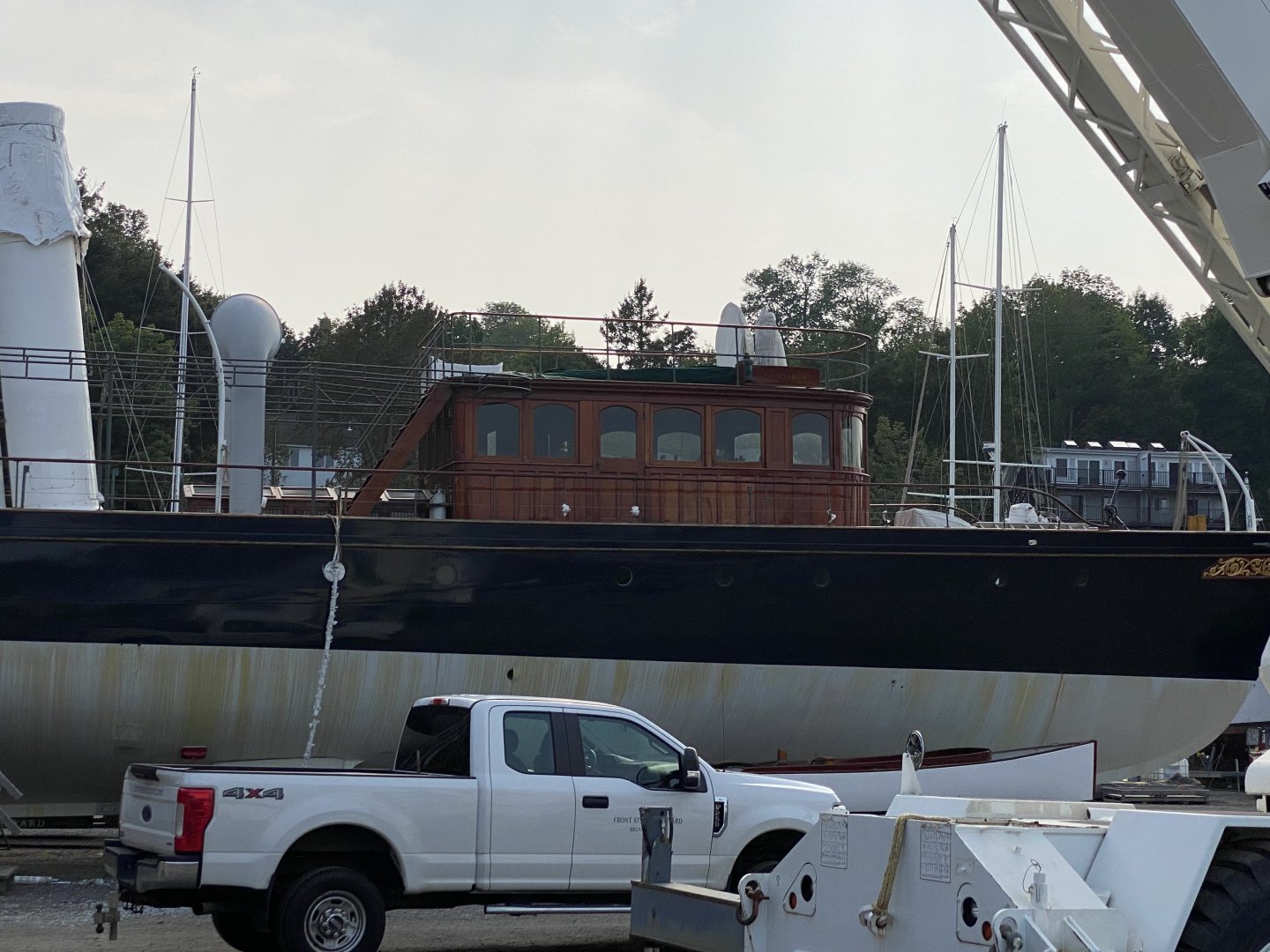
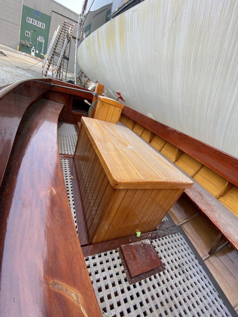
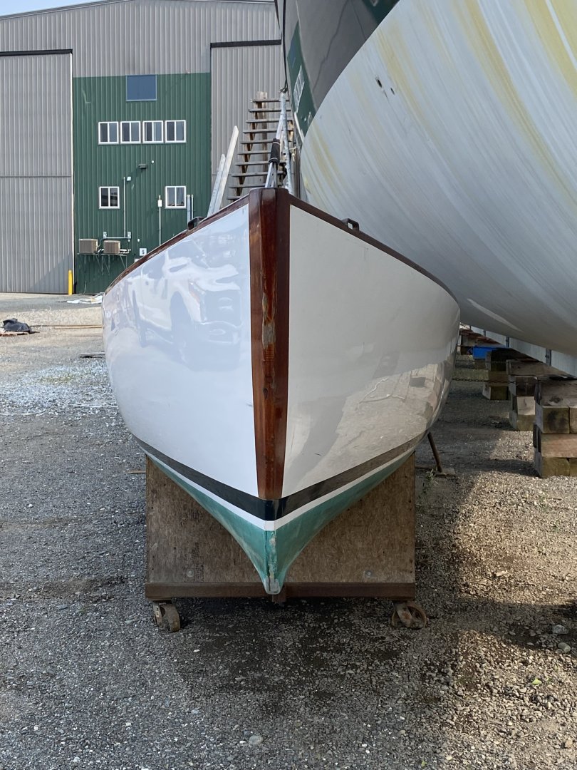
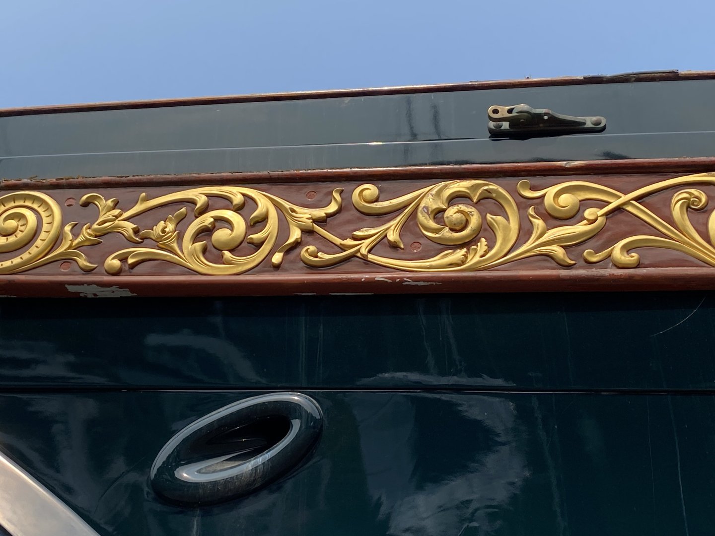
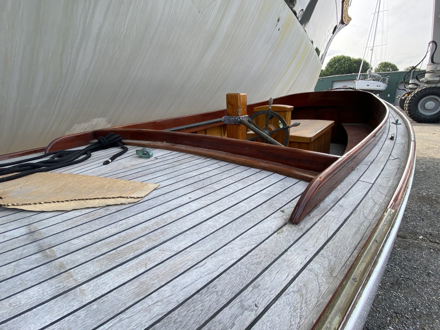
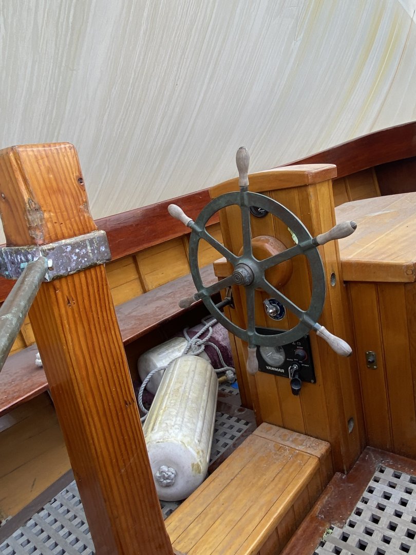
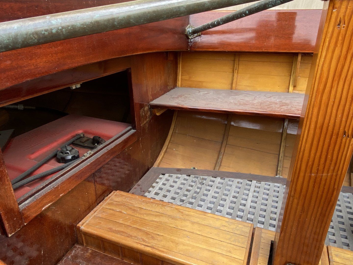
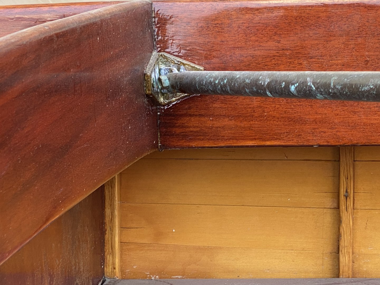
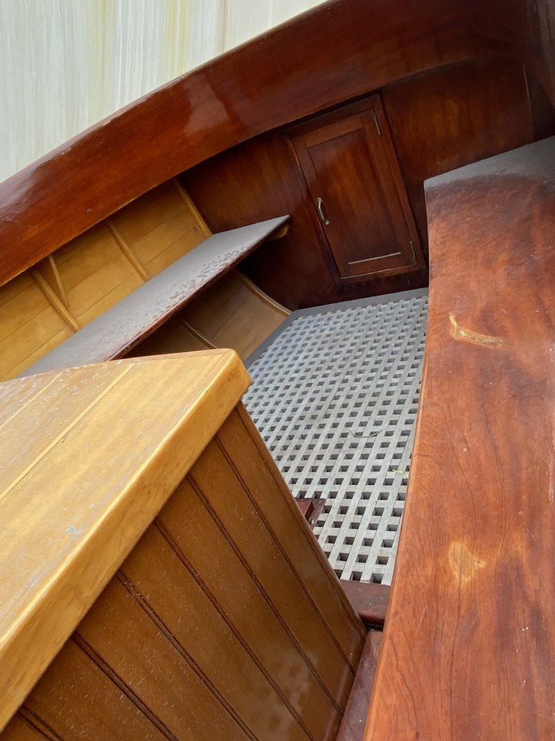
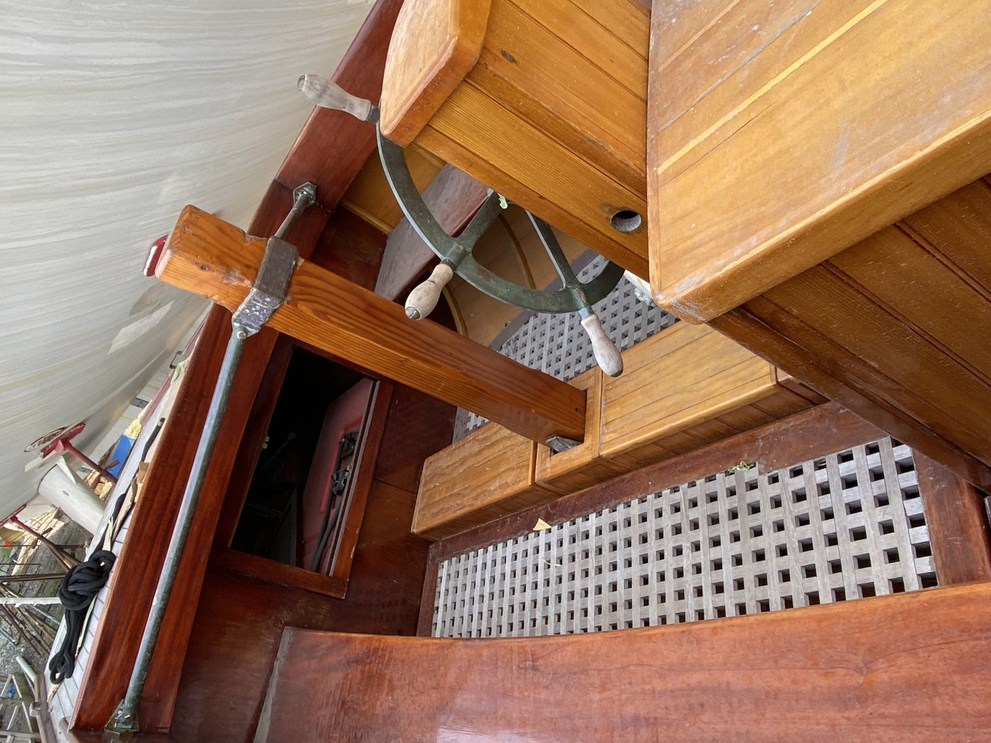
Keith, walked past Cangarda today and both Cangarda and the were uncovered. Sold? I took some additional pictures of both. Most are of the launch.


-
Rob, that looks great!! I agree with the rectangle windows on the sides and really like the curved windows on the front. Rick
-
Congrats Glen!! A fantastic project and result!! It’s been a pleasure to follow along!! Rick
- 235 replies
-
- 5
-

-

-
- Banshee II
- Bottle
- (and 1 more)
-
Beautiful drawings and portico!! Rick
-
Interesting technique of pre-bending the planks so they nest better on the transom and allowing the hull to straighten them. Rick
-
Your a brave man Keith, but a man’s gotta do what a man’s gotta do. Cangarda’s really looking great!! Rick
-
You are making a nice start on the rigging! Rick
- 431 replies
-
- 1
-
-
- Flying Fish
- Model Shipways
- (and 2 more)
-
Very nice, really coming along! Rick
-
Really looking great Keith!! Rick
-
Beautiful hull, very impressive! Rick
-
I was at Mystic about a year and a half ago. They were in the process of redoing the model ship gallery at that time. I’m sure it is on display now. Really want to see it. Rick
- 3,618 replies
-
- 2
-
-
-
- young america
- clipper
- (and 1 more)
-
Ed, Do you recall from your research if Young America had ventilators? Hope to see the model at Mystic, unfortunately it was not yet on display last time I was there. Your 3 volume series on building YA have been invaluable! Rick
- 3,618 replies
-
- 1
-
-
- young america
- clipper
- (and 1 more)
-
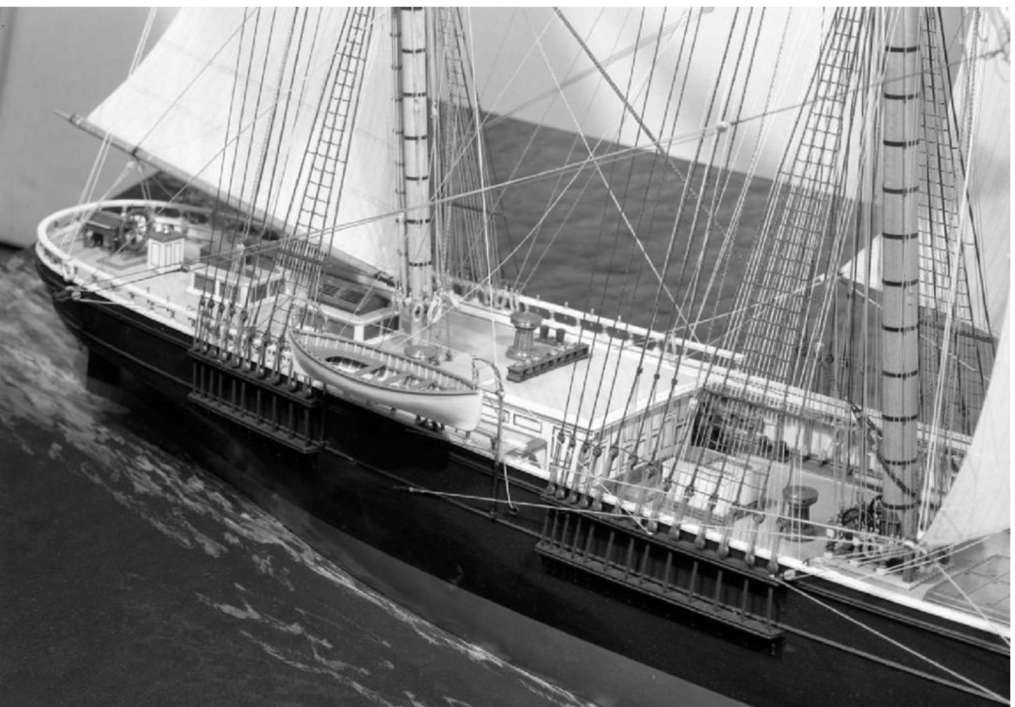
Rich, I suspect that Arthur Clark did not serve aboard the Flying Cloud, but was involved with the building of the model due to his extensive knowledge and experience, having served on clipper ships, although possibly not the Flying Cloud. This might explain the lack of first hand knowledge of the bow/naval hood as well as the ventilators.
-
Also, the model of the Challenge at the Smithsonian has both types of ventilators
-
WOW. Didn’t know that there was a second model of the Flying Cloud by Boucher. Very similar but differ with the studding sails. You are exactly correct that the Emerson ventilators were for air circulation of the holds and cabin spaces. The model in Boston lacks these ventilators as well. I read about Arthur Clark’s involvement with the building of the model in a description of the model by the museum. However, when I went to see the model, Arthur Clark was not mentioned. They did say, as I recall, that someone who had served on board the Flying Cloud had supervised it’s construction. I hope to get back to Boston to get more photos of the model in the near future and will pay more attention to the description. Rick
-
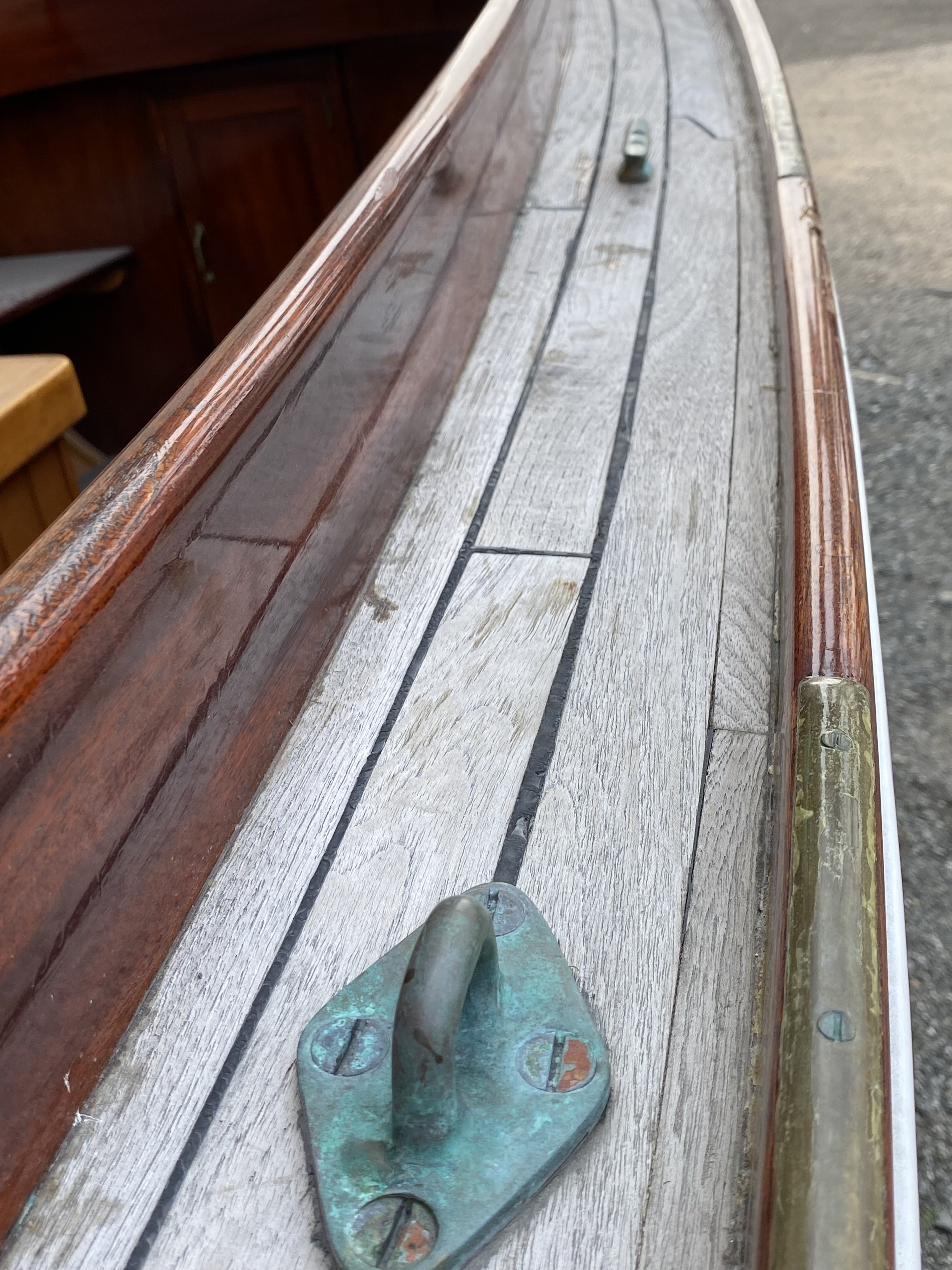
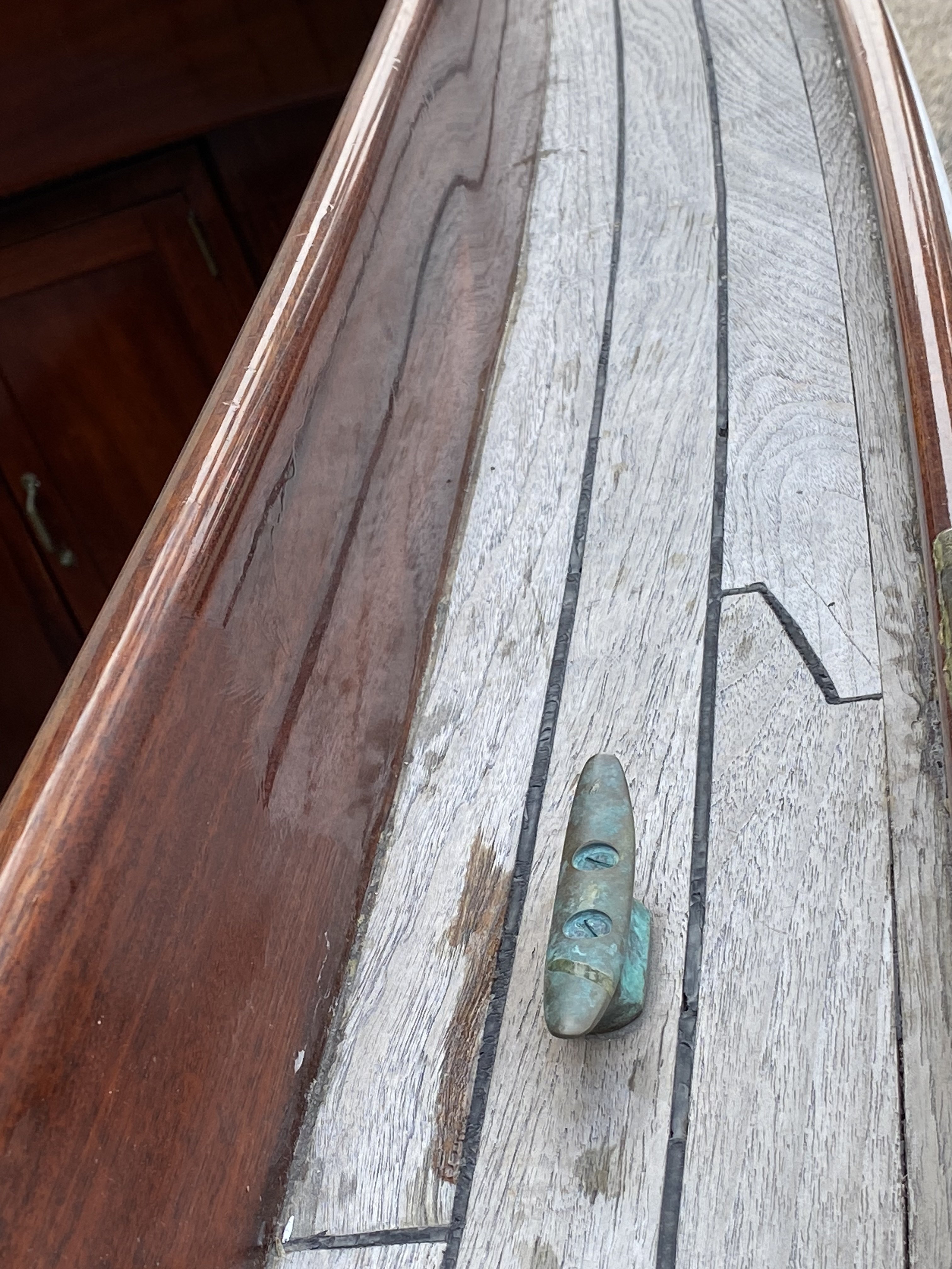
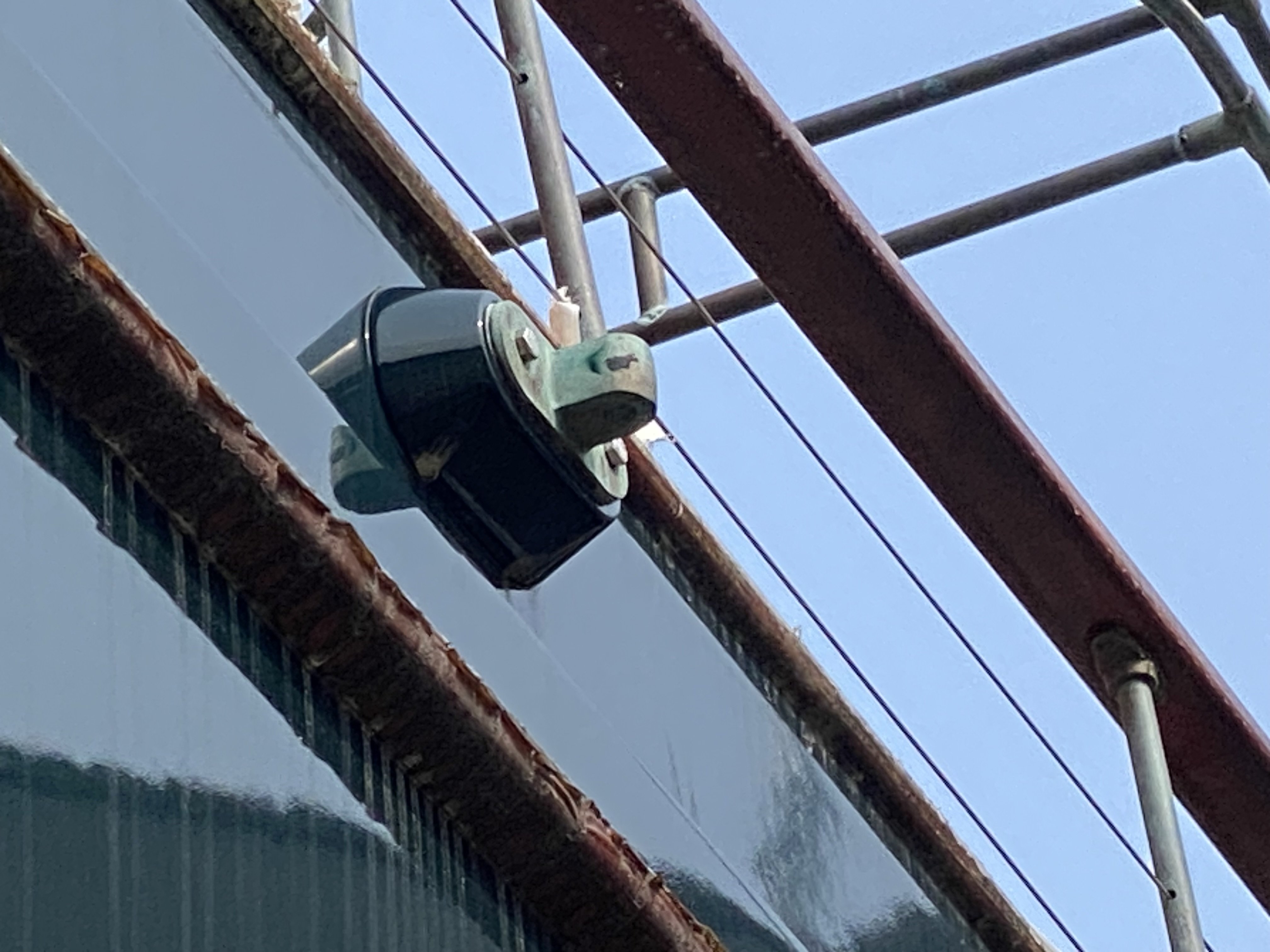
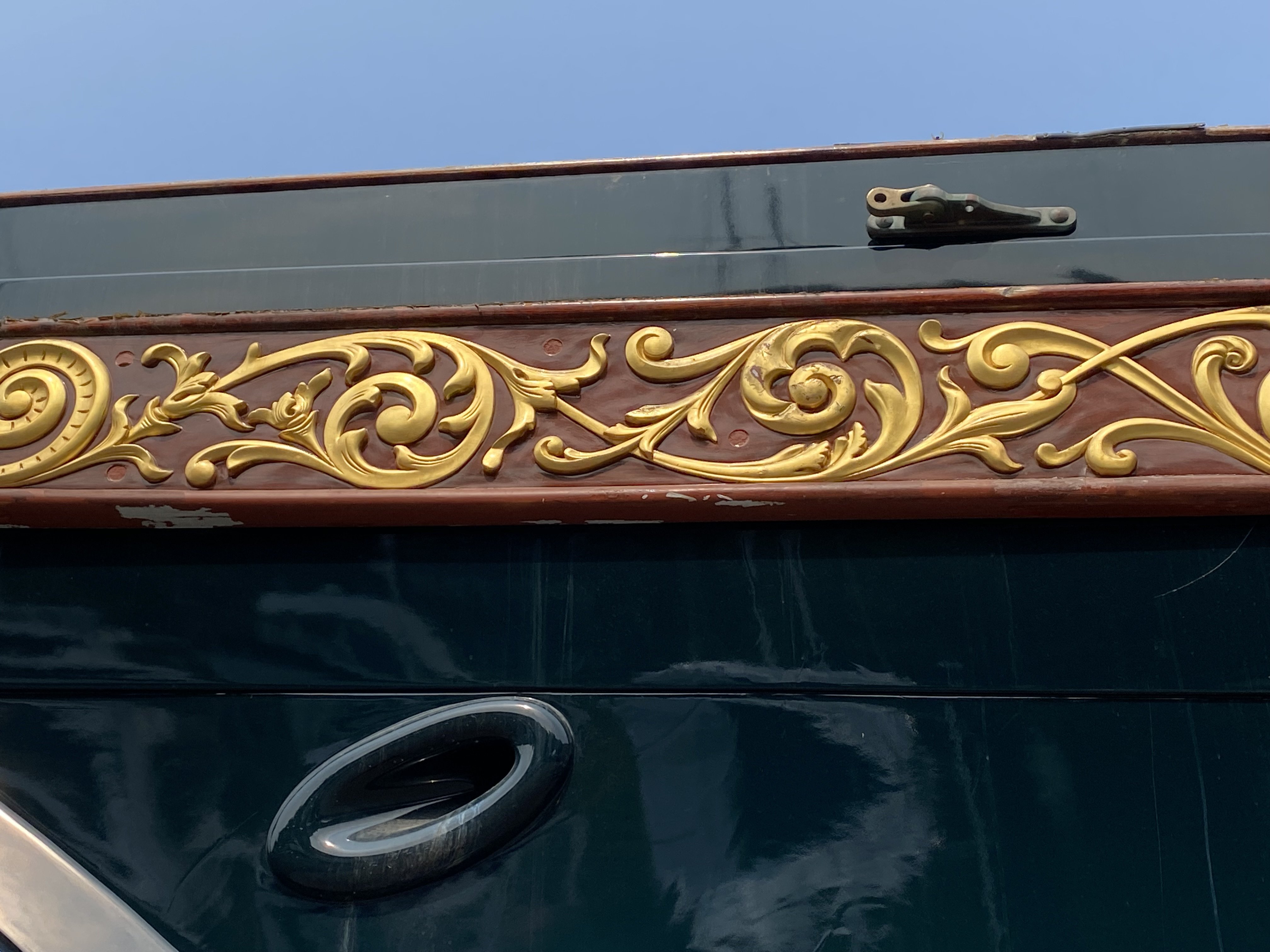
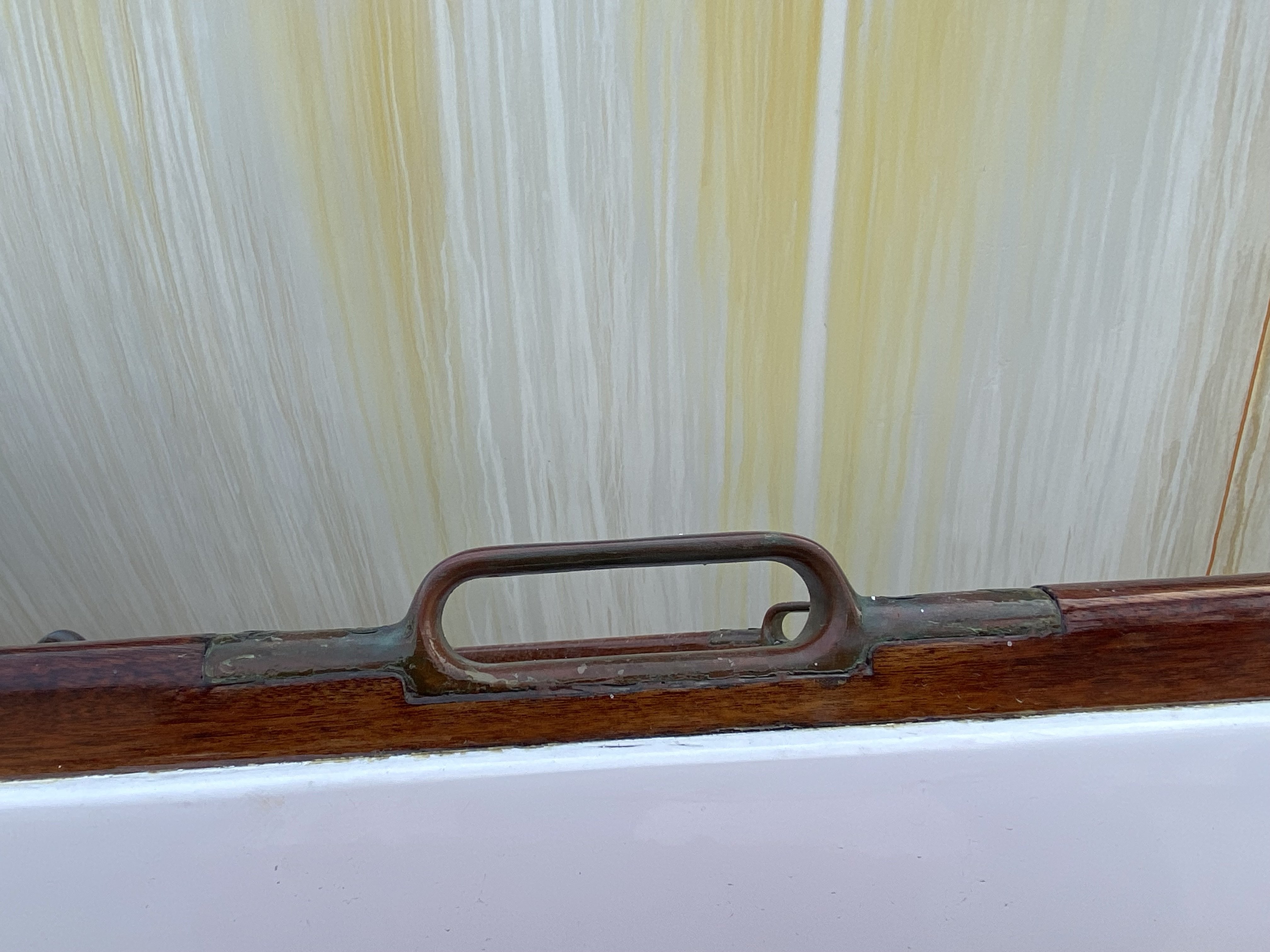
I understand that the planksheer ventilators were to allow air circulation in the air space between the frames, bounded by the hull planking on the outside, and the ceiling planking on the inside. The ceiling planking had air holes drilled into it to allow air circulation to prevent rot to the frames.
-
Clipper Fan, I just went back and looked at the pictures of the Flying Cloud in the Boston Museum of Fine Art and there is no evidence that there are ventilators in the plank sheet on the model. I understand that Capt Arthur Clark supervised the building of the model. Of course, this doesn’t mean that there weren’t ventilators, probably were but just not modeled. Whether or not the Flying Fish had gooseneck ventilators or straight is open to debate that hopefully further research will elucidate. I believe that the gooseneck ventilators on the FF were chosen as the only known model that has them is the Challenge in the Smithsonian. I also keep in mind that the list of contributions to the FF plans by Ben Lankford is a very distinguished list, including Eric Ronnburg
-
Completely agree with Rob, keep them black! Rick
-
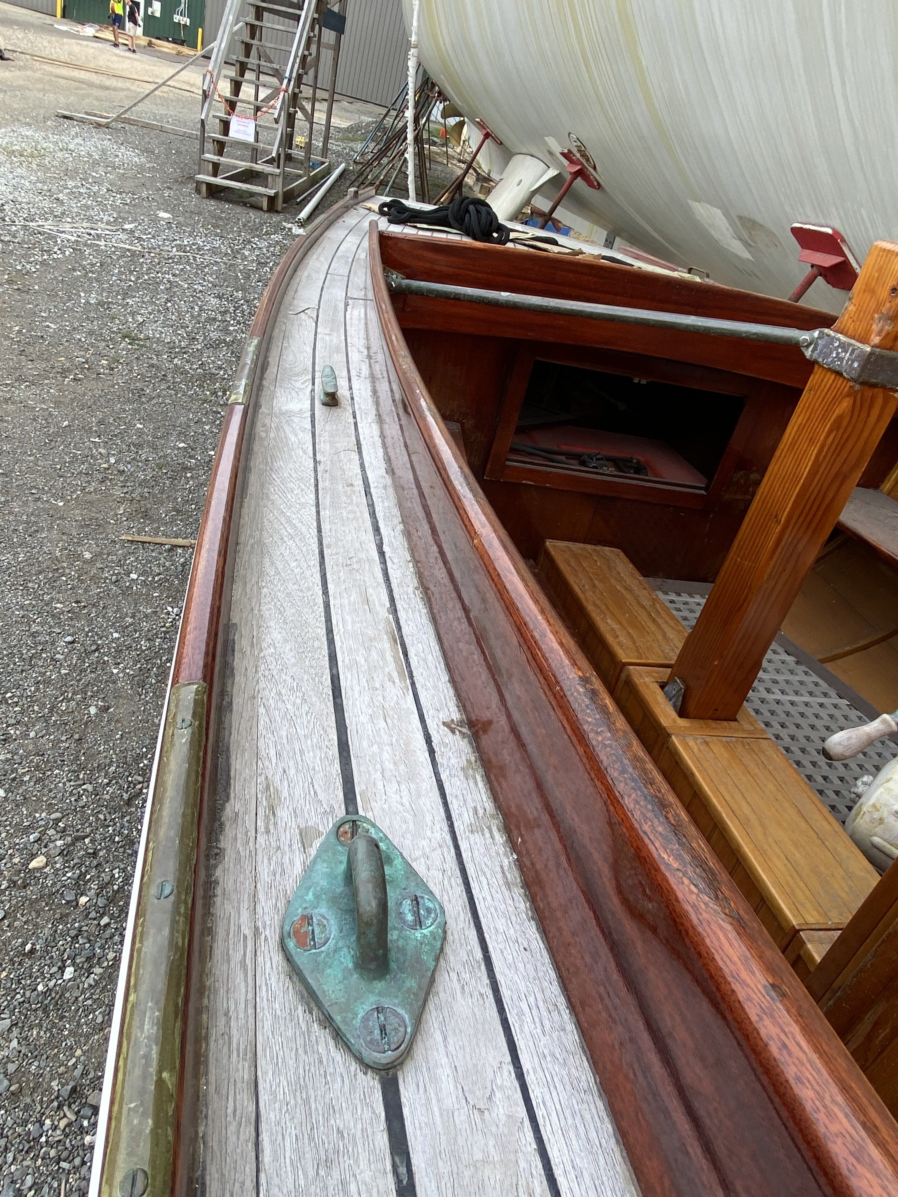
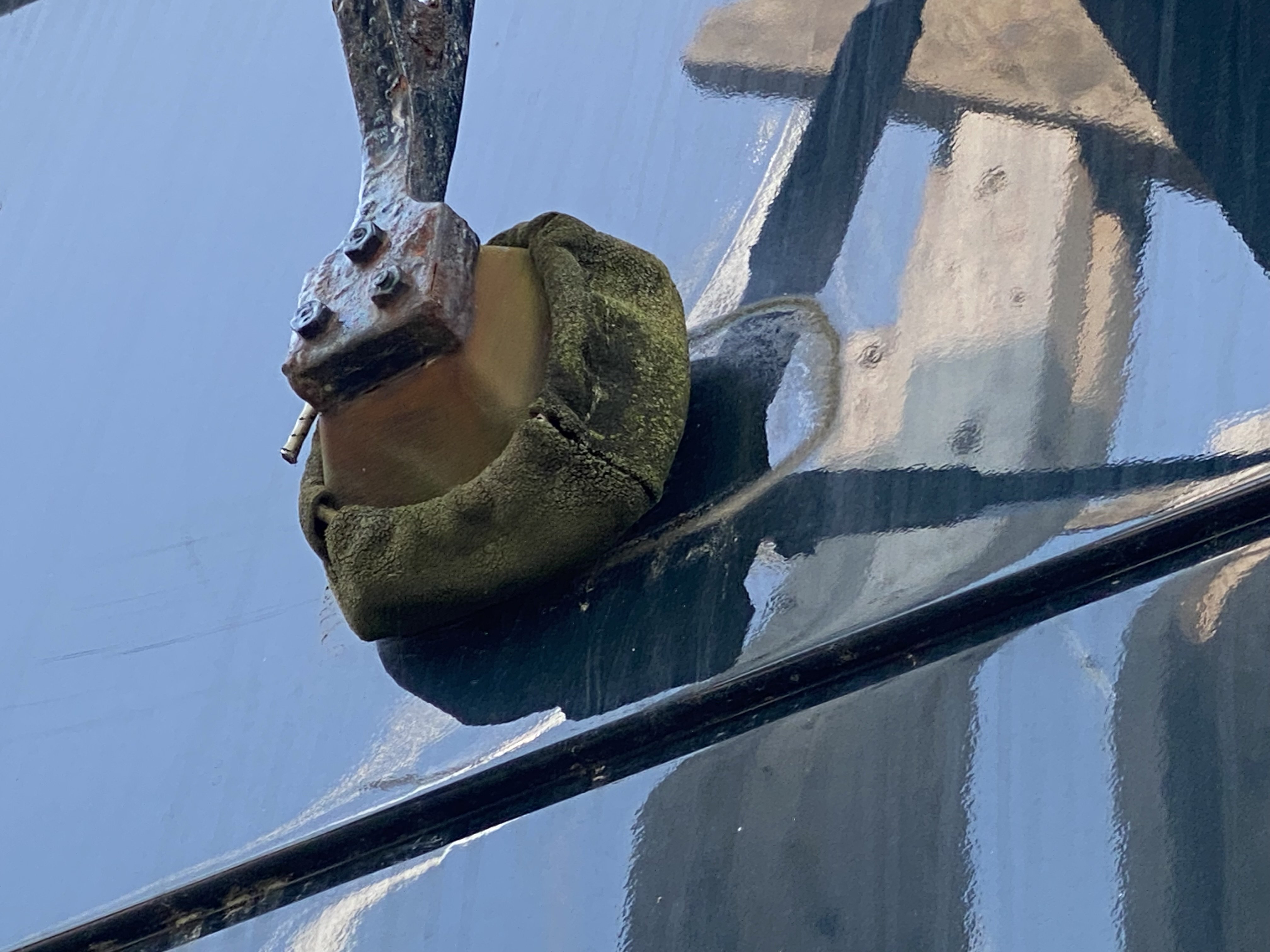
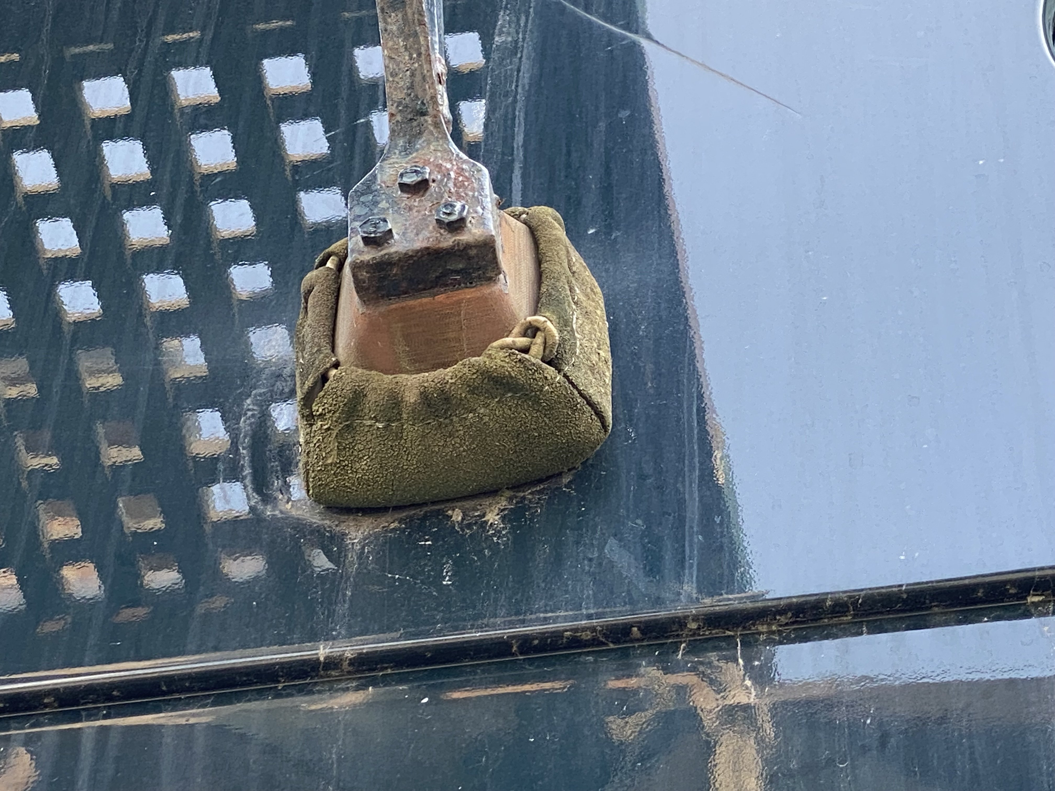
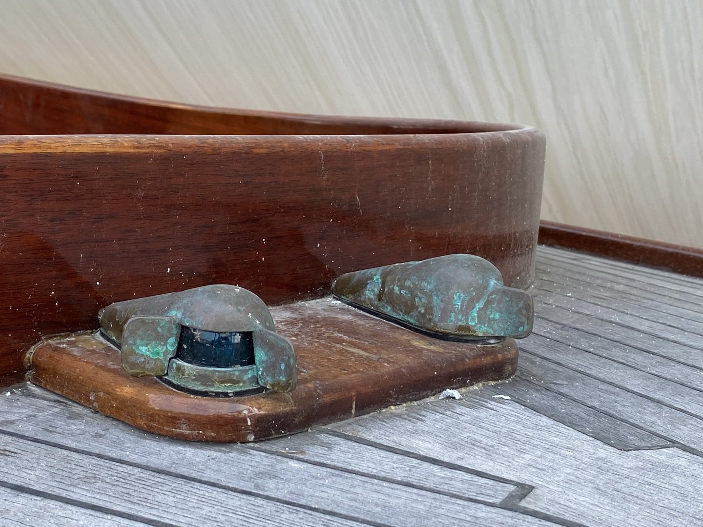
Rob , I agree with Rich that the ventilators in the planksheer would have some kind of valve(ball valve?) to prevent water from entering. The model of the clipper ship Challenge in the Smithsonian America History Museum has what appears to be a Ball valve on the end of the ventilator. I have an old photograph that I will try to find and post it. It’s a large model possibly 1:48 inches scale. I didn’t try to replicate it. Rick