HOLIDAY DONATION DRIVE - SUPPORT MSW - DO YOUR PART TO KEEP THIS GREAT FORUM GOING!
×


Richard44
-
Posts
429 -
Joined
-
Last visited
Content Type
Profiles
Forums
Gallery
Events
Everything posted by Richard44
-
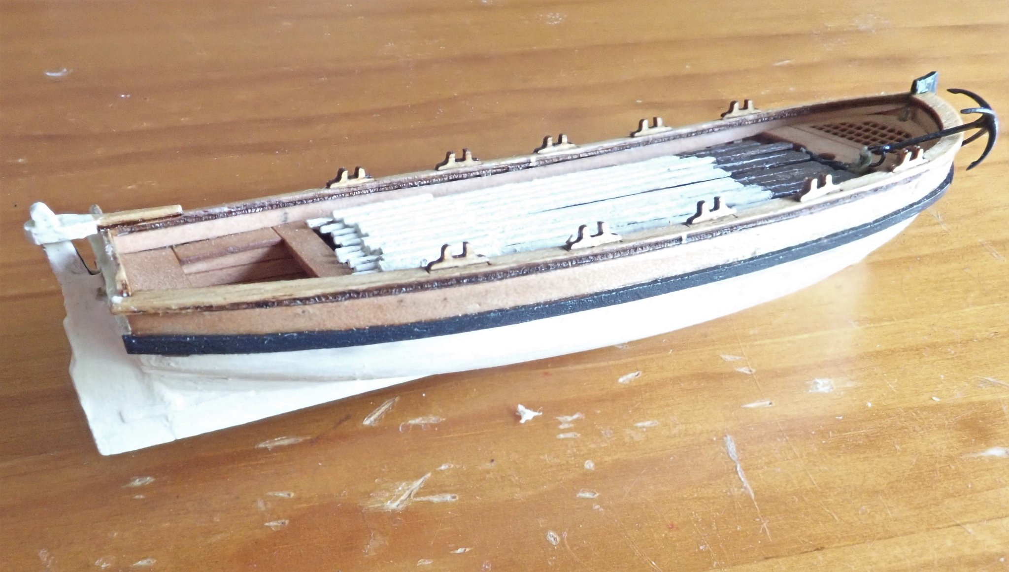
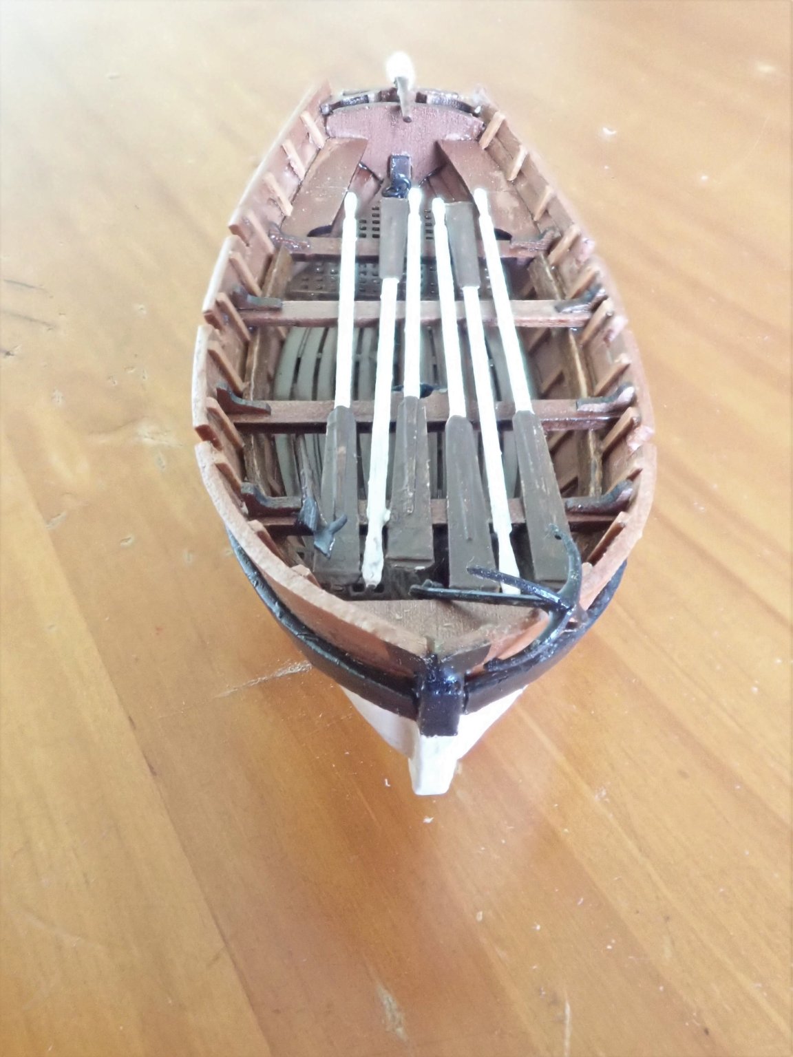
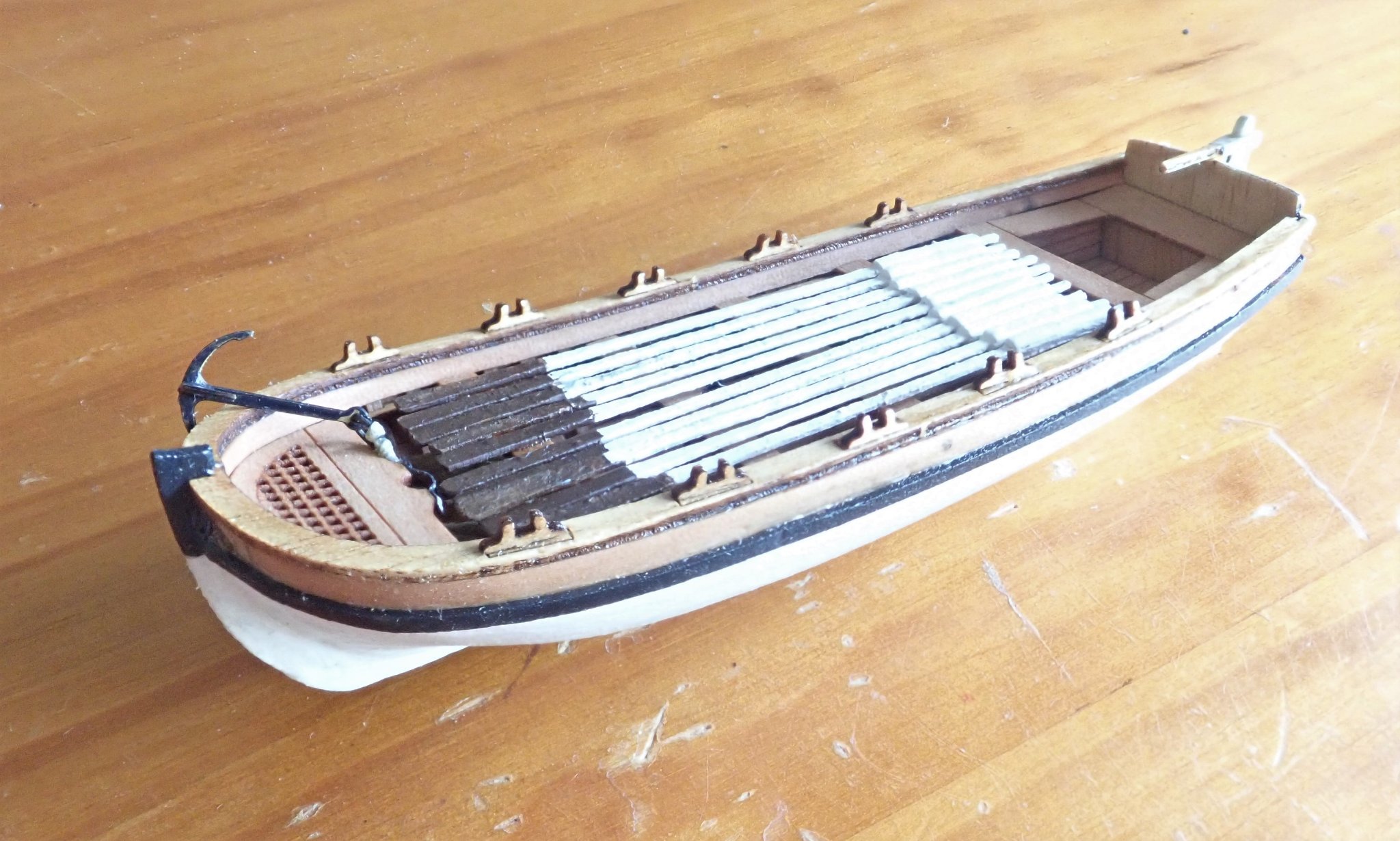
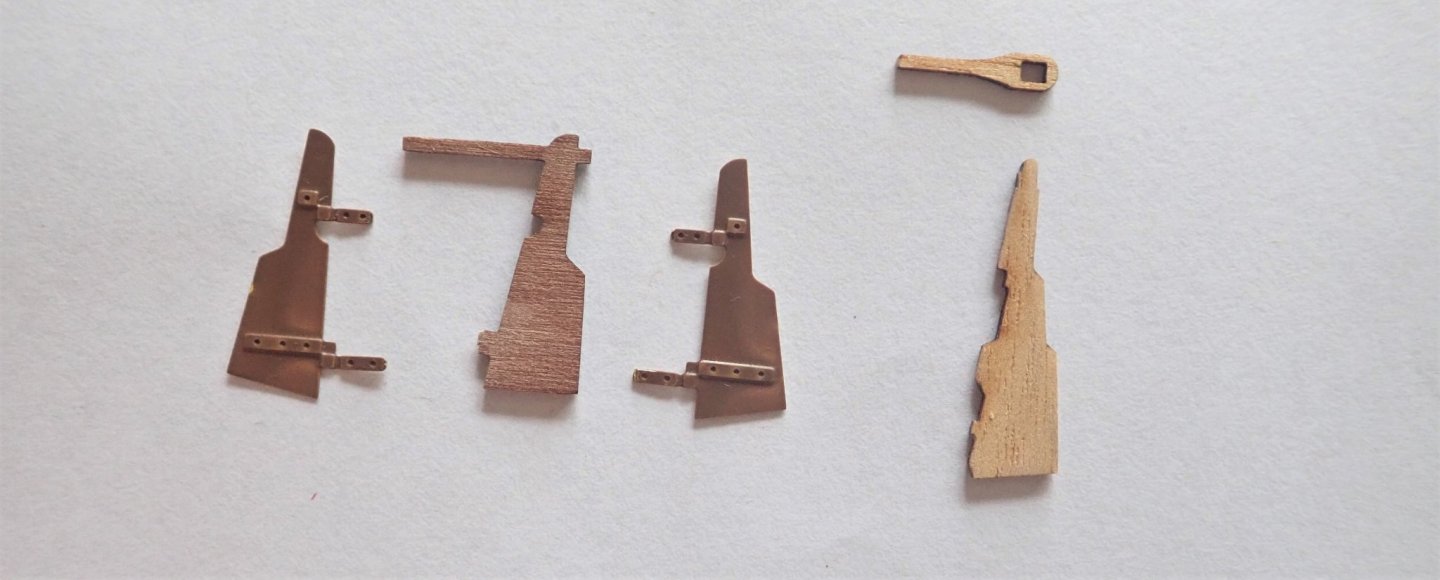
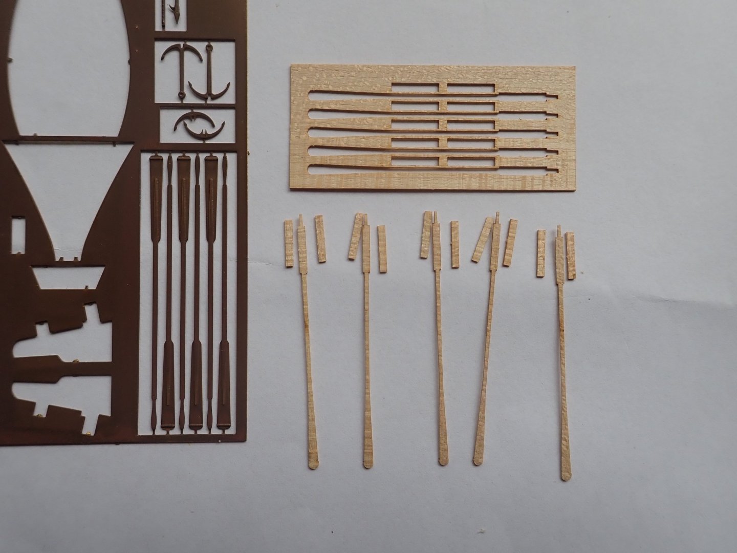
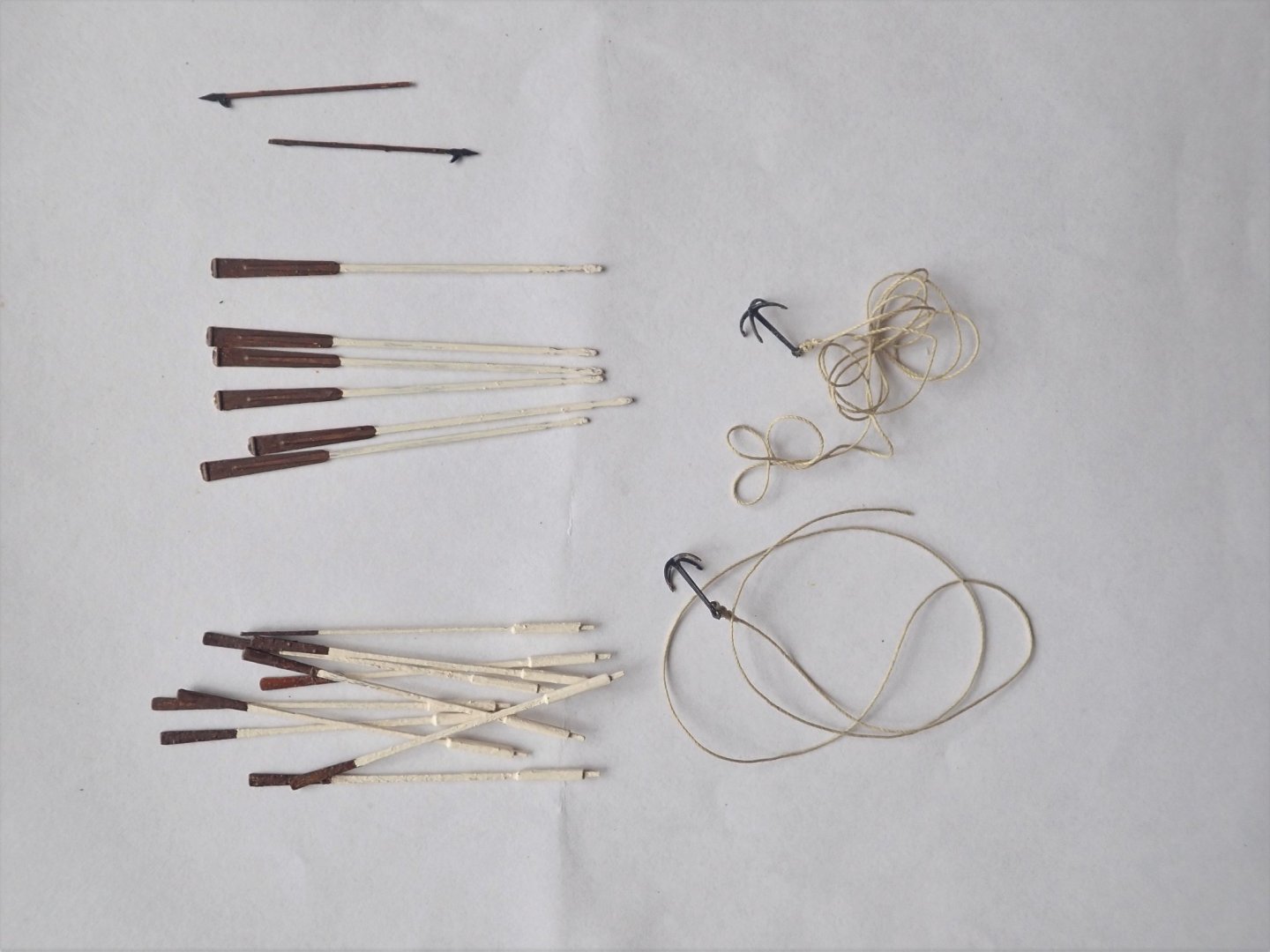
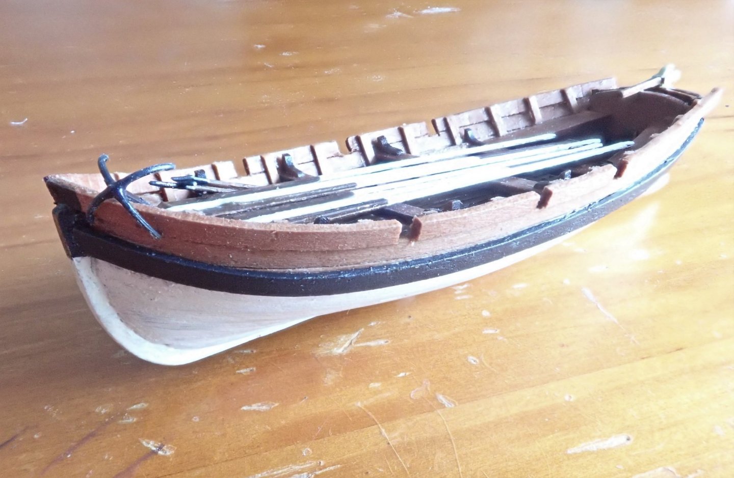
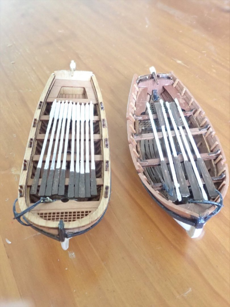
 Once all the ribs were in place in the VM boat, the gunnel was glued in position. The ribs were then trimmed flush with the top of the gunnel. The small slots in the gunnels for the oars, three each side, were carefully cut using a standard razor saw, albeit one with 54tpi. The MK boat has thole blocks (I guess they’re called) on top of the gunnels for the oars. Both boats were then just about complete, but both lacked rudders. The VM kit comes with a wood core (rudder plus tiller) and PE facings to go on each side. The facings have the pintles and gudgeons as shown. For some reason I didn’t particularly like this setup, so I just used the wood core. The MK kit just has separate rudder and tiller, both wood. I now had to make the pintles and gudgeons for both boats, but after several attempts I decided that my skills were not sufficient to make such tiny parts. I therefore glued, using epoxy, the rudders to each boat, and used narrow paper strips to represent the braces for the pintles and gudgeons. The Vanguard boat complete with rudder and tiller. The Master Korabel boat complete with rudder and tiller. The oars for the VM boat were PE, and only needed painting. The MK kit supplied very delicate laser-cut wooden oars that needed the handles built up and rounded off. These had a rounded end which I squared up. They too were painted. Vanguard supplied two PE grapnel-type anchors, shown in the above photo. These were assembled (only two parts each), rings added to the shanks and rope tied to the rings (neither were supplied). I decided to put one anchor in each boat. The painted oars, assembled anchors and boat hooks. Black painted planks were glued below the gunnels to be the wales. Finally the bottoms of the boats were painted white, the topsides and interiors left natural. The Vanguard boat. The Master Korabel boat. Both kits were tricky to build. Vanguard have now released an updated cutter kit, so while I have a few niggles about my kit, they’re irrelevant now. The Master Korabel kit had superb laser cutting that needed almost no sanding to get pieces to fit. The instructions though needed some interpretation, but otherwise were perfectly adequate. Cheers.


- 6 replies
-
- 2
-

-
- master korabel
- Finished
- (and 2 more)
-
That's a good looking capstan Tim, and very well done with the pumps.
- 164 replies
-
- 1
-

-
- fly
- Victory Models
- (and 4 more)
-
Nice work Eugenio, your latterns look really good, as does the stern. I agree about the chains, they do look oversize. Cheers
-
I had the same trouble with my older cutter kit - I think I also used strips of masking tape wound around the hull. Great fun 🙂.
- 70 replies
-
- 3
-
-
- 22ft Yawl
- Vanguard Models
- (and 2 more)
-
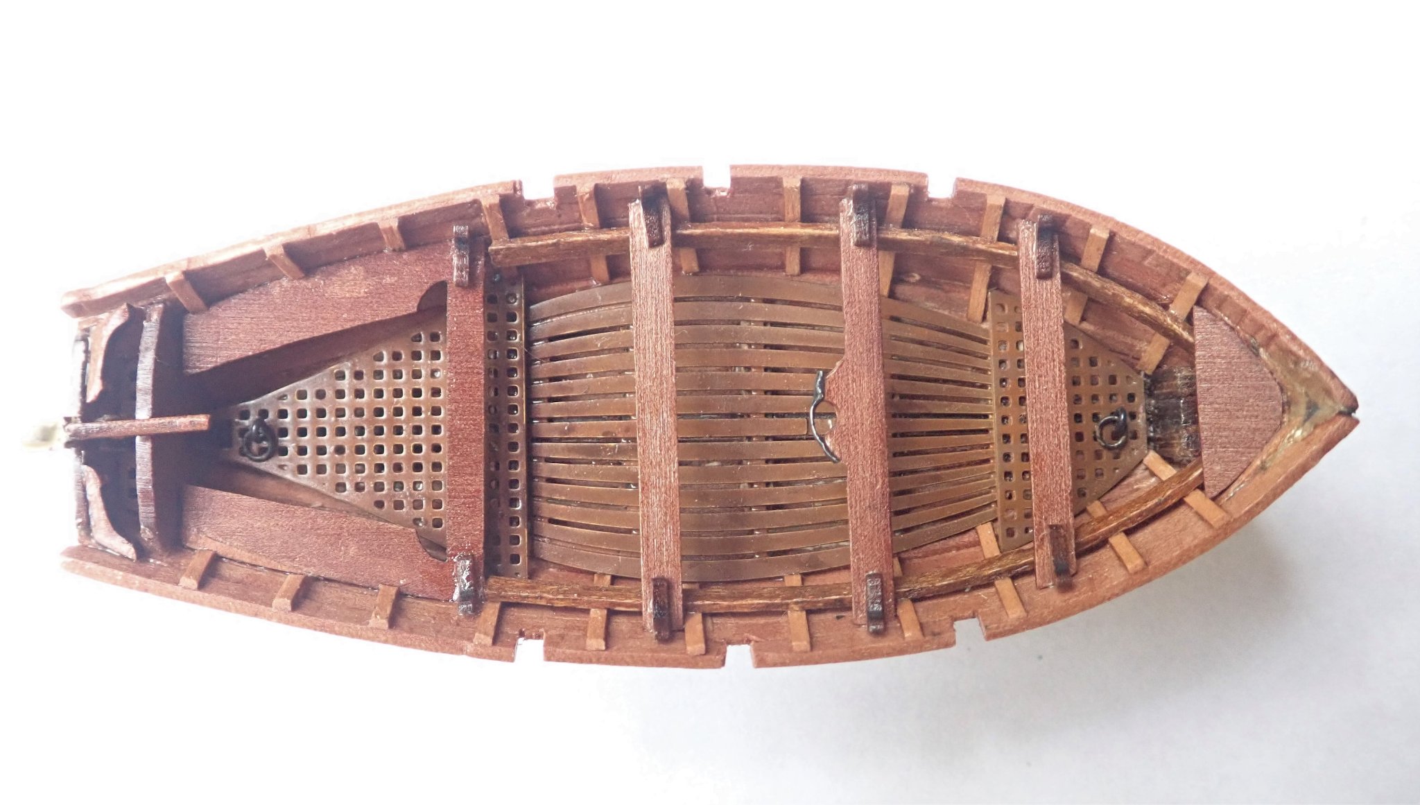
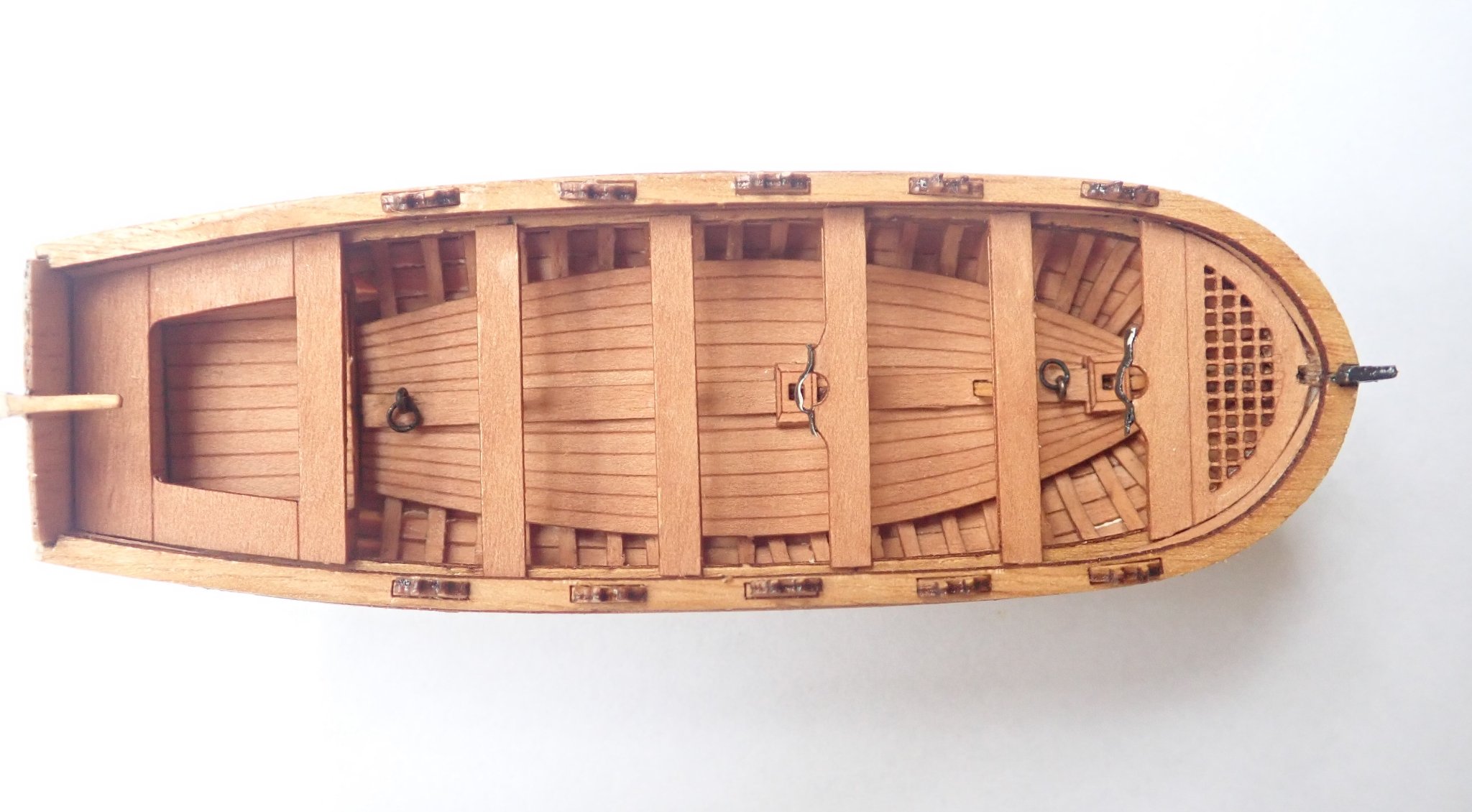
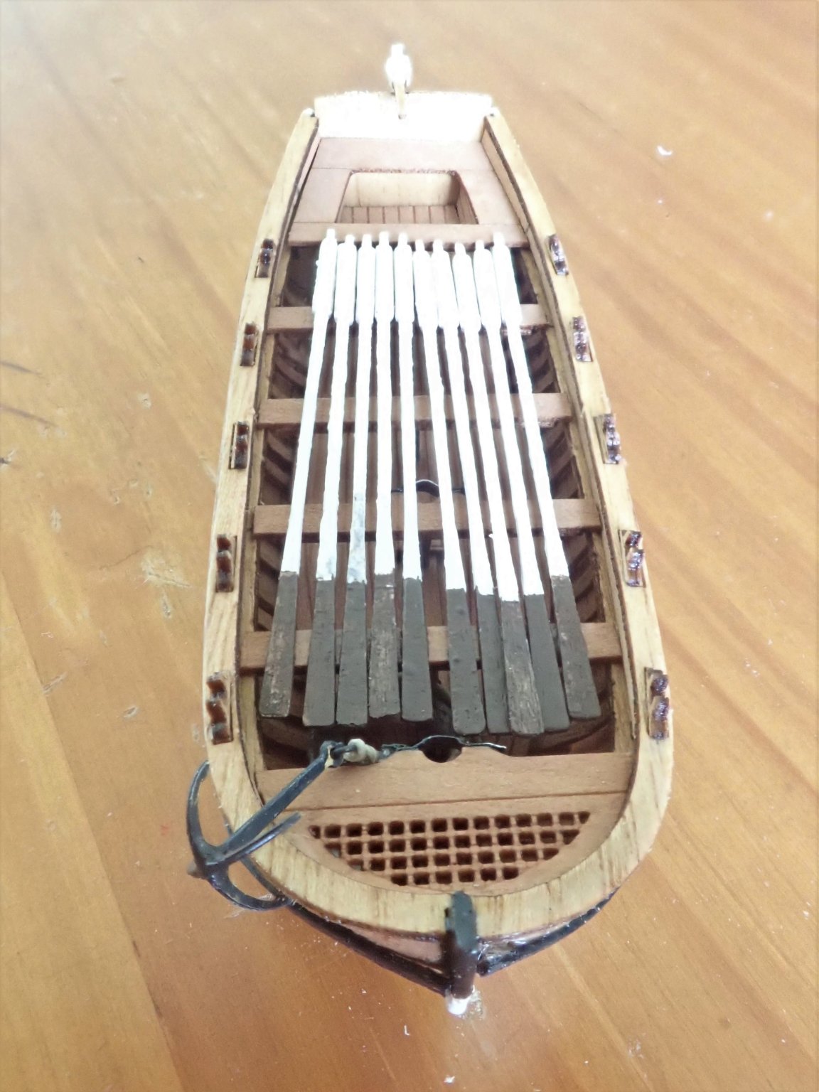
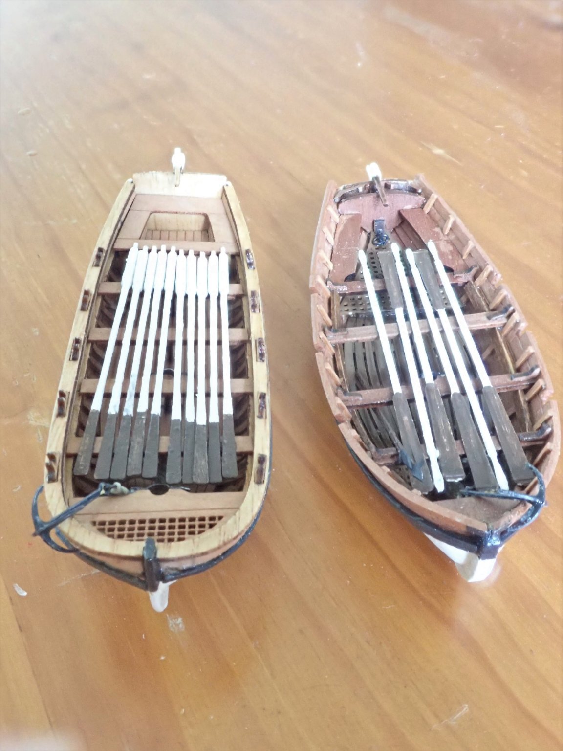
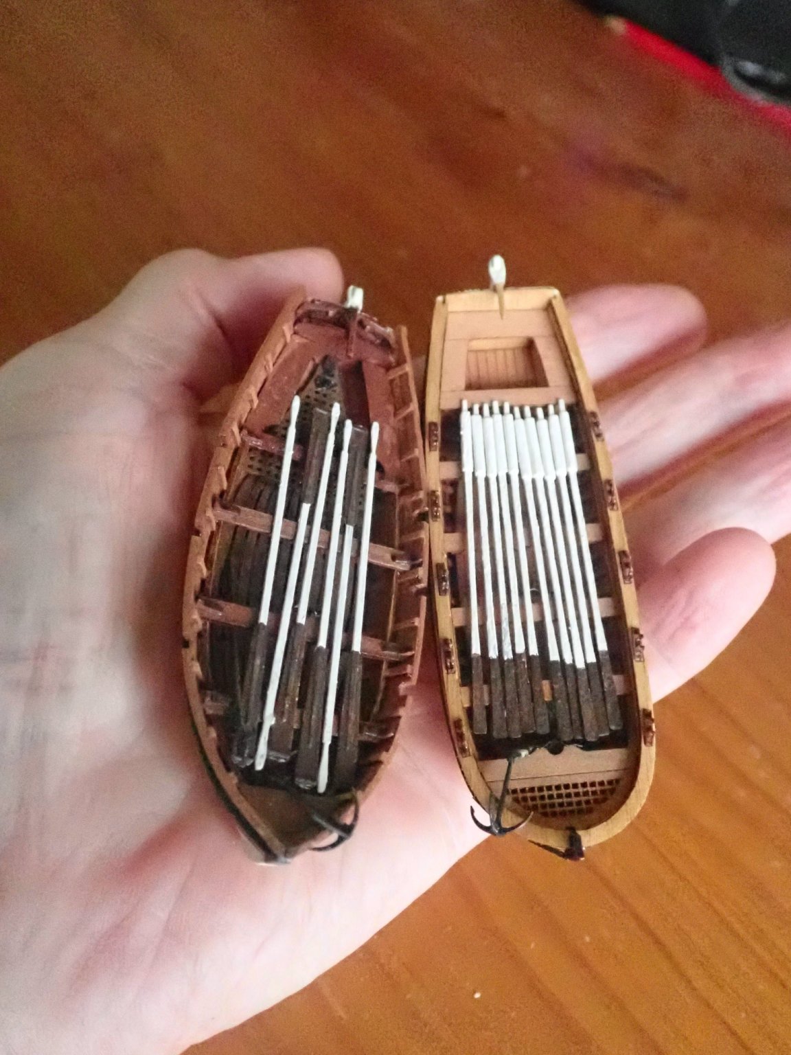
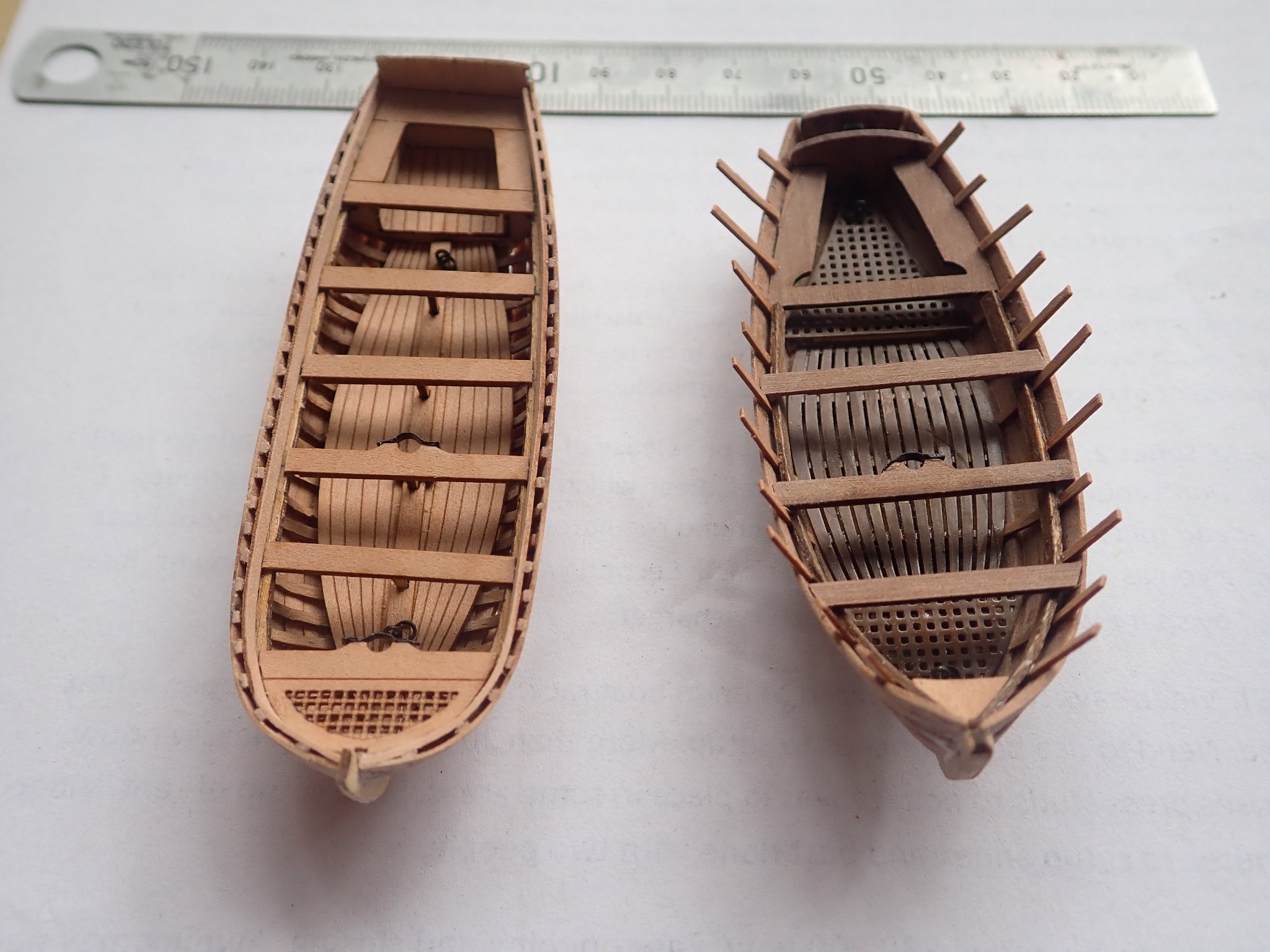
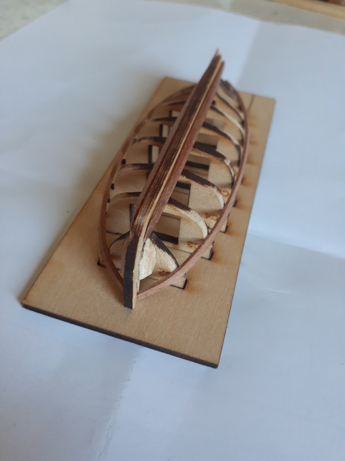
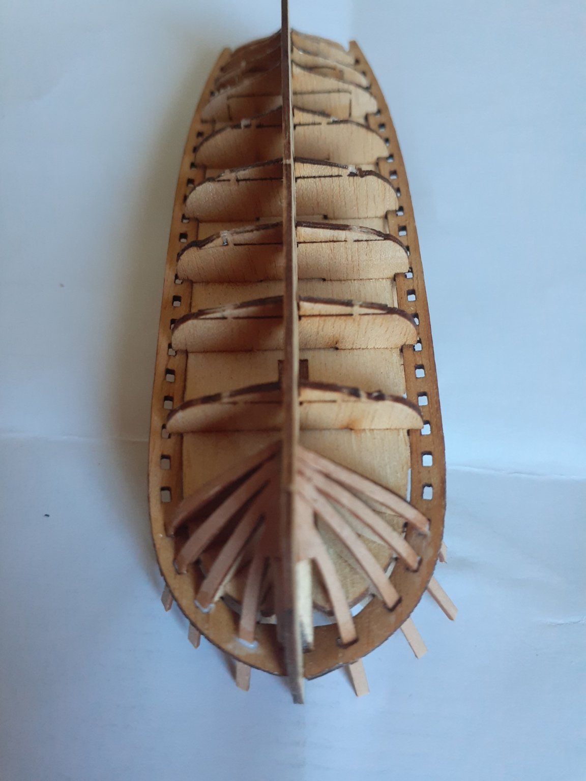
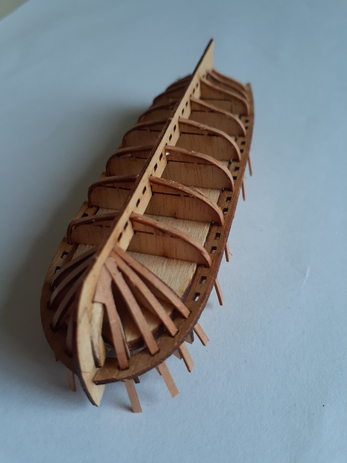
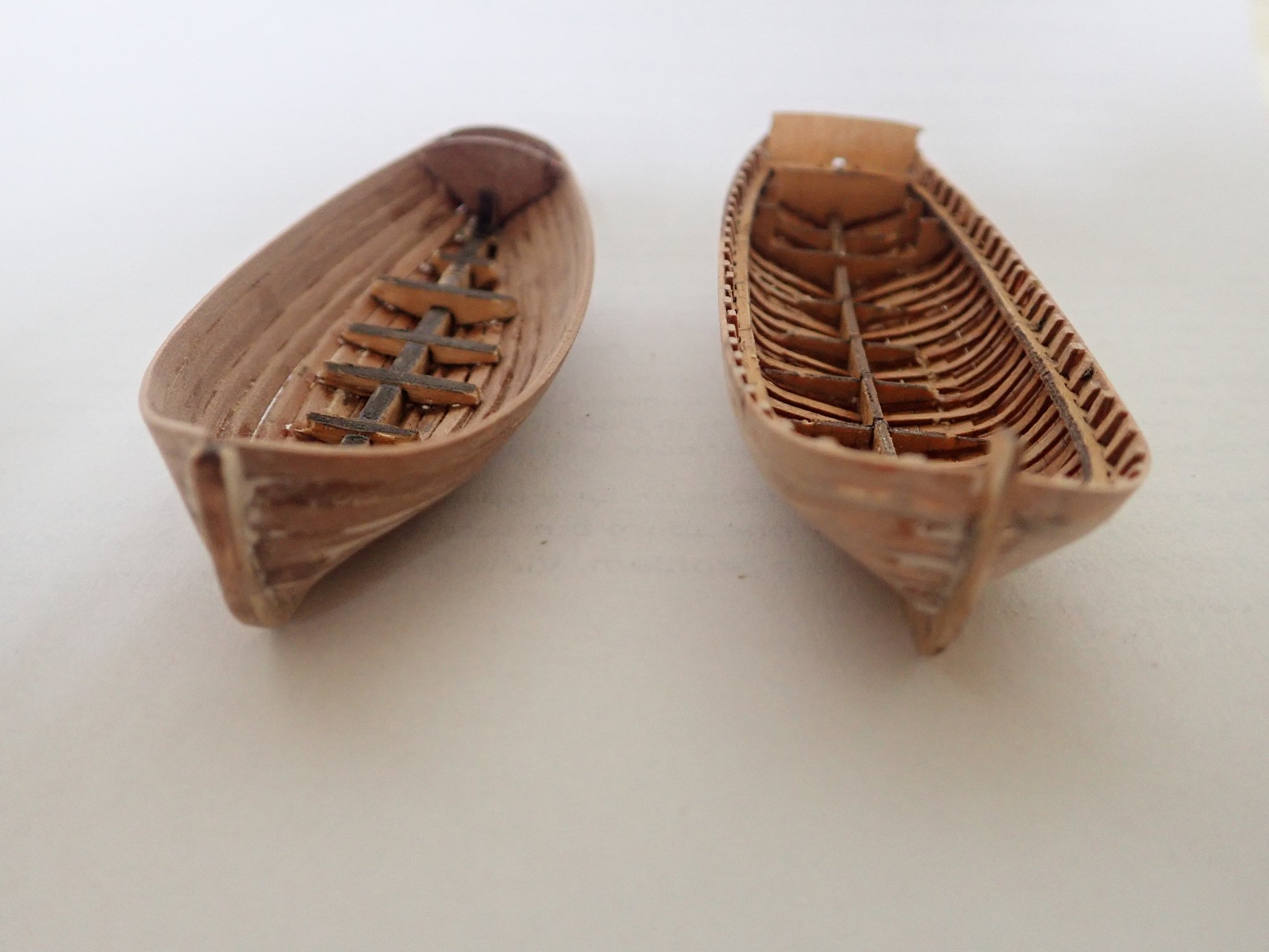
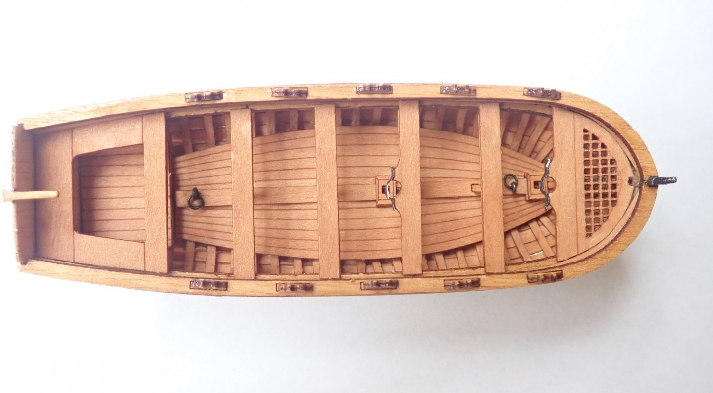
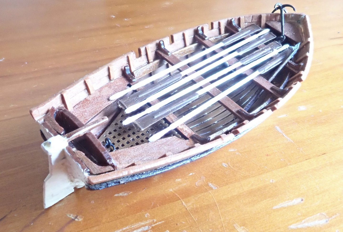
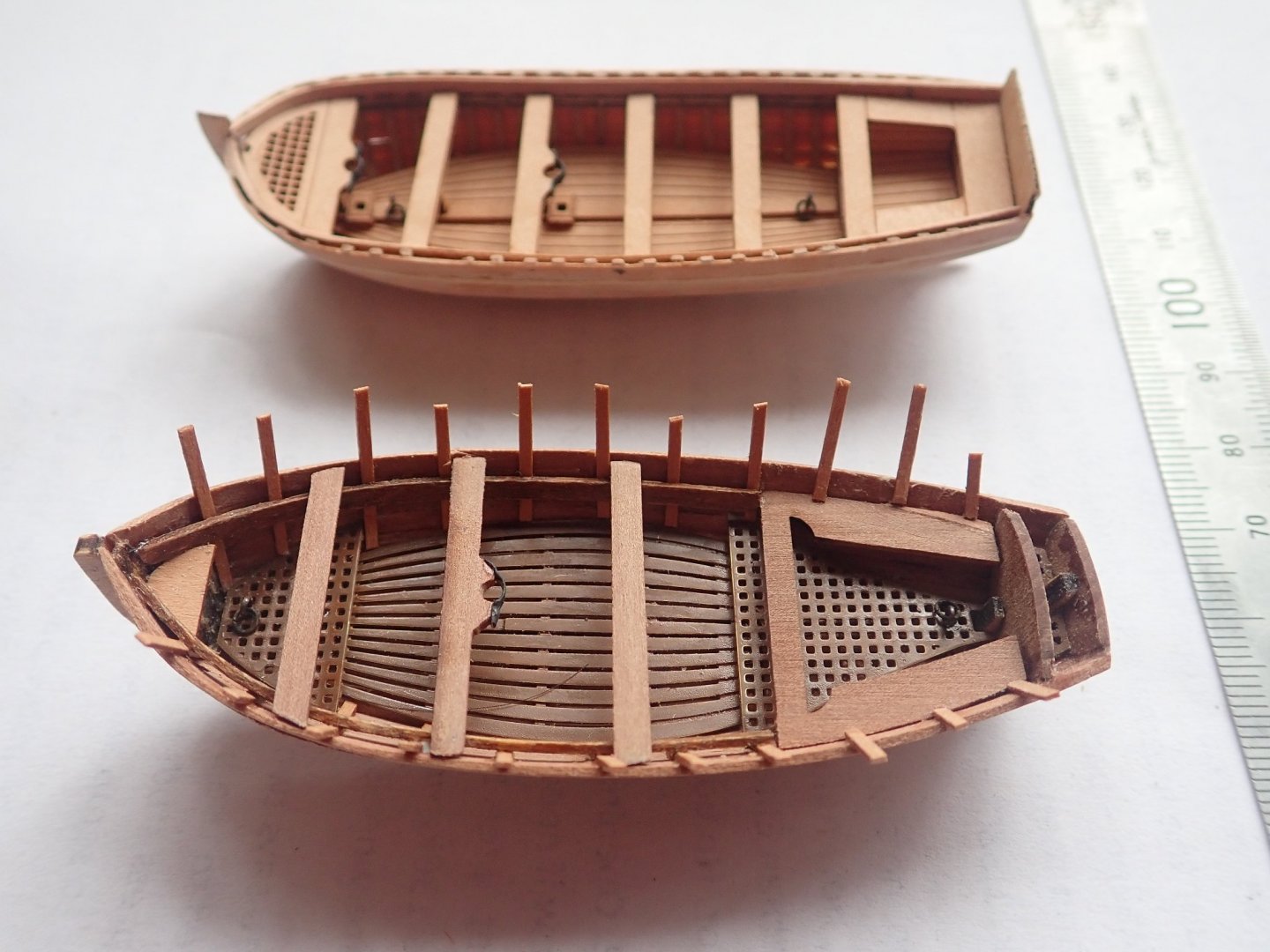
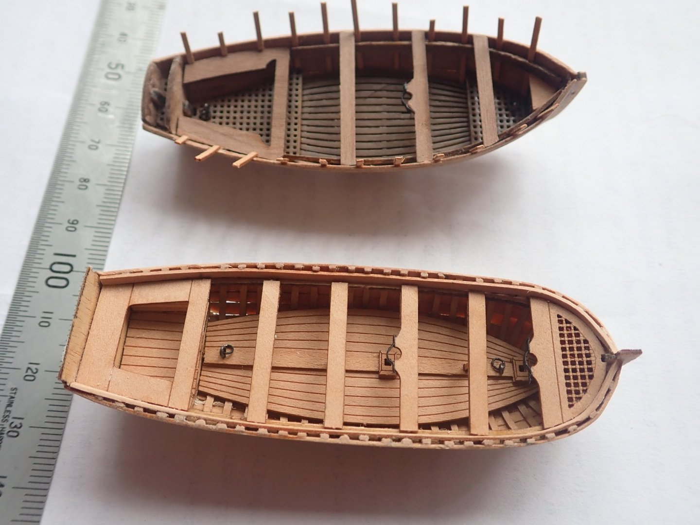
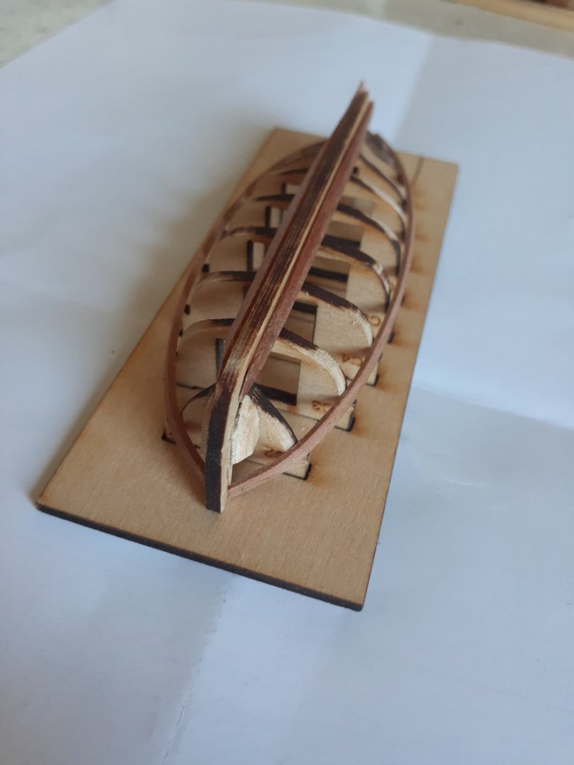
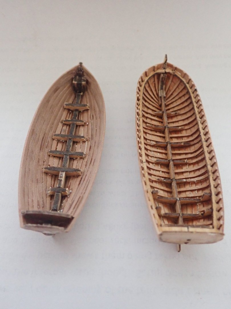
Work on the boats has continued, albeit slowly. The following photos show them after finishing most of the interior fittings. The VM boat uses PE for the floorboards and gratings whereas those in the MK boat are laser cut and scribed. The ribs for the VM were made from leftover 0.6x1mm pear strips from the MK kit, rather than trying to cut down the 1x2mm strips as supplied (the new cutter kit does provide 0.6mm pear for this purpose). The ribs in the VM boat have not yet been trimmed. The instructions say to trim these level with the top of the planking, which makes gluing the gunnel on top of the planks awkward as there is little or no support (as B.E. has pointed out in his log). A photo of the new cutter shows the ribs extending above the planking in order to support the gunnel and I have kept the ribs overlong at this stage in order to do this. I have added lifting ringbolts in both boats and a small foredeck in the VM boat to cover the ply stem. Cheers

- 6 replies
-
- 3
-
-
- master korabel
- Finished
- (and 2 more)
-
Thanks for the comments guys. I've been following both of your logs with much interest. My progress has been slow recently, but I hope to have an update soonish. Cheers
- 104 replies
-
- 1
-
-
- pegasus
- victory models
- (and 2 more)
-
That's looking really good Tim, you're way ahead of me 🙂. Cheers
- 164 replies
-
- 1
-
-
- fly
- Victory Models
- (and 4 more)
-
Hi B.E. Your boat is looking really good. I'll have an update on my build soon. Like you though, the stern sheets didn't quite fit my hull, and I'm now trying to correct for this. About the rudder. The rudder/tiller is one piece and when I did a dry fit of it against the hull I found that the tiller does not quite clear the transom. The easy solution of course is to round down the transom. In the photo, your new rudder looks taller than the original. I don't yet know though whether I'll modify/re-do the rudder similarly to what you're doing. I'll complete my build and log even though the kit has been superseded. Cheers
- 70 replies
-
- 1
-
-
- 22ft Yawl
- Vanguard Models
- (and 2 more)
-
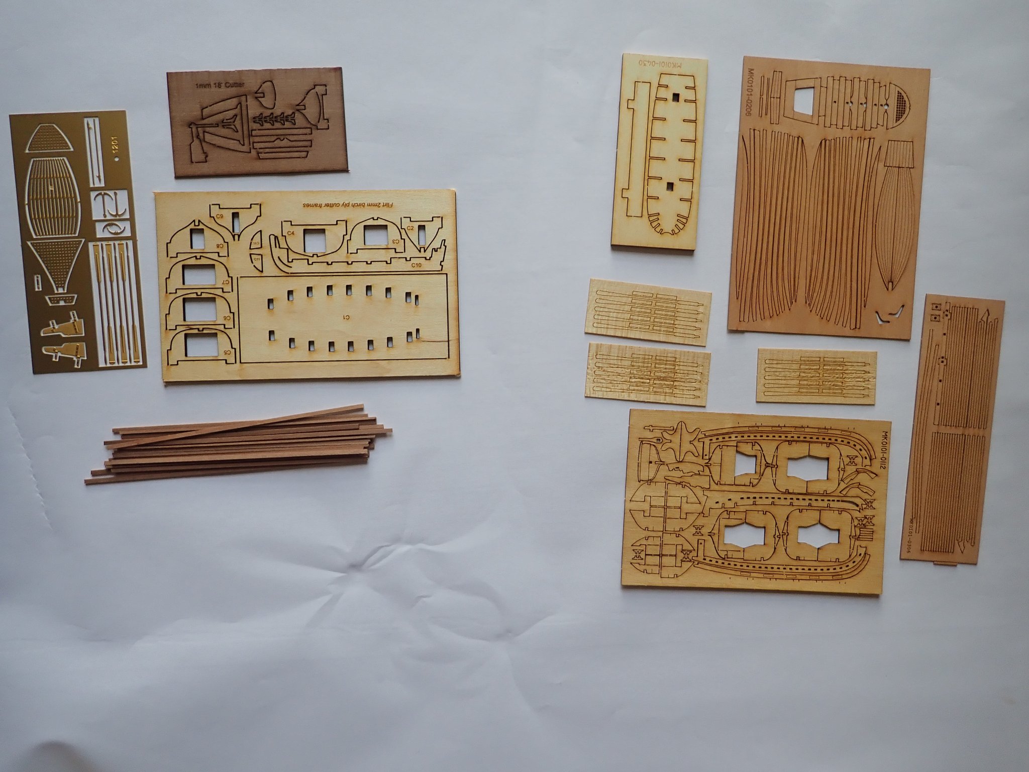
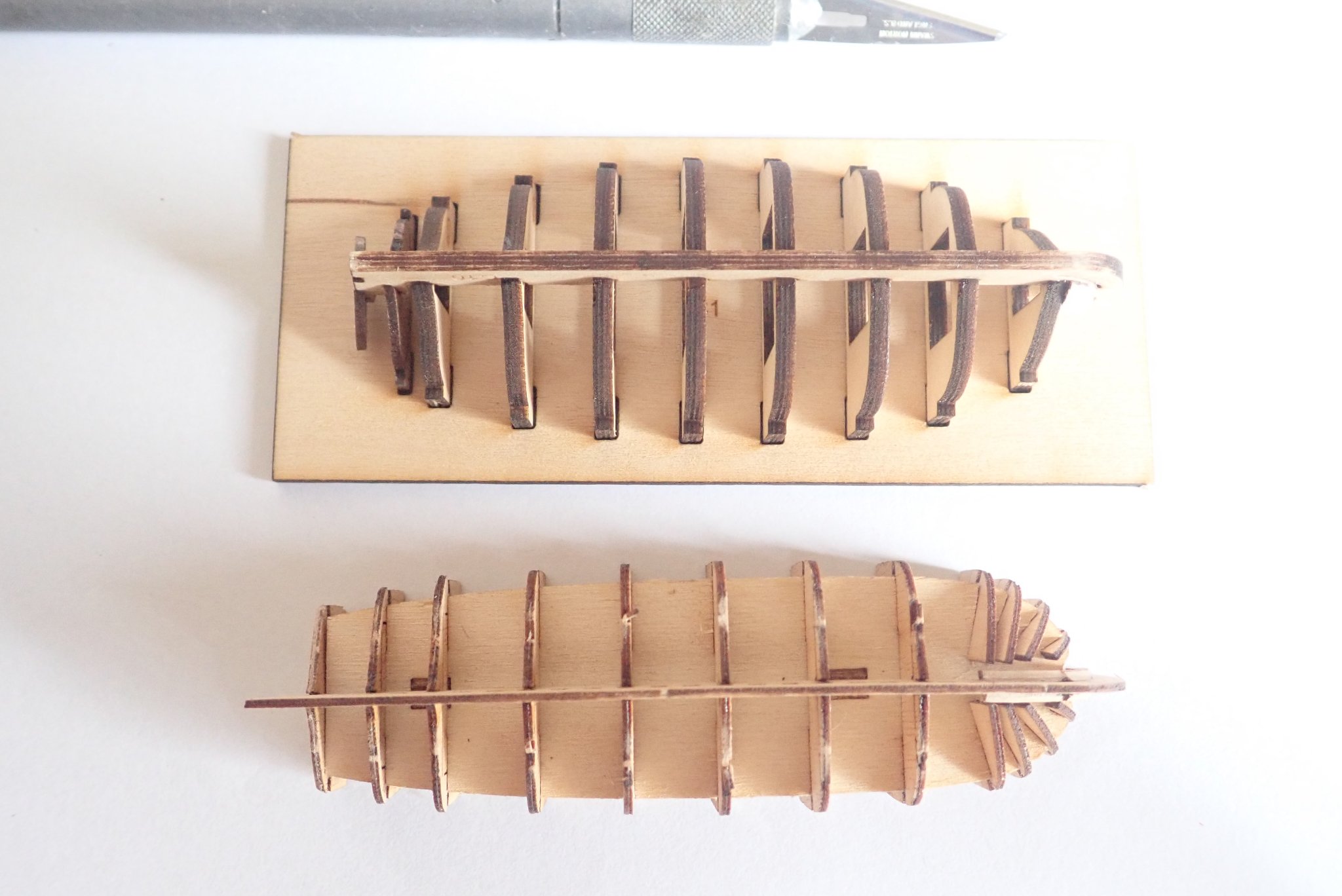
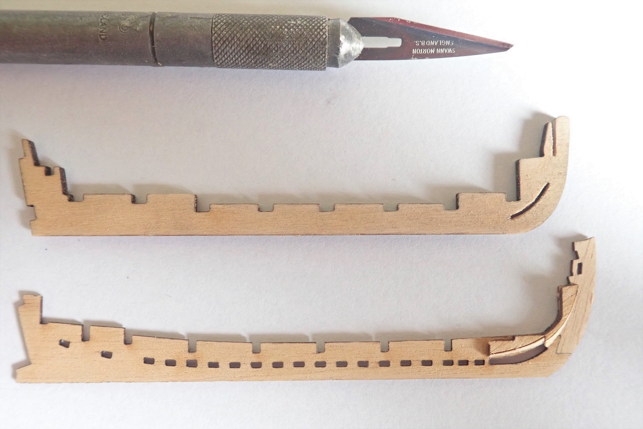
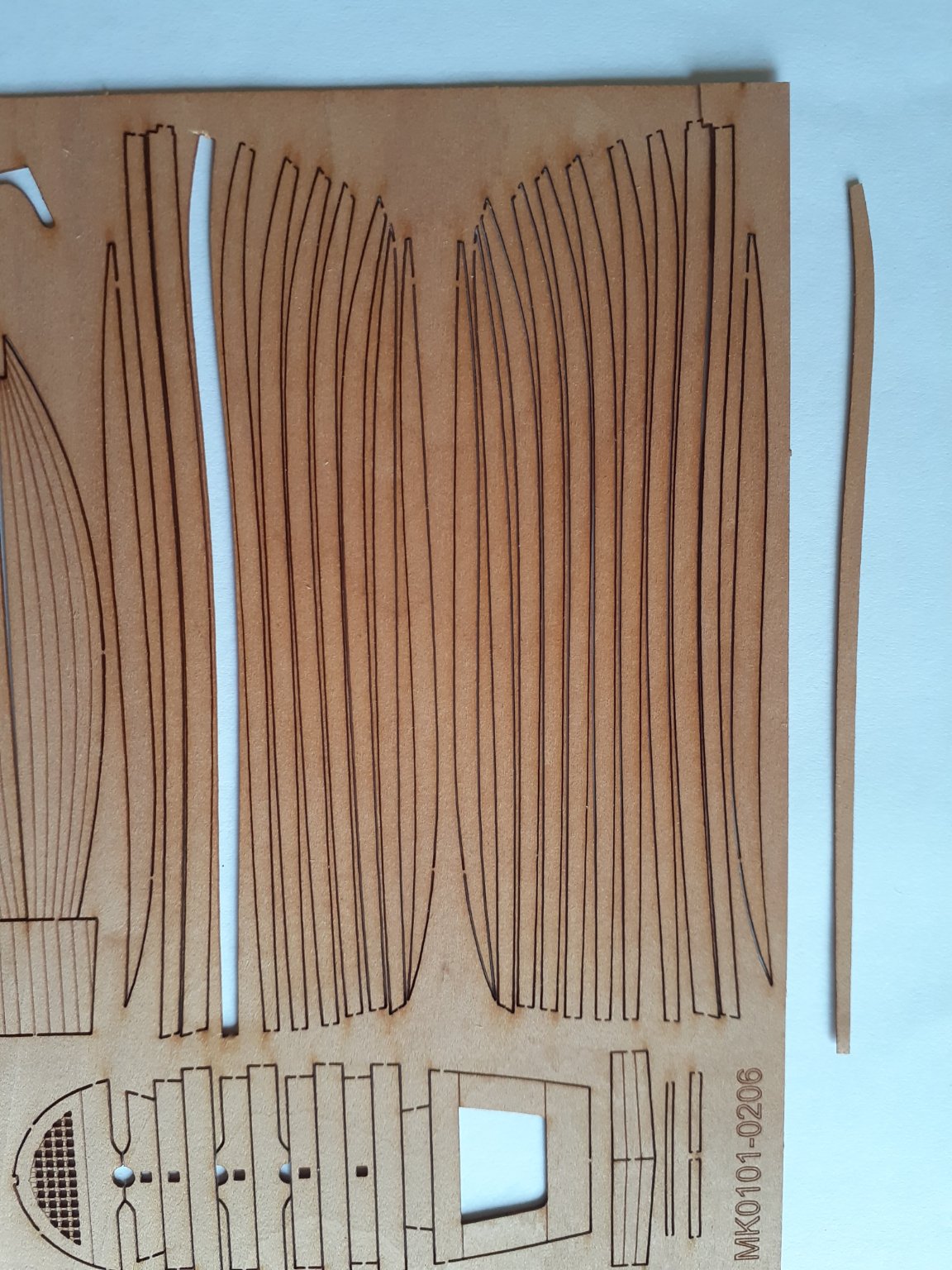
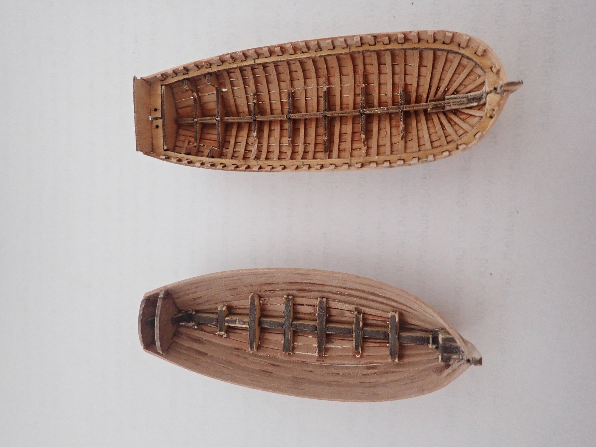
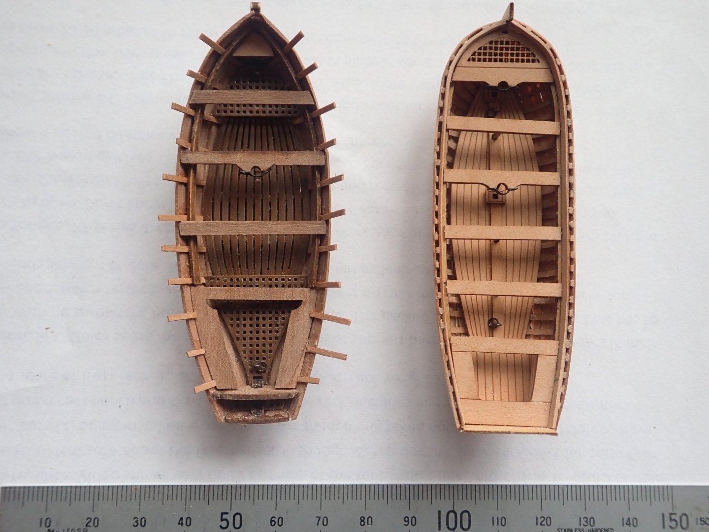
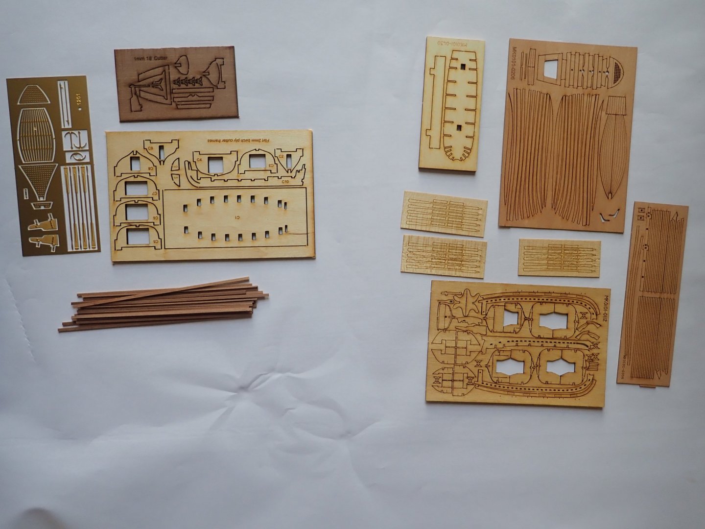
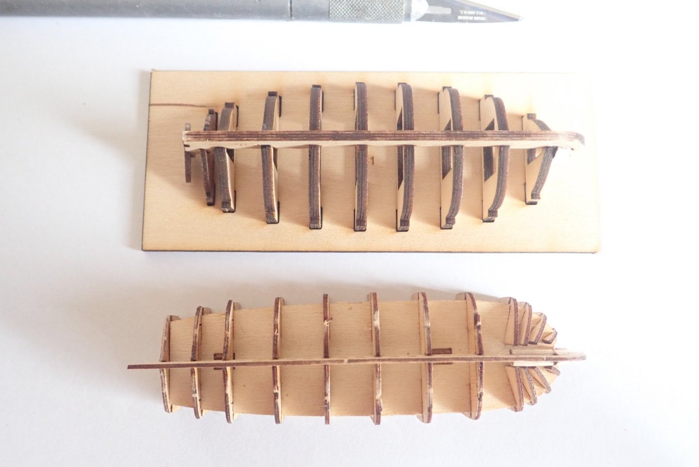
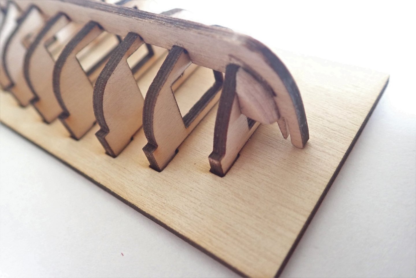
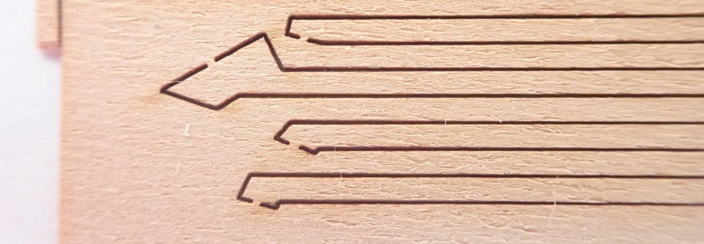
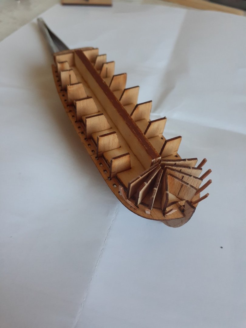
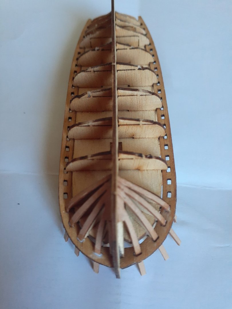
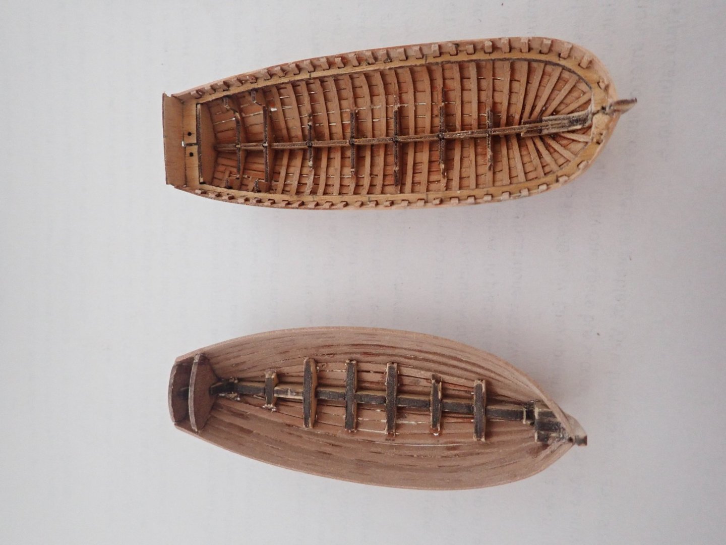
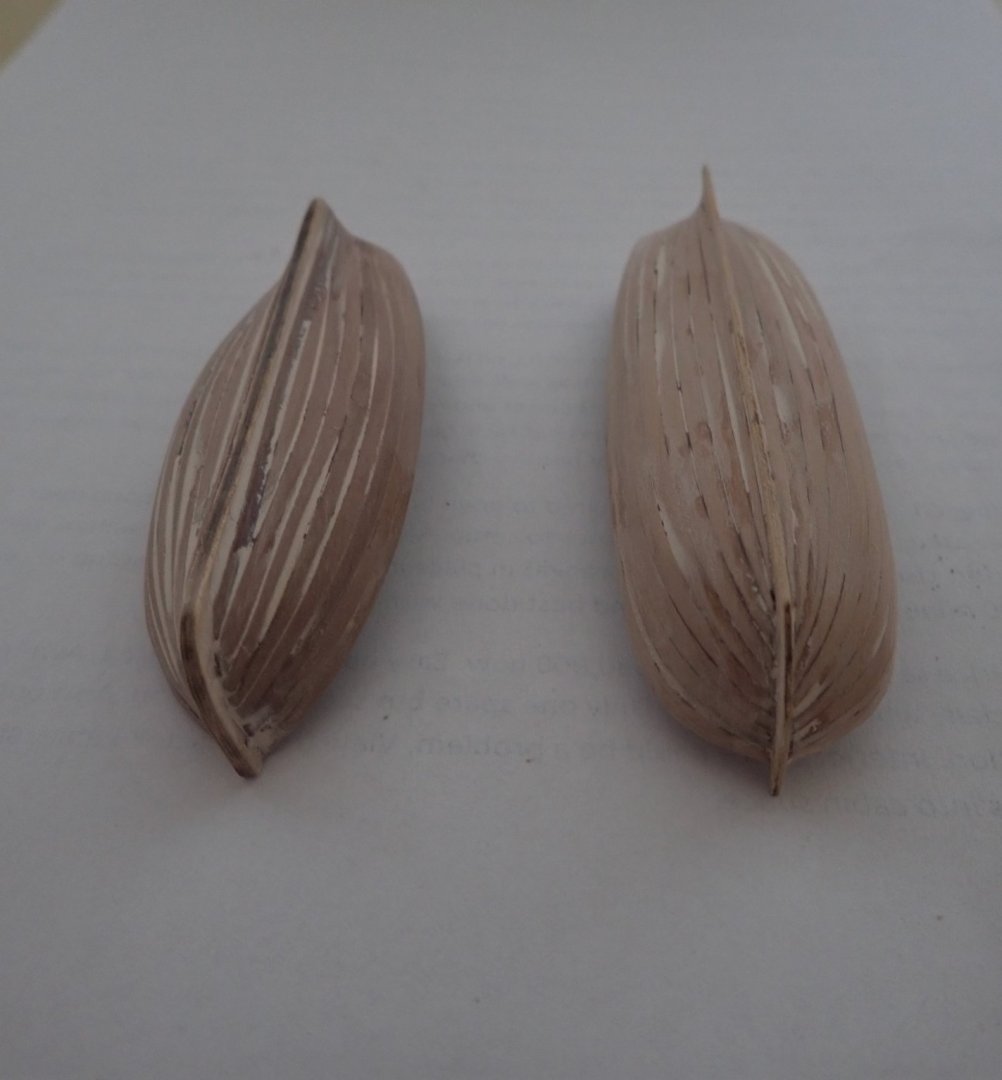
Many months ago, I ordered the Master Korabel (MK) kit, but pandemic struck and delivery was delayed. Meanwhile, Chris (Vanguard Models, VM) released his cutter as a standalone kit, so I also ordered this. Both kits arrived within a week or so of each other, so I thought that I would do a comparison build log rather than two separate logs. The log lacks a little as I somehow managed to lose some photos and couldn’t recover them. Although the VM model is to a scale of 1:64 while the MK one is 1:72, I think they are close enough to stand comparisons. I have put this build log into the 1751-1800 time slot, as is my Pegasus build, though the boats could easily belong to other periods. The two kits. The VM is on the left and has two laser cut sheets, a sheet of PE and a bundle of 1x2mm pearwood strips. Instructions need to be downloaded from the VM website. When the kit contents are compared to the instructions, it seems that something is missing. There are only 1x2mm strips in the kit yet the instructions mention 1x3mm strips in a few places. I checked this with Chris and he told me that he re-considered the 1x3mm strips as he thought that they were over-scale and replaced them with 1x2mm. The MK kit contains only seven laser cut sheets of various thicknesses - no PE. Instructions are included - a sheet of photos at various construction stages, a sheet showing all the laser cut pieces with each identified, and a double sided sheet of written instructions in English, though the terminology takes a bit of getting used to. Both kits start out the same - make up the jigs which are used until planking is complete. The keels with the VM one on top. The MK one has small slots along it through which ribs are inserted, and has small fairing blocks glued at the stem. These have laser etch marks to show how much bevelling is required before gluing in place. The two jigs, the VM one on the top. Formers are glued to the keel, and the formers in both kits are partly cut to allow removal from the shell of the boat once planking is finished. Fairing blocks are in place at the stem of the VM model. The VM kit is relatively simple, and planking starts immediately. I started by gluing in place the garboard strake, then continued as per the instructions. Tapering of the strips is required, I did this by eye, and finished up by only needing one stealer strip next to the garboard strake. The MK kit requires you to glue ribs in place first, with the first four at the bow being pre-cut to allow them to fit together. The first four glued in place. There is a horizontal former (I guess you’d call it) slotted to let the ribs be fed through it, then through the keel slots and back up the other side. A few minutes soaking allowed this to happen relatively easily. With care no breakages should occur. The next set of ribs are positioned over the formers glued to the keel, and can be carefully glued to the very bottom of the formers, but not the tops. The dark lines on the formers show where they will be broken to allow the tops to be removed later Once those ribs are in place, planking starts. All the planks in the MK kit are laser cut and spiled. Once planking is complete, the shells are carefully removed from the jigs and the formers broken away. At this time the remainder of the ribs in the MK kit are fitted. MK boat on the top. VM's cutter on the left and the MK boat on the right. As I intend to paint both boats, putty was liberally applied to the hulls to cover the places where adjacent planks didn’t quite meet (ie the gaps). The VM boat is on the left. Next will be the interiors. Cheers.


- 6 replies
-
- 6
-
-
- master korabel
- Finished
- (and 2 more)
-
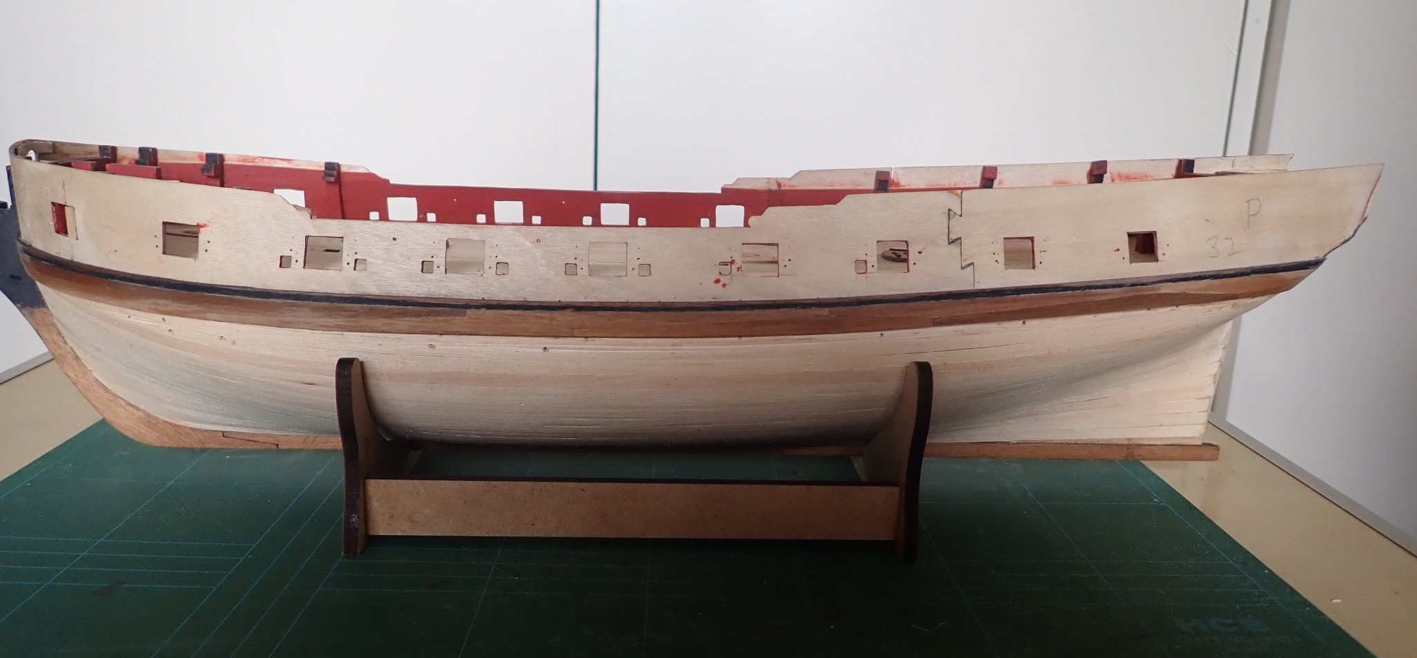
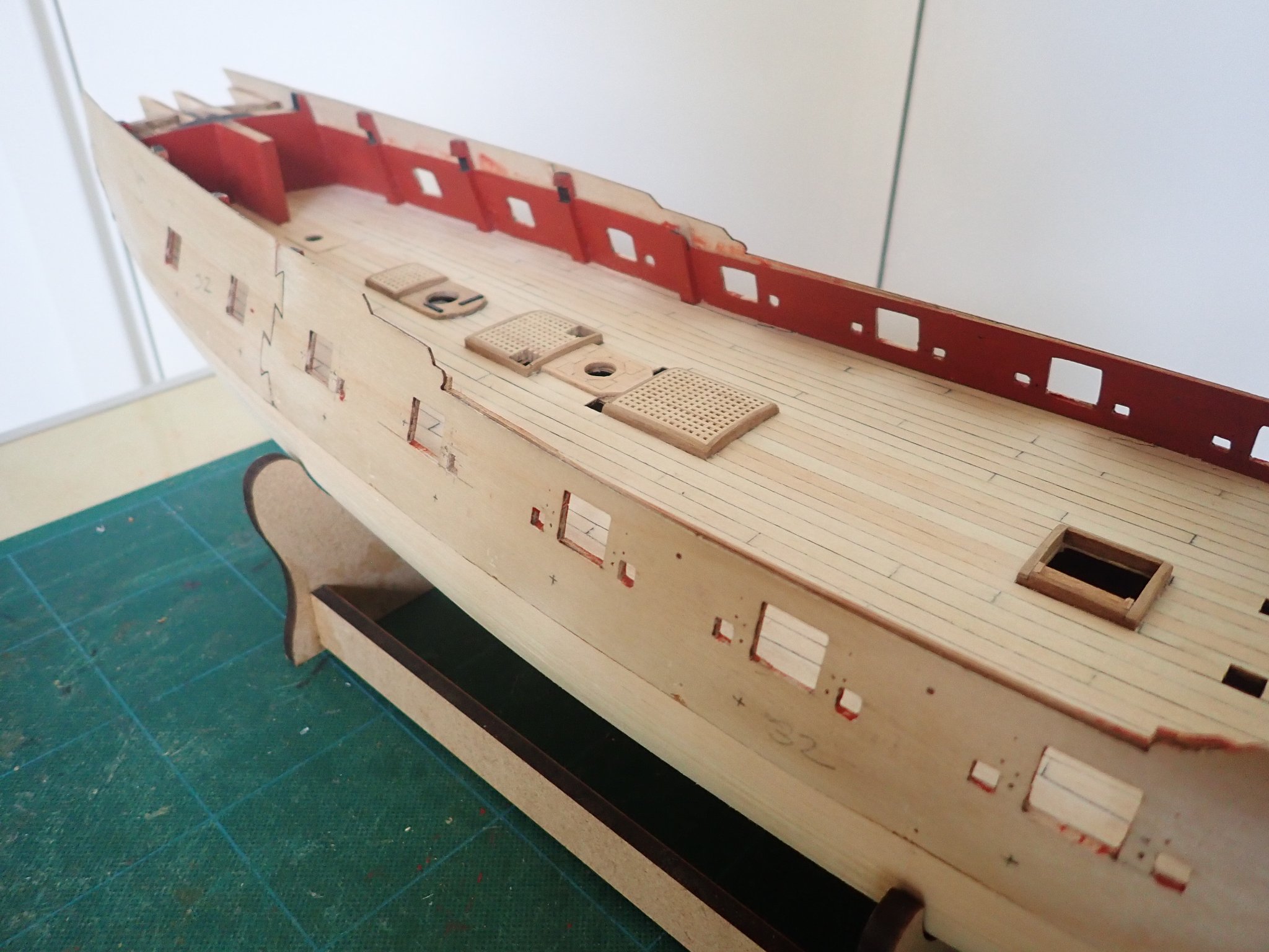
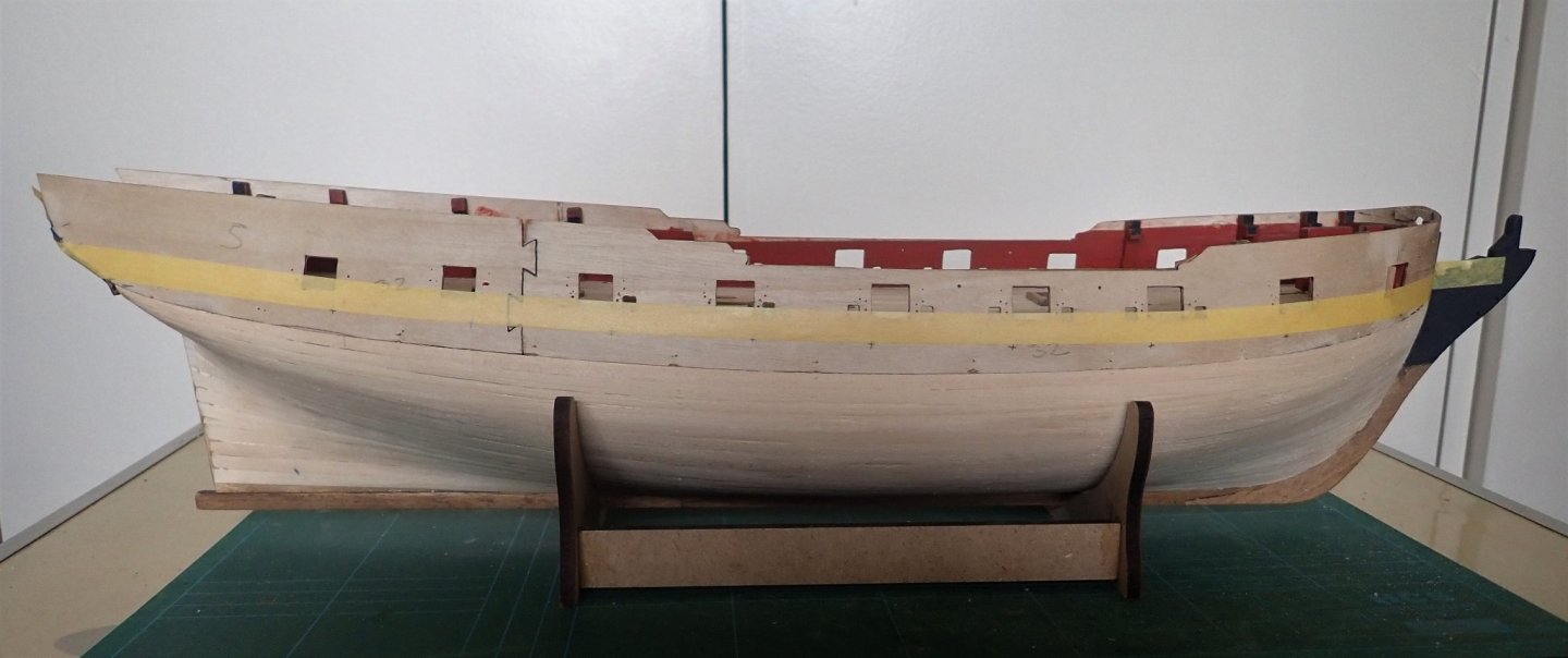
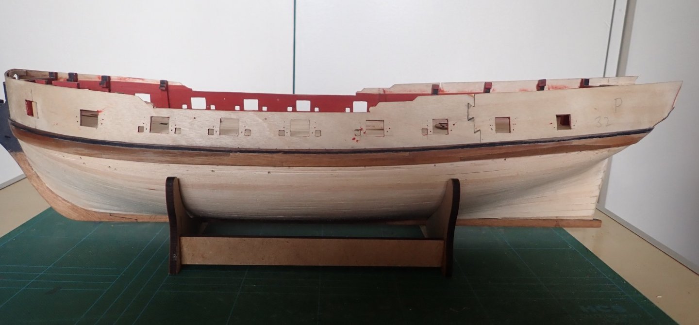
Just a short update. The second planking above the wale has at last been completed. With the wale in position, I measured from its top edge up to the top of the gunport pattern amidships. This was exactly 24mm, and given that the supplied wood for the second planking was supposedly 4mm wide, I thought six planks will neatly go here. However, after five strakes it was obvious that the last 4mm strake was going to be far too wide. I guess I should have measured the supplied wood, but I didn’t think of it. The wood is actually 4.2mm (or thereabouts) wide, meaning that the last gap is actually only 3mm. Fortunately I had some 1x3mm walnut strips, so this is what I used for the remainder of the strakes. I can’t see that using 3mm rather than 4mm will cause me any problems later. That's it for now, Cheers
- 104 replies
-
- 6
-
-
- pegasus
- victory models
- (and 2 more)
-
As far as I can tell from the photos, you seem to have the wale positioned correctly. A build log from some time ago warned not to get the wale too high at the stern, otherwise the quarterlight won't fit - you may want to check this.
- 82 replies
-
- 1
-
-
- Fly
- Victory Models
- (and 2 more)
-
Hull Planking Question
Richard44 replied to tomsimon's topic in Building, Framing, Planking and plating a ships hull and deck
I personally would never use CA as a gap filler. If I need to fill gaps I use PVA mixed with sawdust (as someone suggested above), or more simply, putty or your favourite filler. As you know, CA is very unforgiving and could form a hard "blob" if used to fill a gap, and this can be very difficult to sand flush without damaging the surrounding wood. I do use CA, and I'm using it on a current build to glue hull planks to the stem - it's impossible to get a clamp here. The rest of the plank is glued using PVA. -
Hull Planking Question
Richard44 replied to tomsimon's topic in Building, Framing, Planking and plating a ships hull and deck
The wood glue plus a few drops of CA (I use gel) method can be very useful if the plank to be glued is in such a place where normal clamping is difficult, if not impossible. You can then hold the plank in place with your fingers (with care!!) until the CA grips, and then let the wood glue do most of the bonding. -
Thanks for the comment B.E. Yes, it was good modelling exercise alright - it took several attempts to get that last bit at the stern done. I also discovered after unclamping a glued plank at the stem, that it wasn't quite right and needed to be removed (using isopropyl alcohol as the glue was PVA, not CA). Inevitably, the adjoining plank was damaged and it too had to come off. So did the third one.... It all turned out well in the end though. Cheers
-
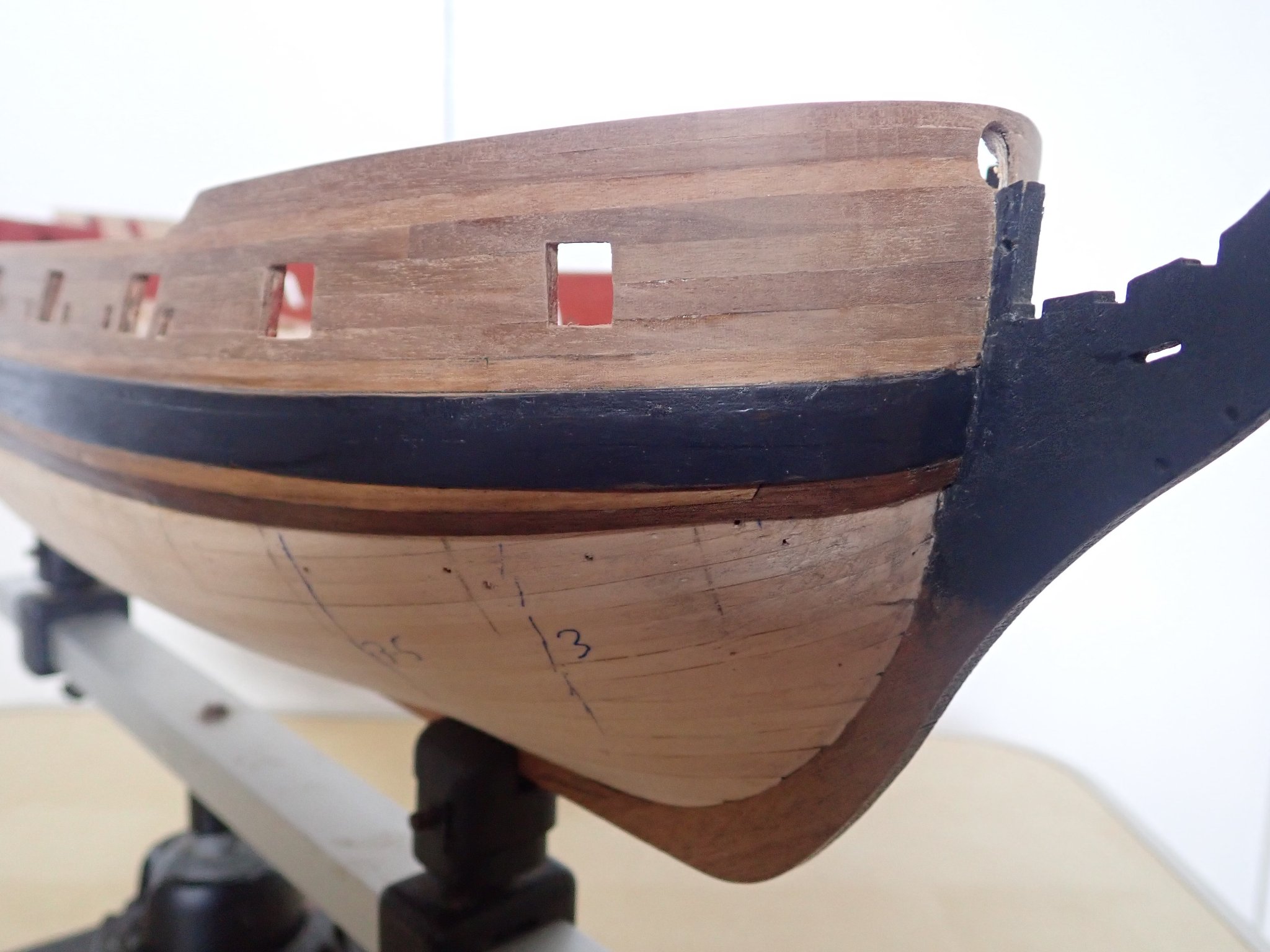
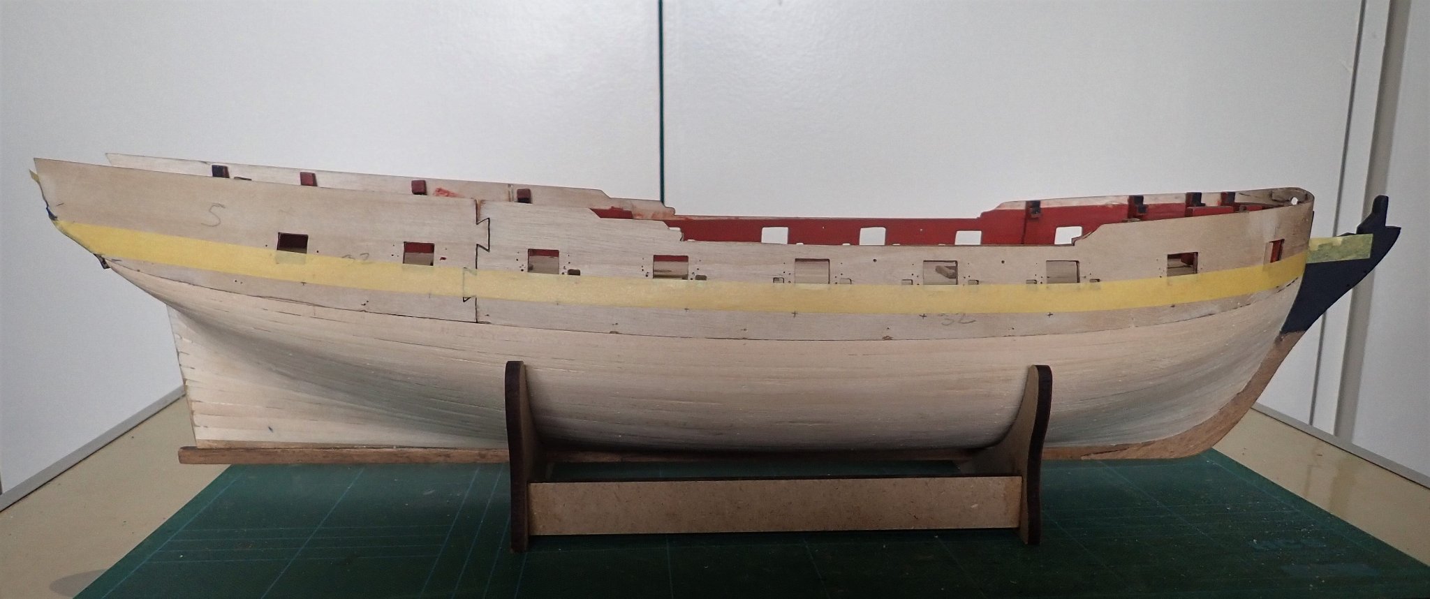
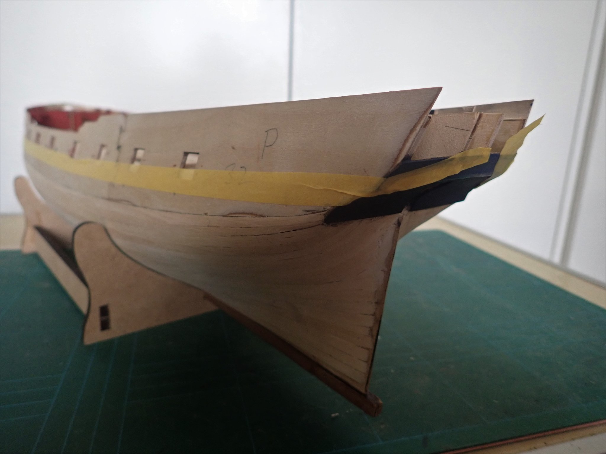
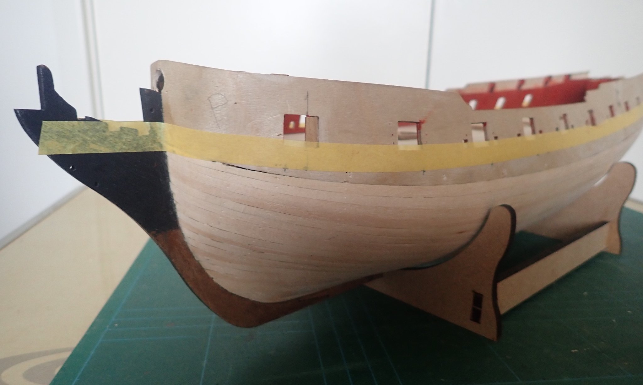
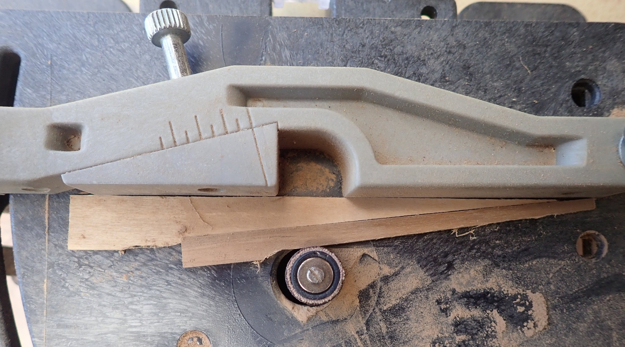
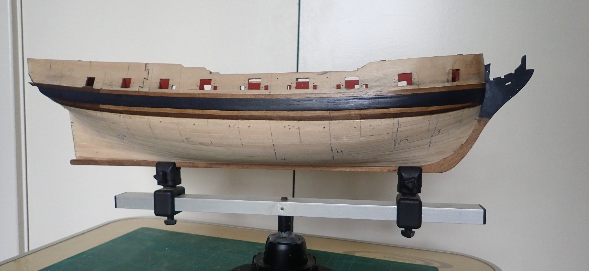
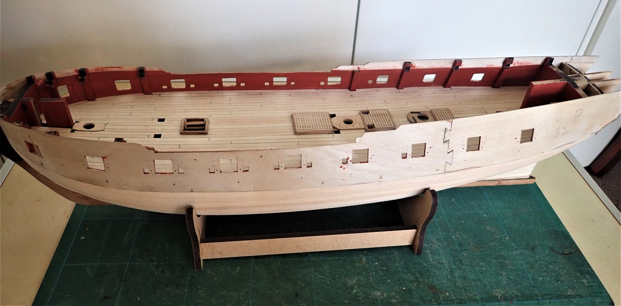
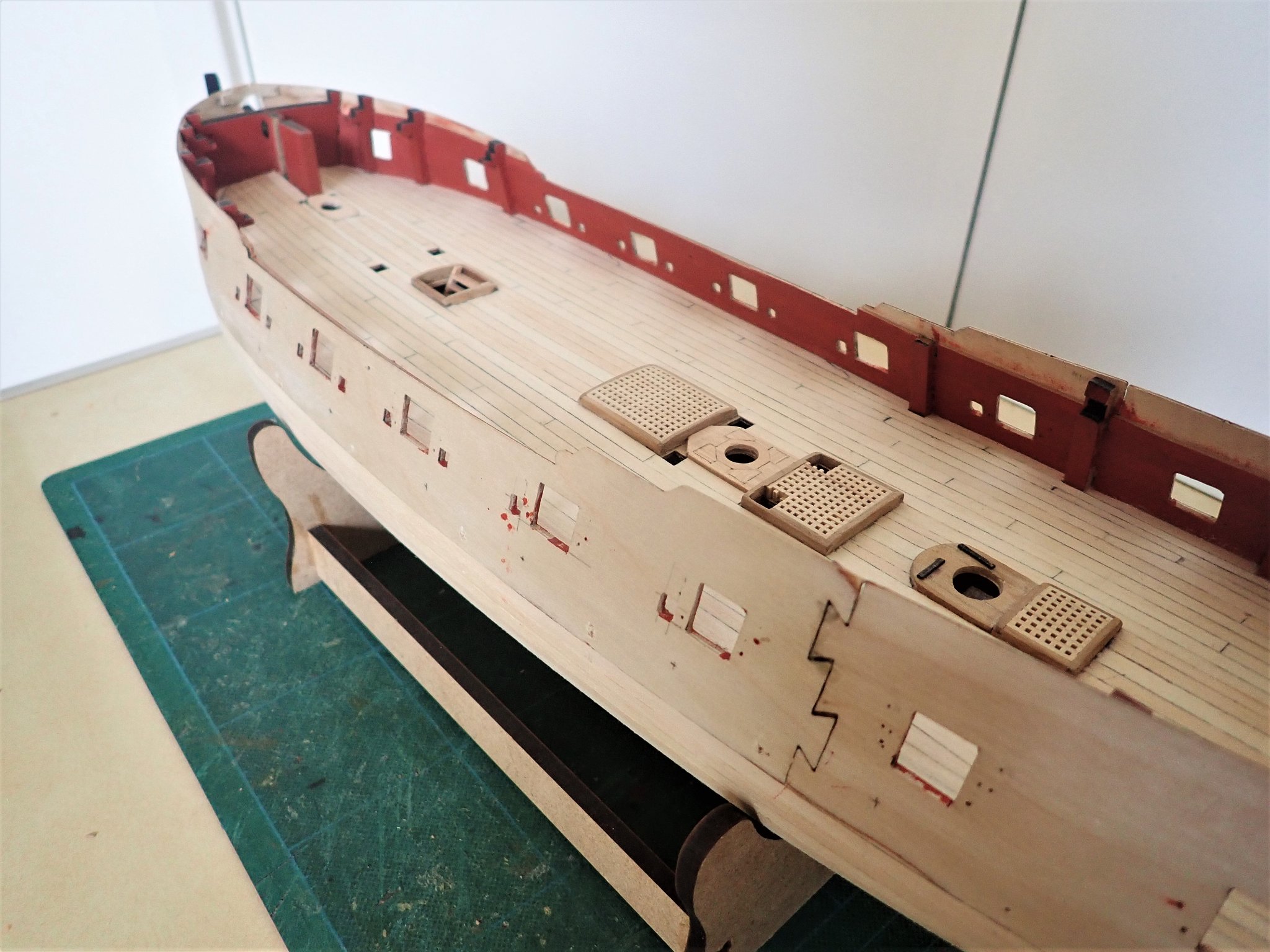
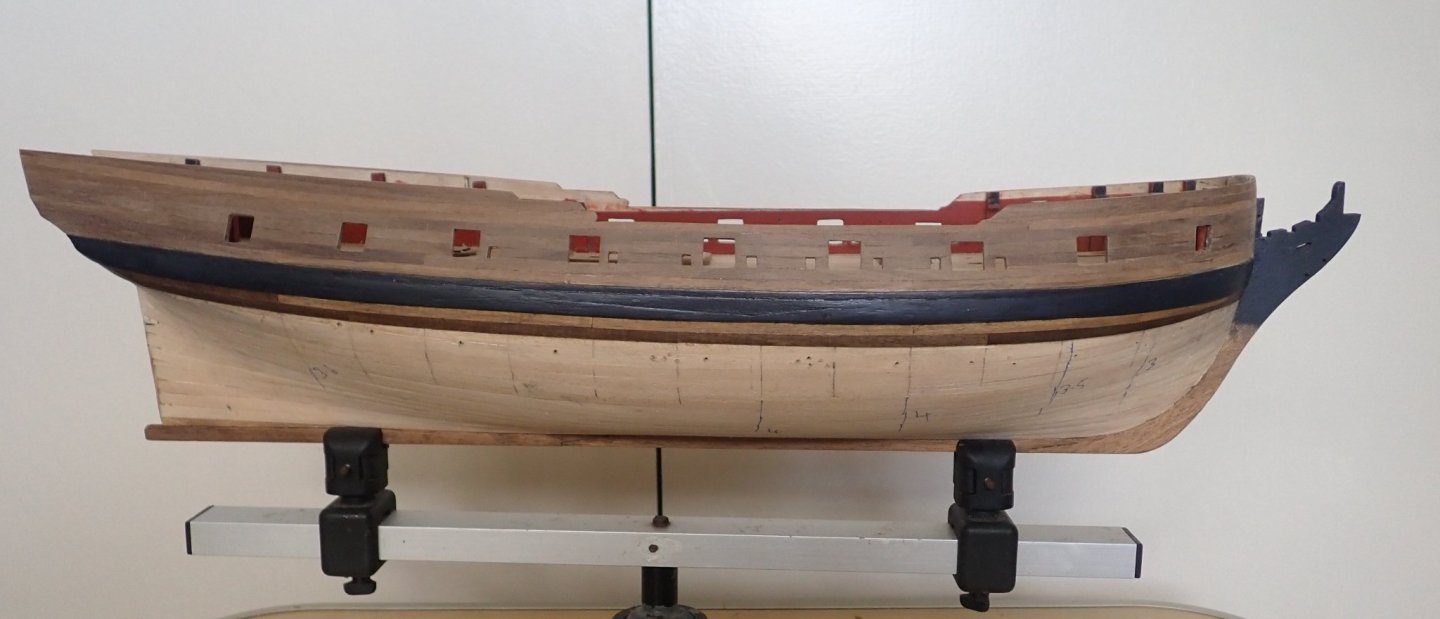
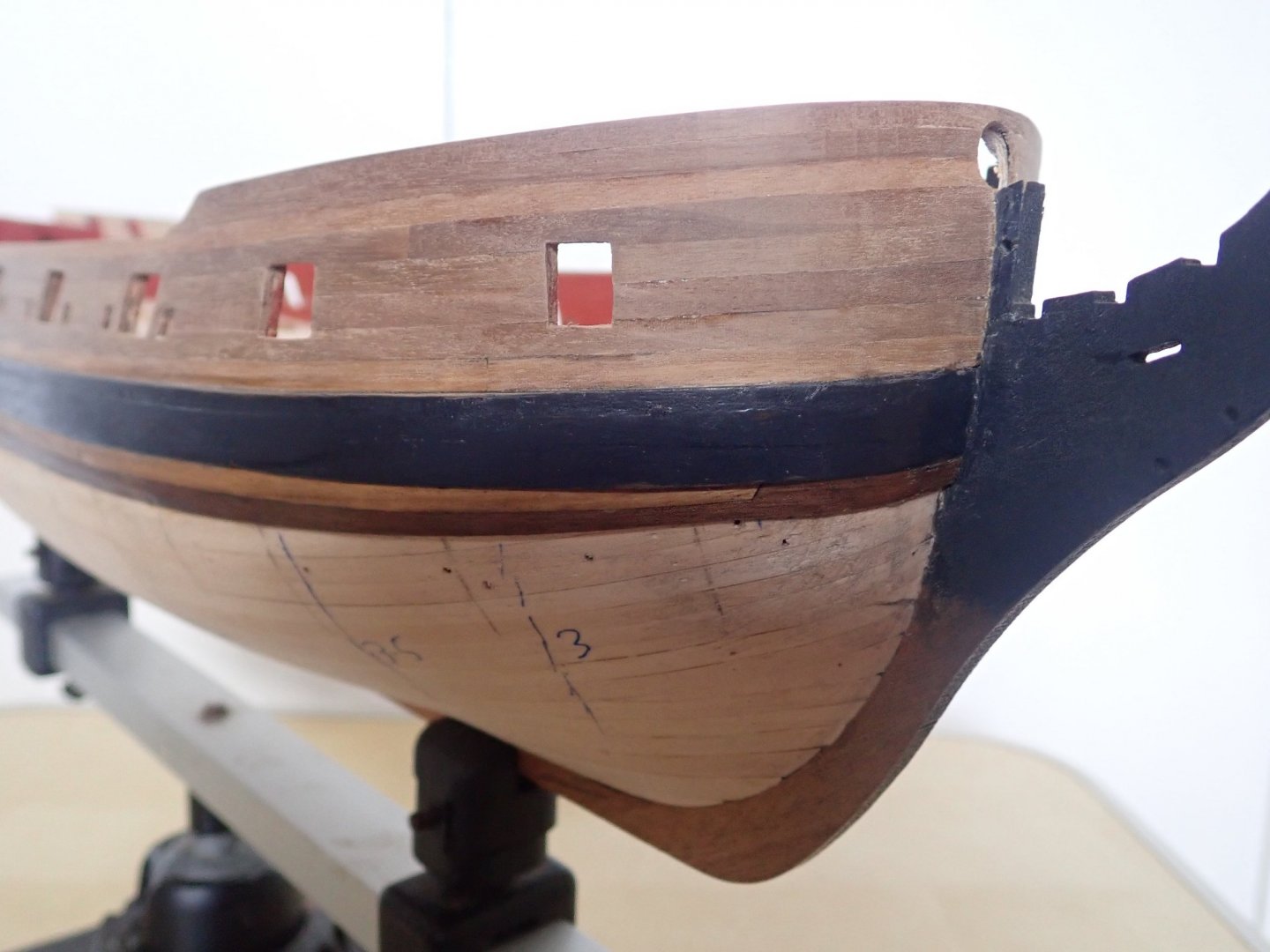
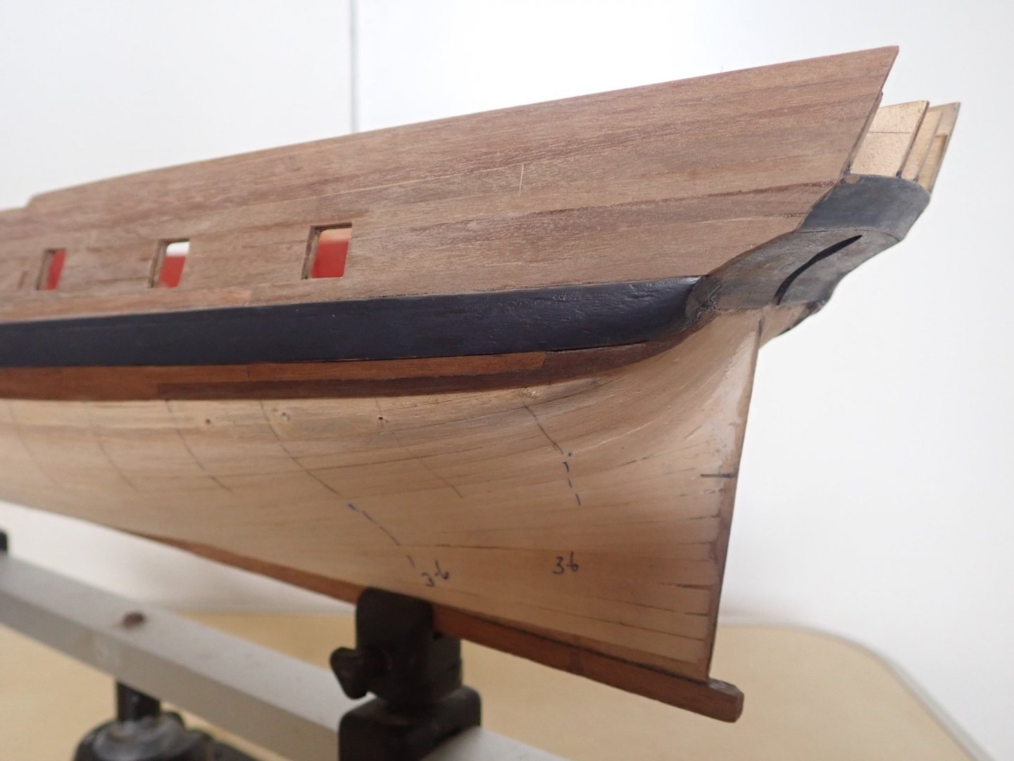
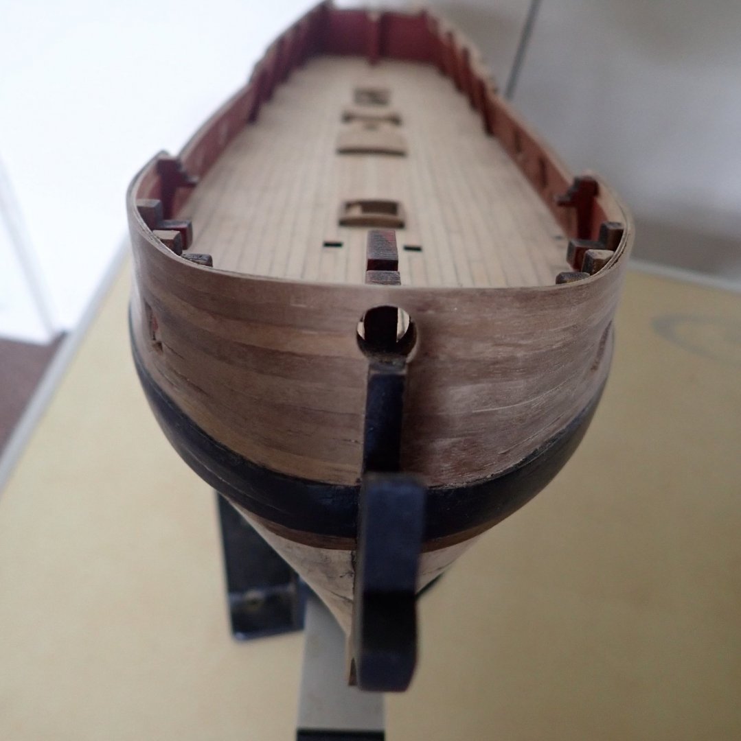
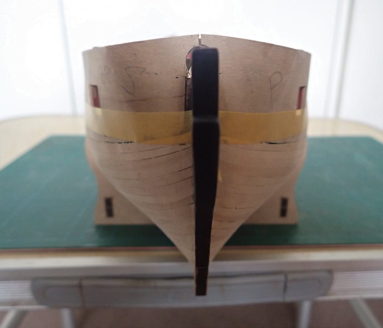
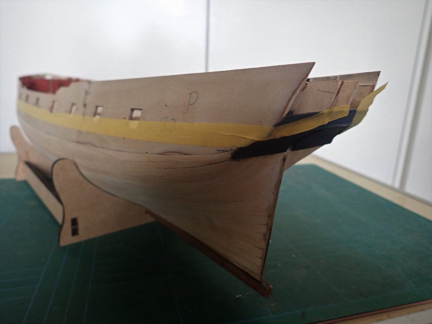
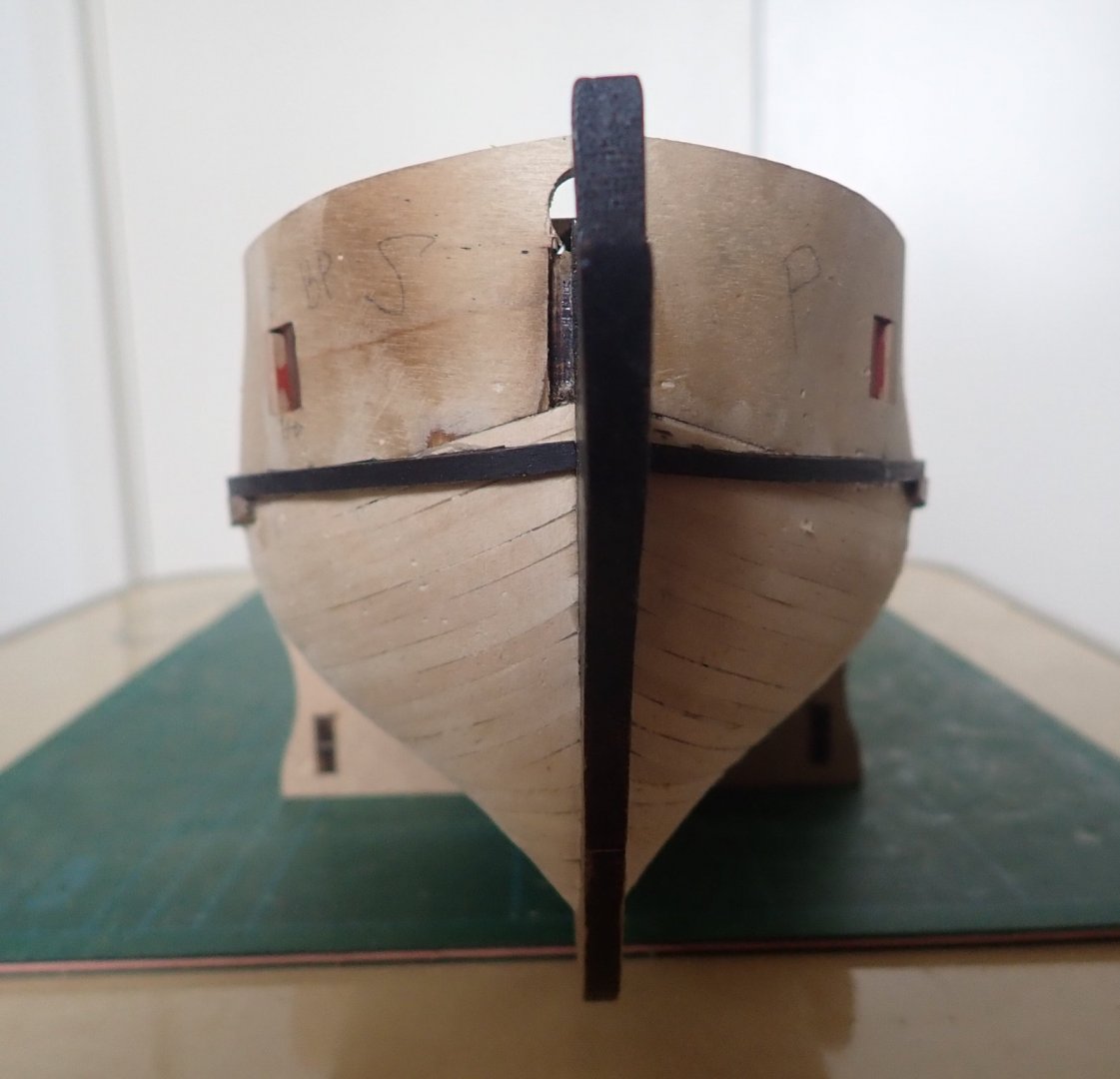
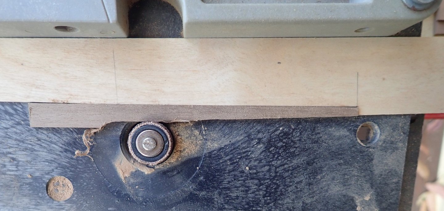
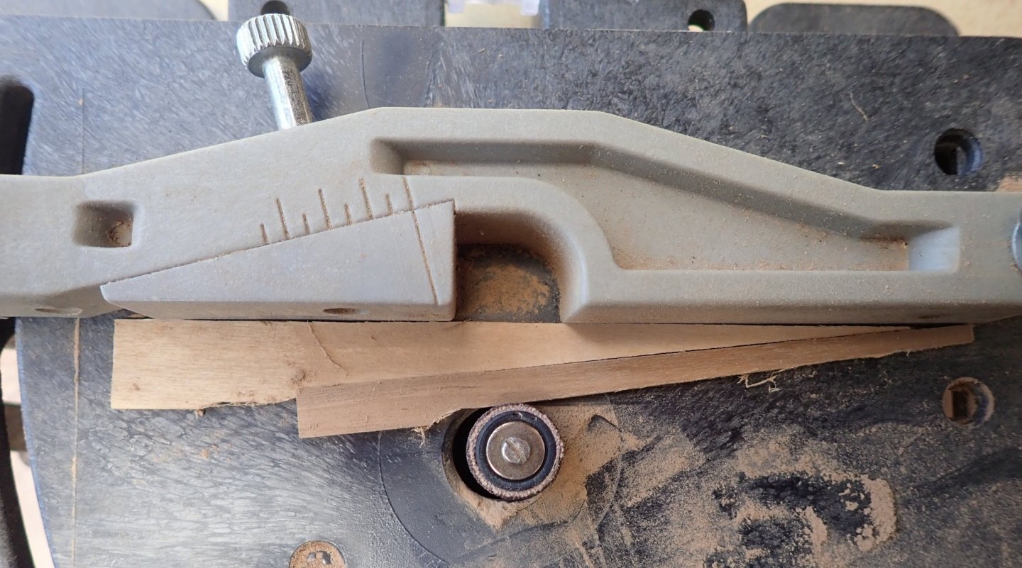
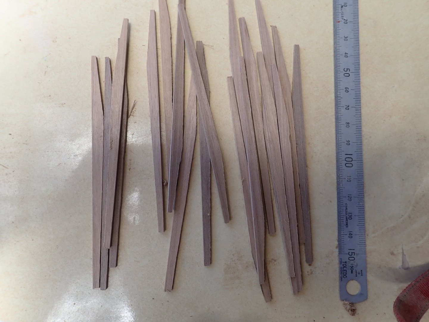
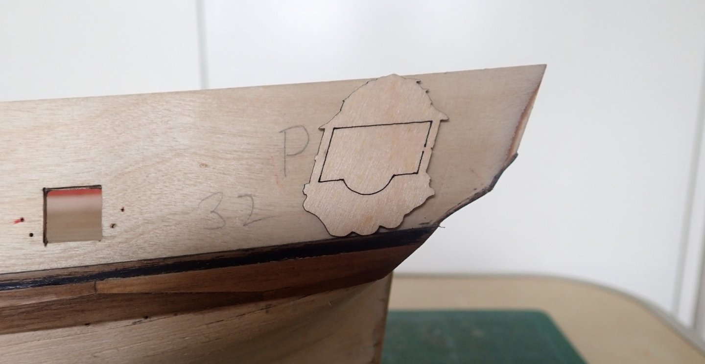
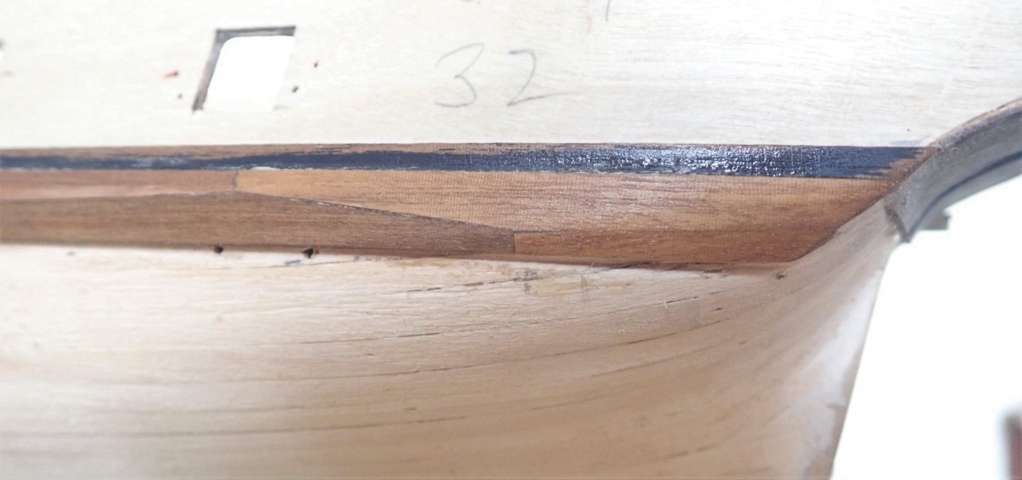
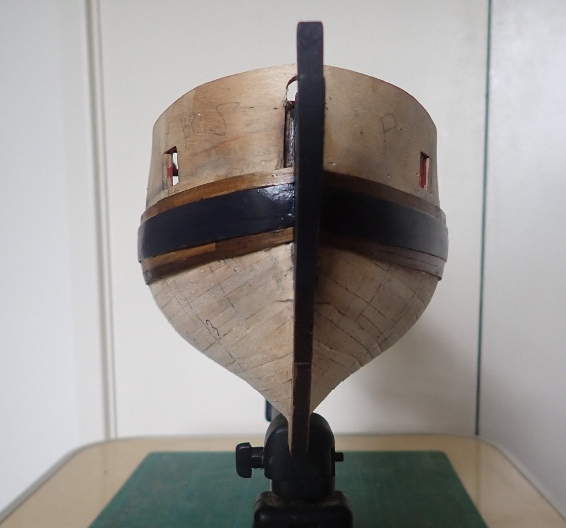
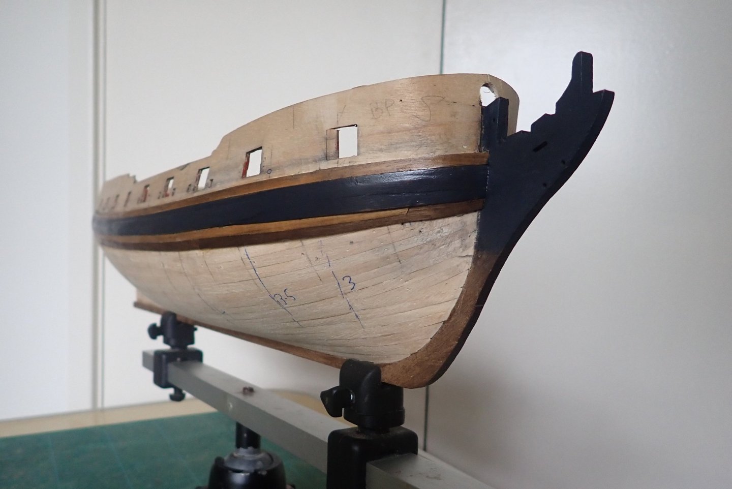
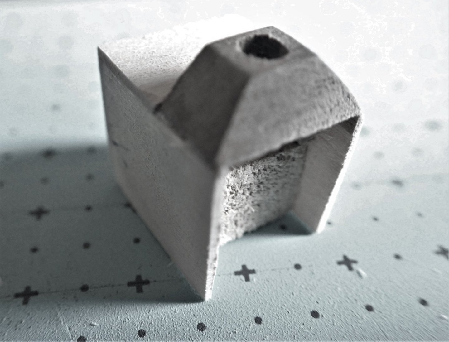
Thanks for the comment B.E., and yes, I did check the dimensions - several times in fact 🙂. So onto the wales and the second planking. The instructions say to completely cover the hull with the second planking, then overlay a third layer to represent the wales. I decided to install the wales first, then run the second planks above and below them. The planks for the second layer are 1x4mm, and this gives an apparent thickness of the wales, if the instructions are followed, of 2mm, and as three strakes are applied, a width of 12mm. In TFFM it shows that the wales consist of three strakes, the top one simple parallel planking, but the bottom two top-and-butt. Why not I thought. All three strakes are 2mm thick, the upper one is 3mm wide and the lower two have a combined width of 9mm. Total width therefore is 12mm, the same as the kit instructions and agreeing with that in TFFM. The position of the top of the wales was carefully marked, measuring down from the lower edge of the gunports as suggested. The actual positions at the stem and stern were a little tricky to get as there are a lot of decorations in these positions as shown on the plans. Tamiya masking tape was then used to show the run of the wales (the top edge). The hull was put aside for a while, then eyeballed again to see if the run was smooth. A very slight adjustment was made at the stem. The top strake was glued in place. The planks for the top-and-butt were shaped using a Dremel router table and a sanding drum. They were then cleaned up with a sanding block. The dimensions were taken from TFFM. The router table with a simple jig for the first pass, blanks on the right and some after the first pass A blank after the first pass. Ready for the second pass using another simple jig. The planks ready to be finished with a sanding block. At the stem, the first couple of planks were individually shaped to fit the rather complex curves there. Commencement of the first top-and-butt strake. The port wale complete. The last short plank of the lower strake was a little tricky to get right due to the compound curves there. The completed wale and the start of the second planking - one strake done above the wale and two below. Scale length planks were used. Unfortunately, the details of the top-and-butt are hidden by the paint (but I know they're there 😊). A drop plank can be seen at the bow, and there is a similar one at the stern. At the stem, the wales were thinned to 1mm, the same thickness as the second planks, as on the actual ship, the wales and the hull planks fitted into the same rabbet. This is mentioned in TFFM and also by Chuck in his instructions for the Winchelsea. At least one build log warns against allowing the wale to be too high at the stern, as if it is, the quarterlight won't fit. I remembered this warning after I had completed the wale, but as the photo shows, all seems good though a slight sanding may be required (just ignore the fact that I have actually put the quarterlight on upside down 😖). That's it for now, cheers.


- 104 replies
-
- 5
-
-
- pegasus
- victory models
- (and 2 more)
-
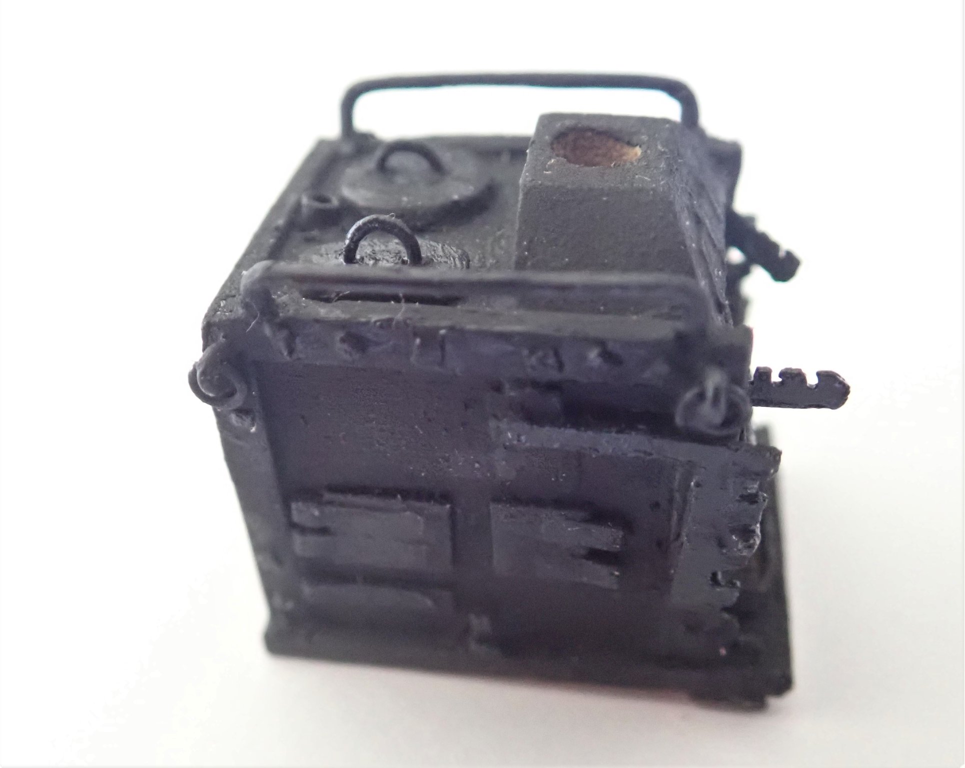
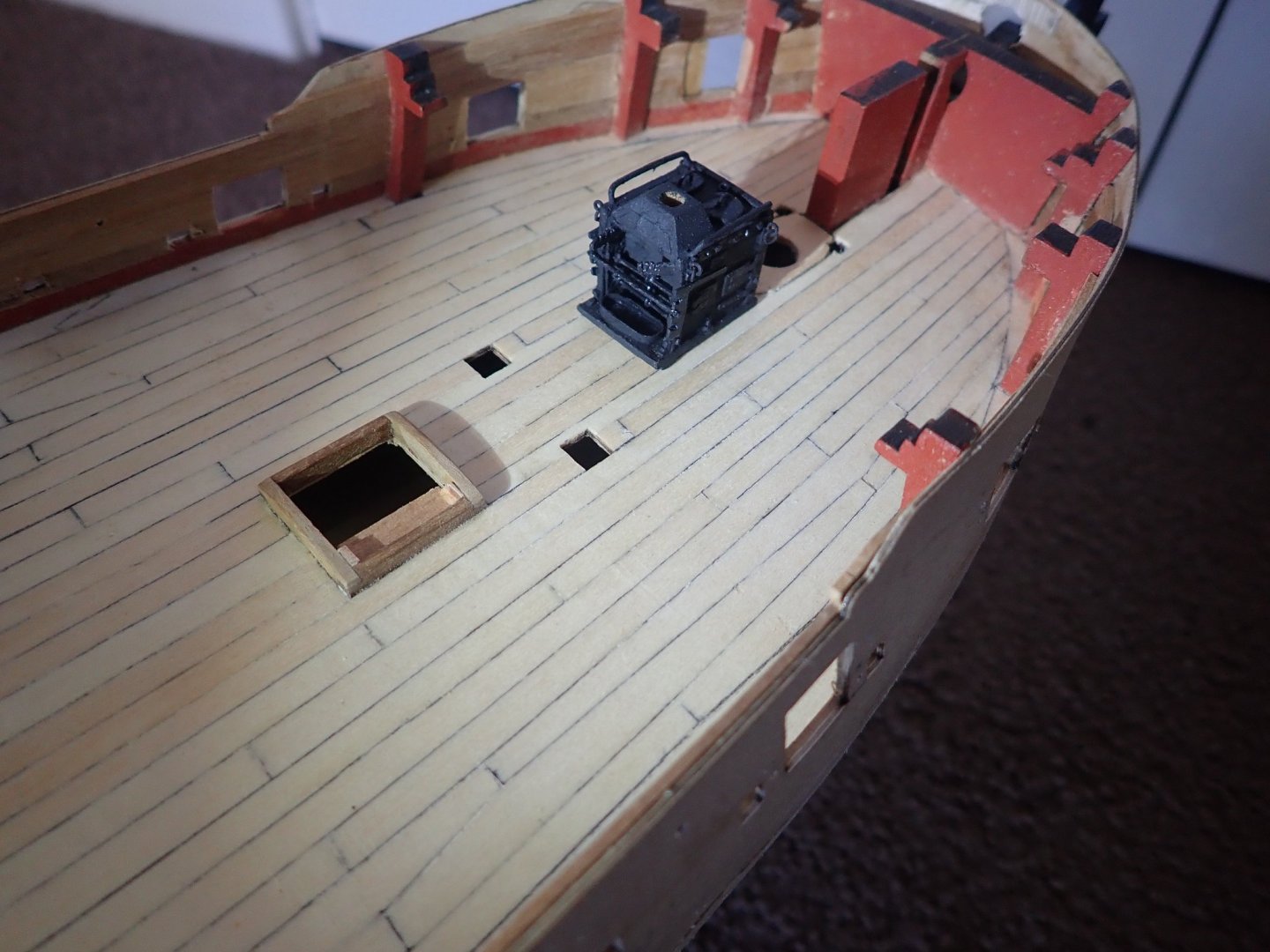
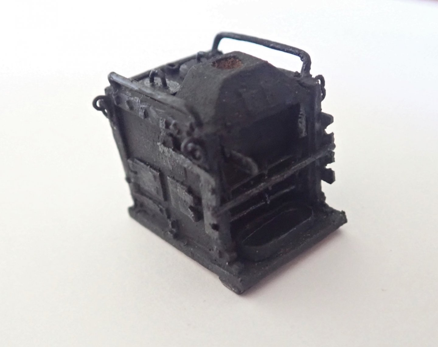
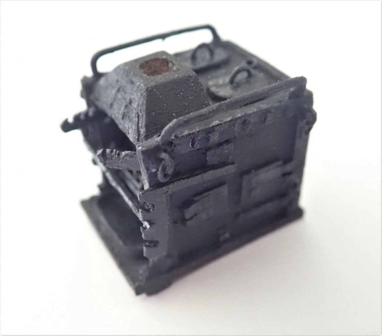
Thanks for the likes everybody. Along with some others, I decided to make the stove (Blue Ensign and Alistair in particular inspired me). I followed the diagrams in TFFM and made it slowly over a period of several weeks. Although small, I used a wide variety of materials to make it - wood, bamboo, cardboard, paper, metal, plastic and thin cord. It was fiddly to make but not especially difficult. The basic body is wood, L-shaped styrene was glued along the edges and very small squares of styrene were used to represent the boltheads. The doors on the sides are thin cardboard and the hinges are a thin bamboo dowel glued to paper and then cut into strips. Holes were drilled into the sides and bamboo dowels were pushed through to represent the fire grate bars. The supports/spacers for these are simply thin cord wrapped around them in a figure of eight pattern. The spit is likewise bamboo. The pot holders and the supports for the spit are plastic. The two boiler covers are wood with brass wire handles. The two bars along the sides are wire, paper clips actually as these looked to be of the "right" diameter. The drip tray has a wooden base with a paper strip wrapped around it. The beginning and the finished stove. The hole in the top is to locate the chimney when I make it. It will be greater in diameter than that hole. The stove approximately in place on the deck. Cheers

- 104 replies
-
- 6
-
-
- pegasus
- victory models
- (and 2 more)
-
Welcome back.
-
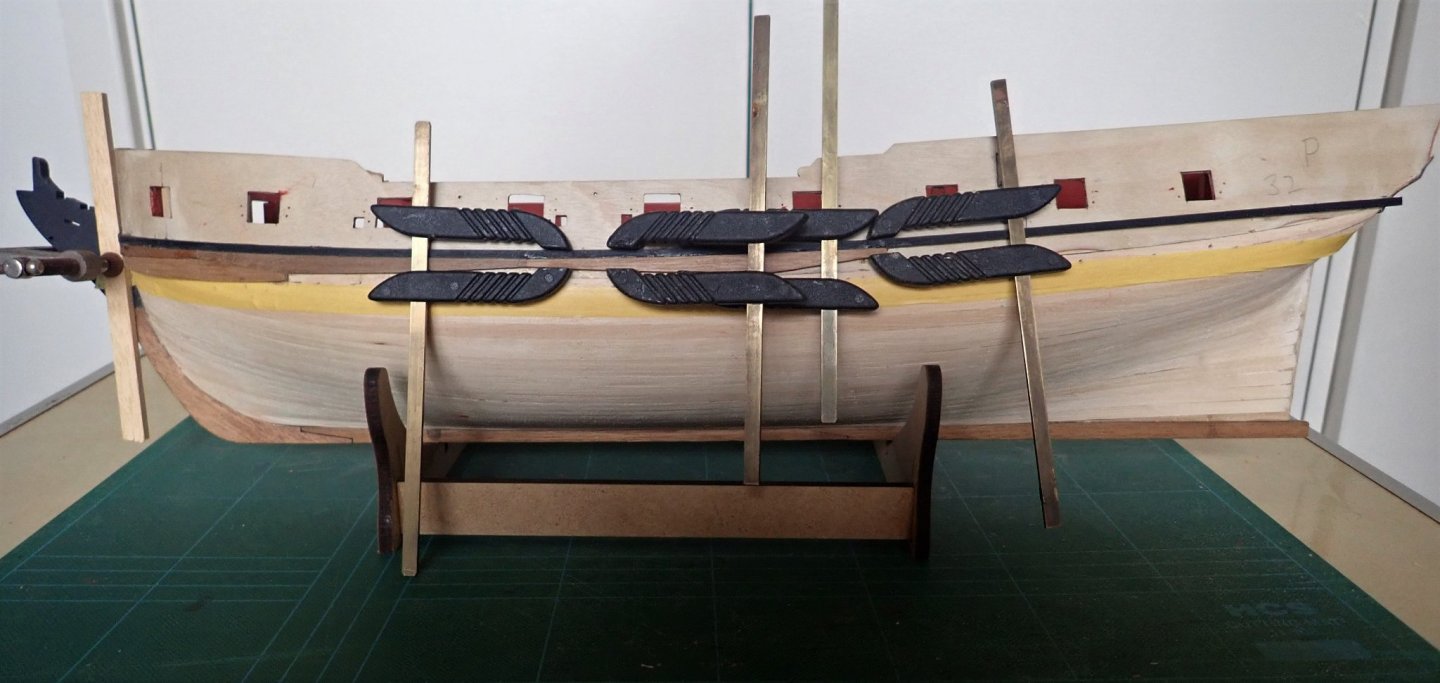
I have absolutely no idea of how long the sweeps would have been, but stowing them below would have been an interesting exercise in getting them through the hatch and onto the lower deck. Maybe they were lashed to the outside of the ship's sides. Or to the beams under the foredeck and quarterdeck. And you wouldn't be able to get much of a stroke when using them because the cannons would be in the way. Anyway, they are a bit of a pain on the model 🙂.
- 104 replies
-
- 1
-
-
- pegasus
- victory models
- (and 2 more)
-
That looks good Starlight - well done.
-
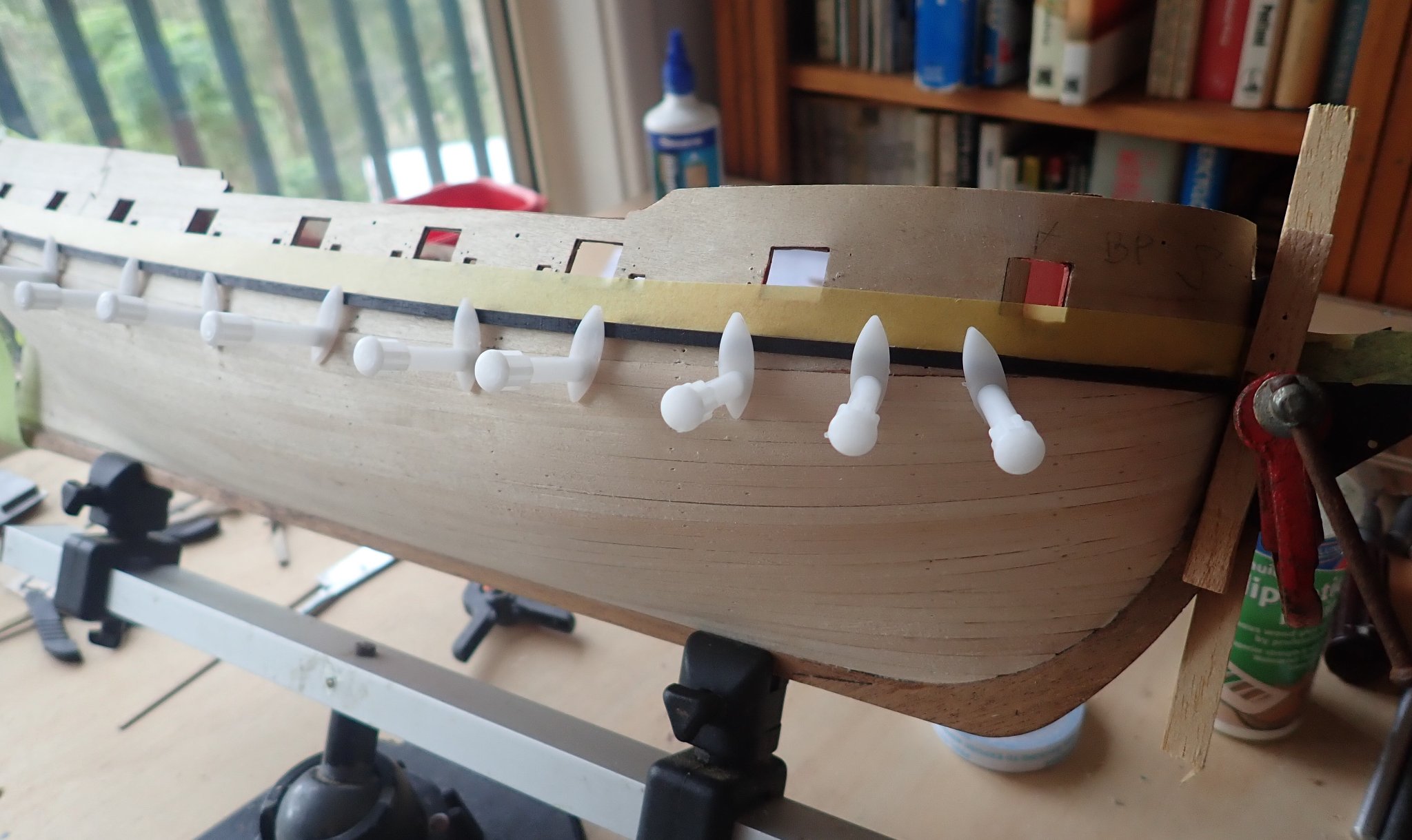
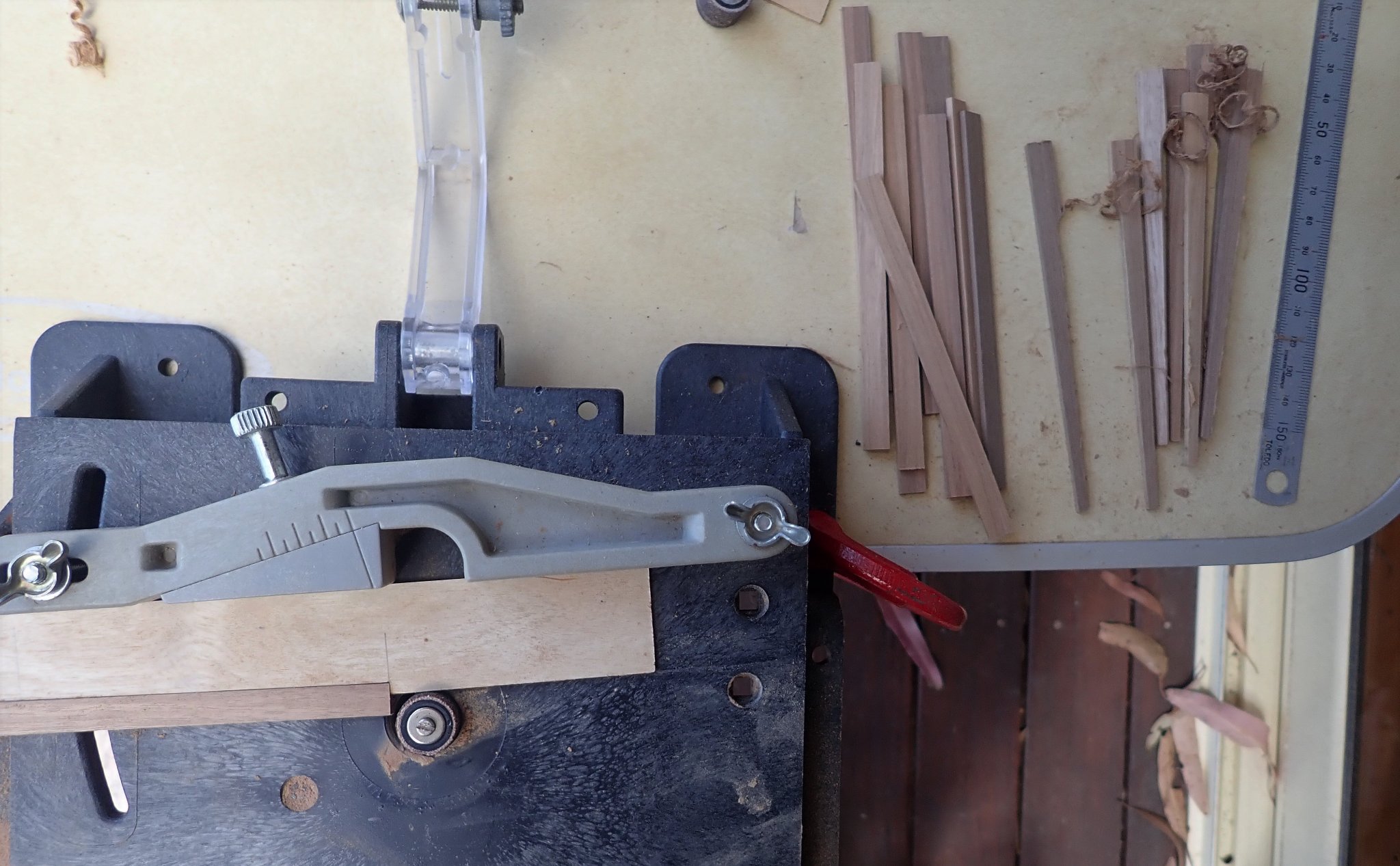
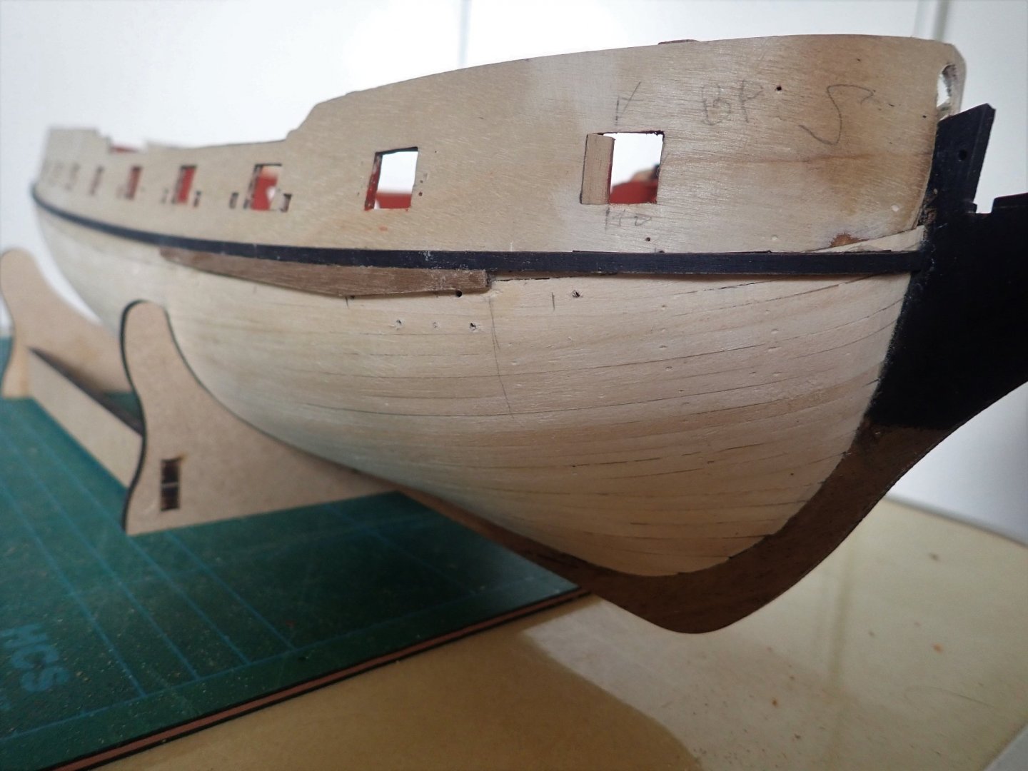
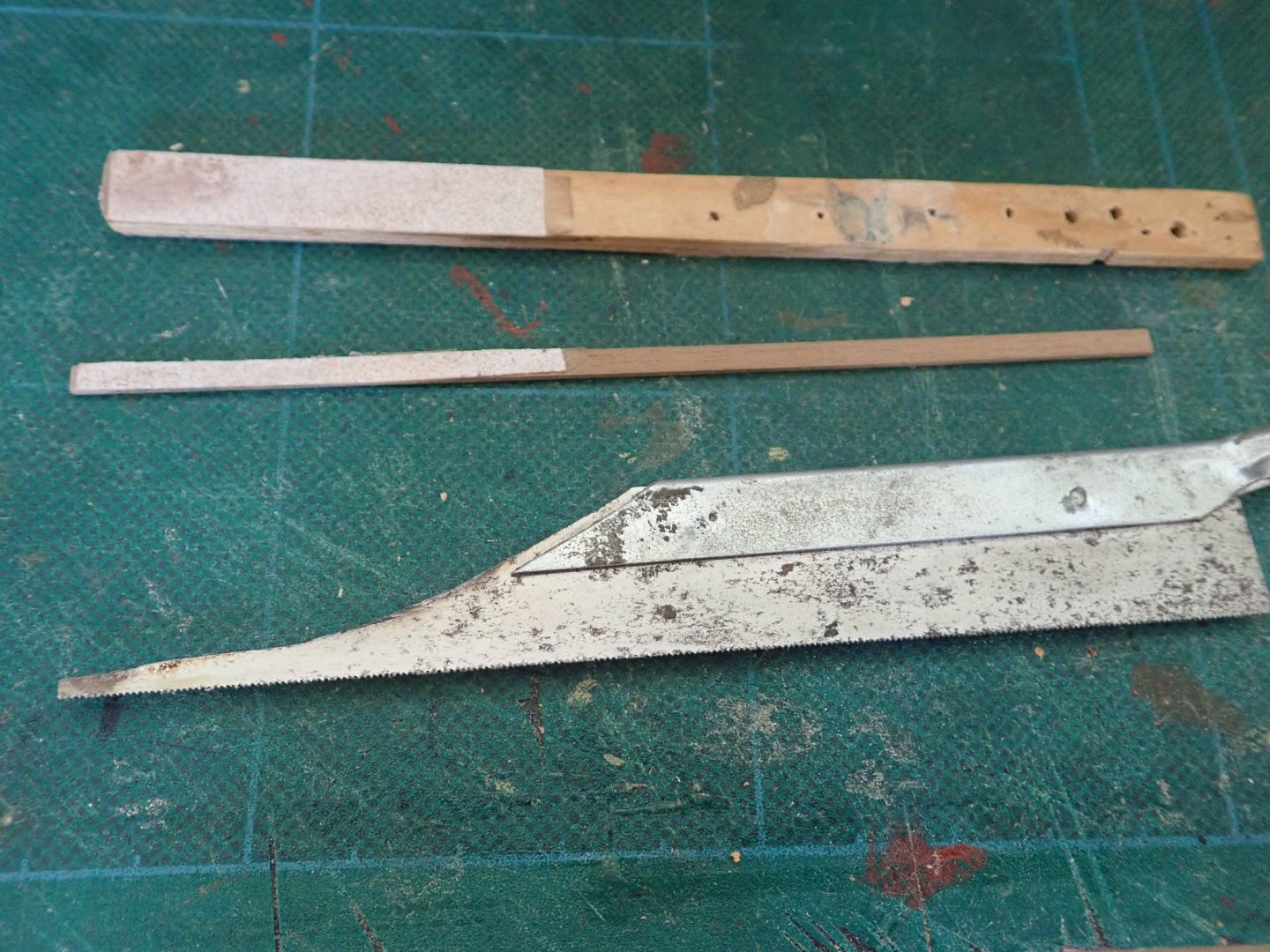
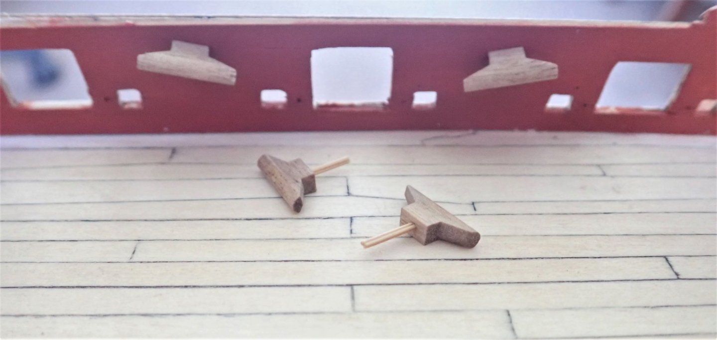
Thanks for the like BE. In an earlier post, I mentioned that I was thinking of planking the inner bulwarks before doing the second planking, in spite of the instructions telling you to do the reverse. The reason for this was because I planned on drilling the gunport pattern (before fixing) with the holes needed for the cannon eyebolts that are fixed into the inner bulwarks. After planking the bulwarks, I could then drill through them, using the gunport pattern as a guide. Doing it this way seemed to me to be far easier than trying to locate and drill the holes from inside the hull after the second planking was finished. There was no chance either of drilling right through the outer planking. And that’s what I did. It needs to be mentioned that if you do plank the bulwarks this way, you cannot quite finish as the beam (Part 38) has to be in place first. This slides into place, and cannot do so if the planking is complete. This part is also somewhat fragile and can be broken if forced into place. In spite of SpyGlass’s warning, that’s exactly what happened. Not serious, but annoying. And installing the beam at this point, before doing the second planking, would be extremely risky. The first plank across a gunport was trimmed to open the port. A modified razor saw was used. This gave a gap and subsequent planks were easily trimmed again using the razor saw. The final gap was tidied up using a sanding stick. The sweep ports were an exercise in patience. I very, very carefully drilled a hole through the covering plank, opened this with needle files then completed opening the port using the smallest sanding stick I have ever had. The modified saw and the two sanding sticks are shown in the photo. While I was happily drilling holes, I also decided to drill four more to allow the cleats (Part 226) to be pinned through the bulwark rather than just being glued to it. The cleats were drilled themselves and thin bamboo dowels glued in. The two cleats have not been glued in and the dowels are yet to be trimmed. Cheers.


- 104 replies
-
- 7
-
-
- pegasus
- victory models
- (and 2 more)
-
You'll be right Rob, keep treading water and enjoy what you're doing - after all, it is just a hobby. 🙂🙂 Cheers