-
Posts
1,591 -
Joined
-
Last visited
Content Type
Profiles
Forums
Gallery
Events
Everything posted by John Ruy
-
Actually it helps me relax and steady my hands. 🍷
- 165 replies
-
- Red Jacket
- Marine Model Company
-
(and 2 more)
Tagged with:
-
Yes… 1/16”=1’ is challenging for sure.
- 165 replies
-
- Red Jacket
- Marine Model Company
-
(and 2 more)
Tagged with:
-
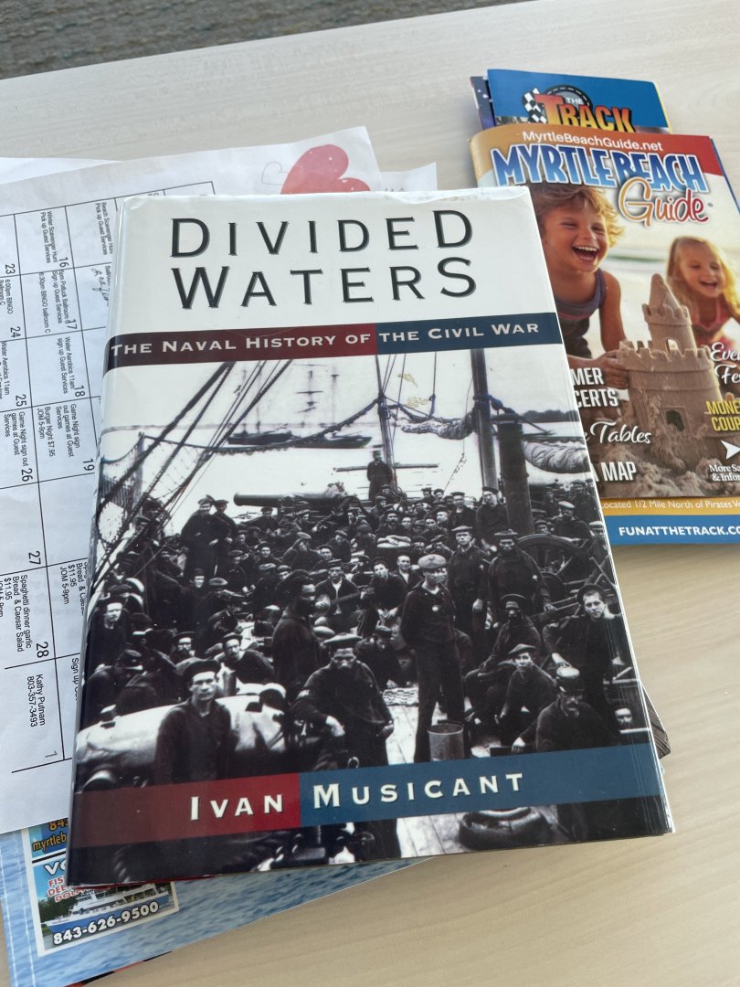
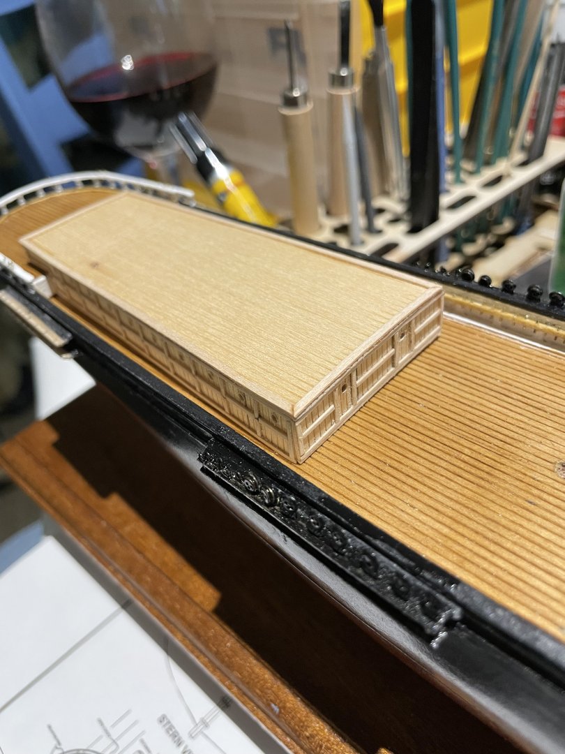
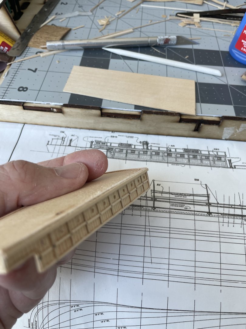
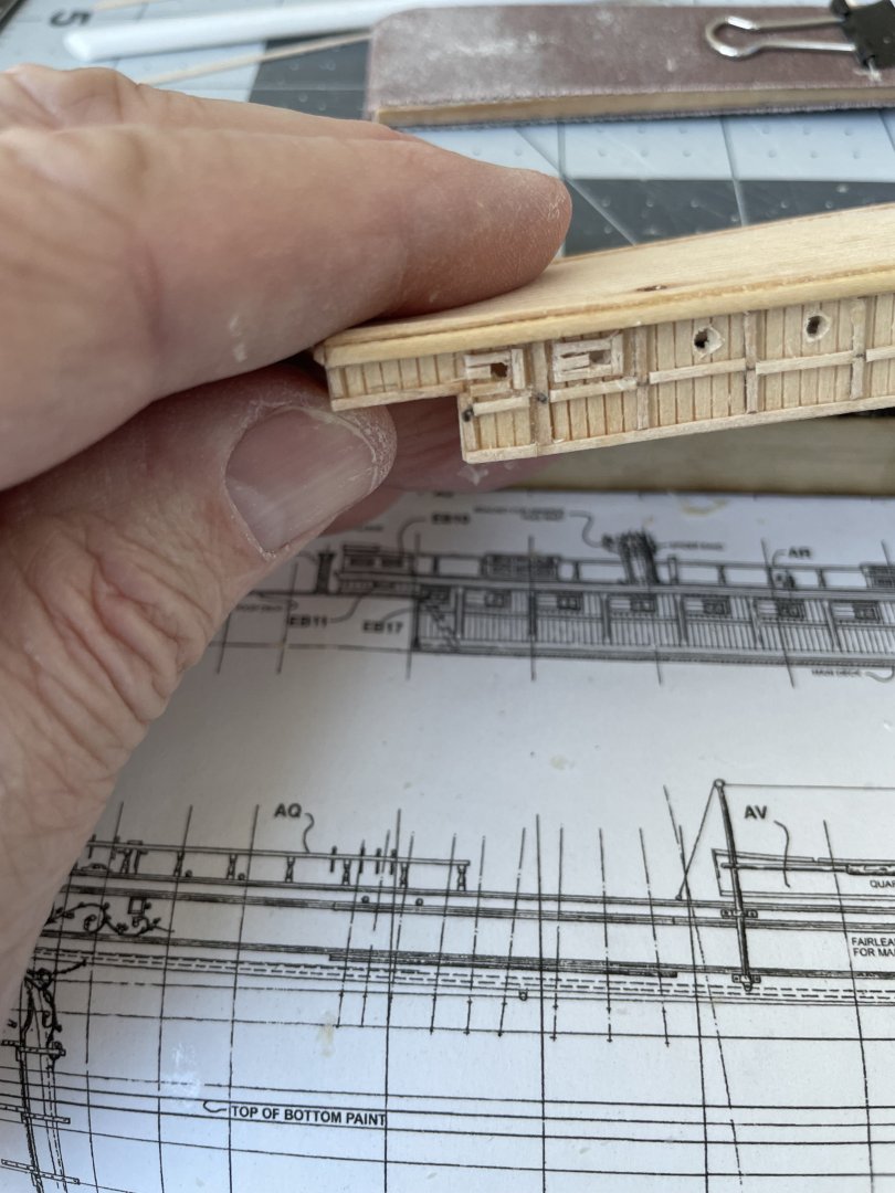
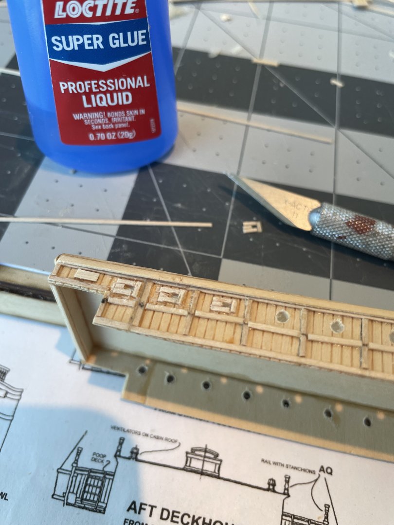
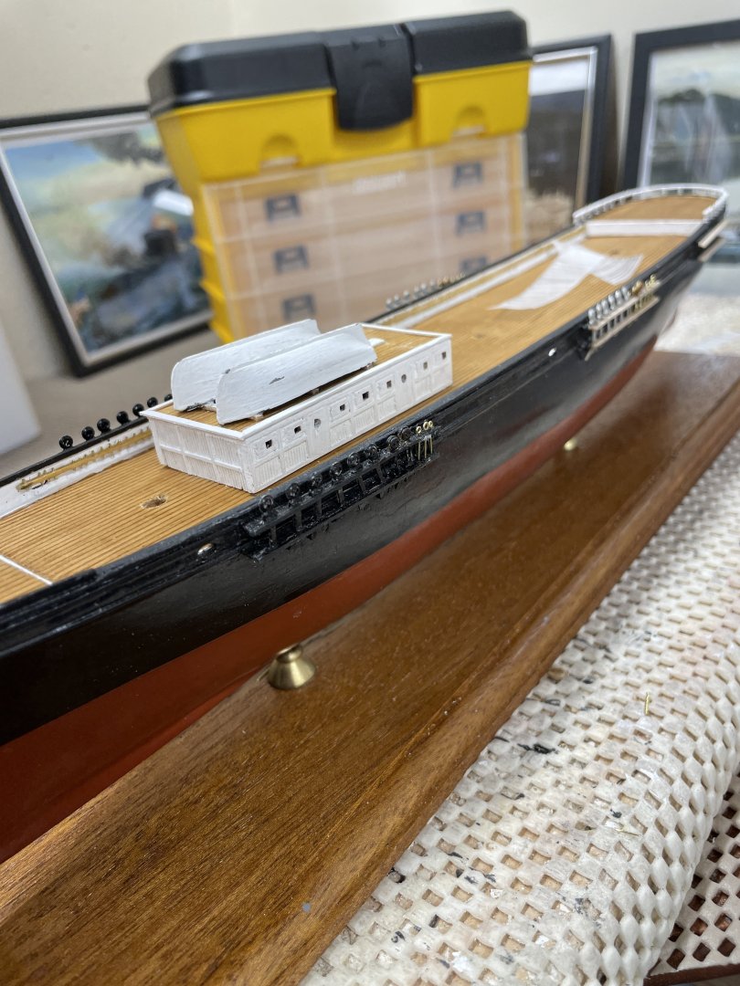
Thanks Bob… Your comment helps me to not complain about our overcast 50 degree weather. LOL 😆 Our tour of the French Quarter in Charleston was on a sunny 75 degree day. 😎 Glad I did… we have had some pretty gloomy cool weather. I was able to build the Aft Deckhouse these last couple of days. But the sun is out and we are off to see something, It’s good to get out and about. Maine is about to get hit with its first Noreastah Sunday. Besides, I need to do some research on the CSS Virginia and the Monitor. Cheers 🍻
- 165 replies
-
- Red Jacket
- Marine Model Company
-
(and 2 more)
Tagged with:
-
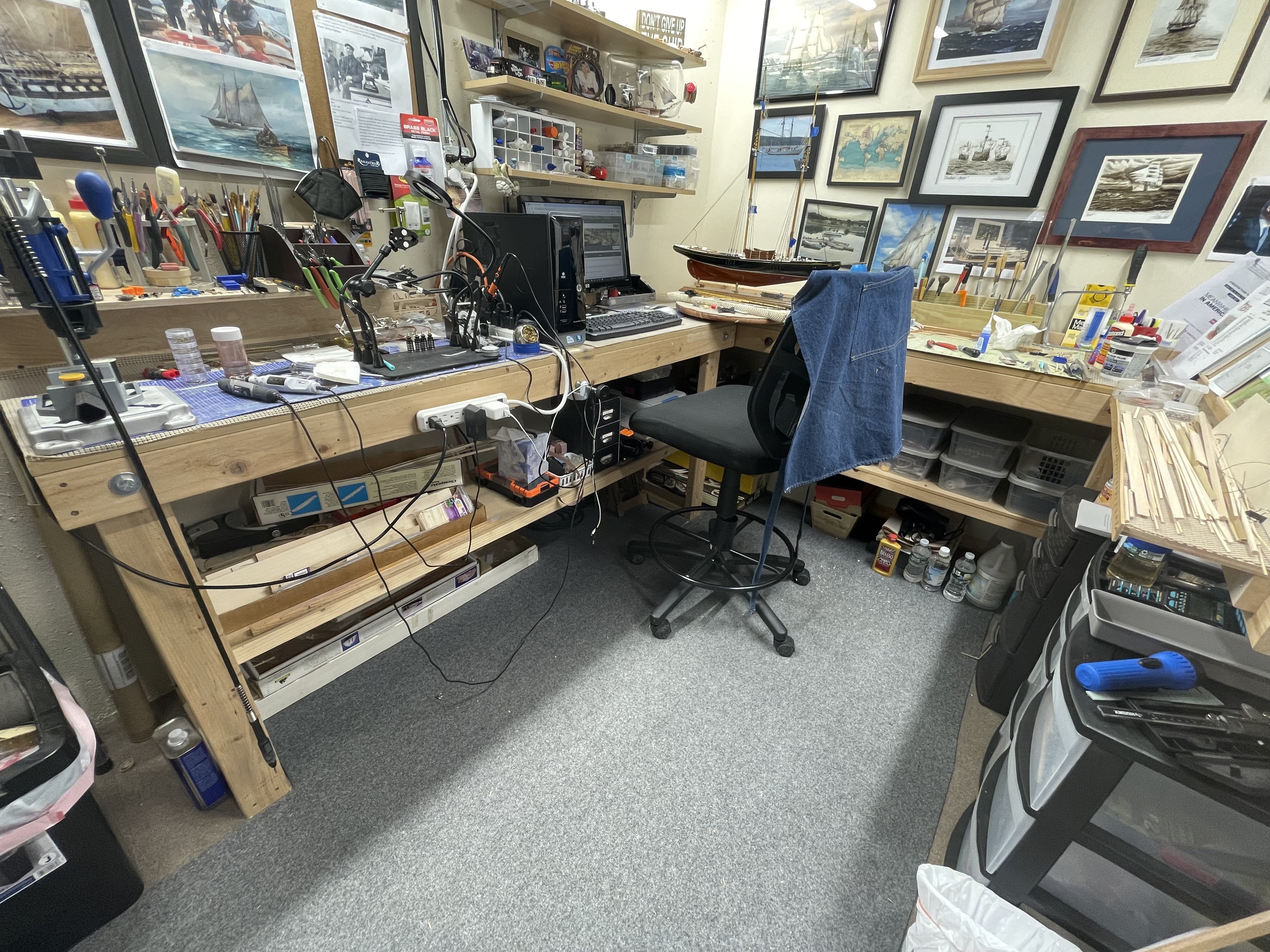
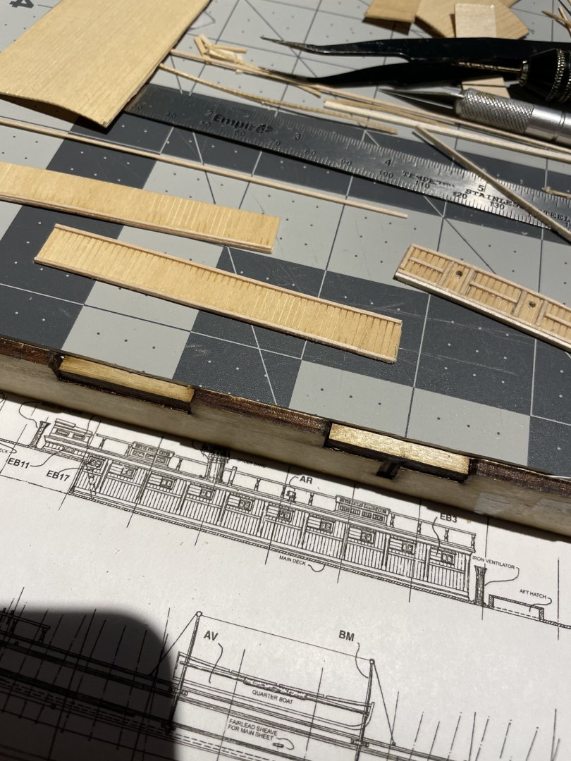
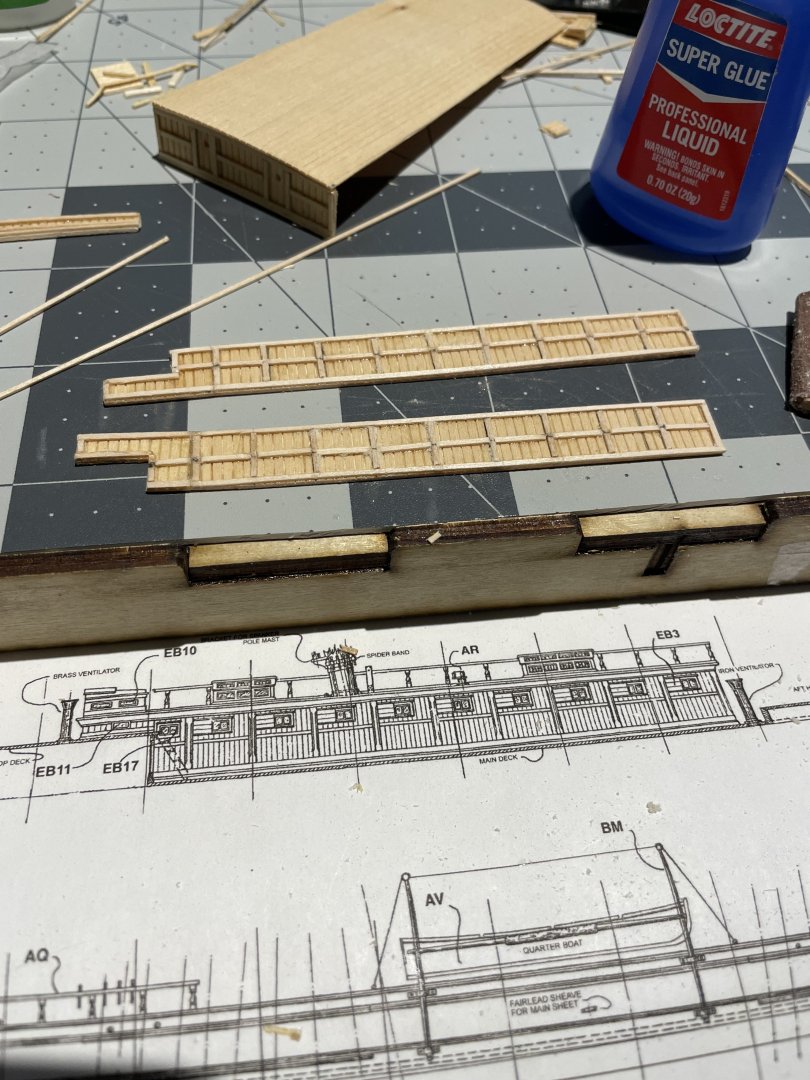
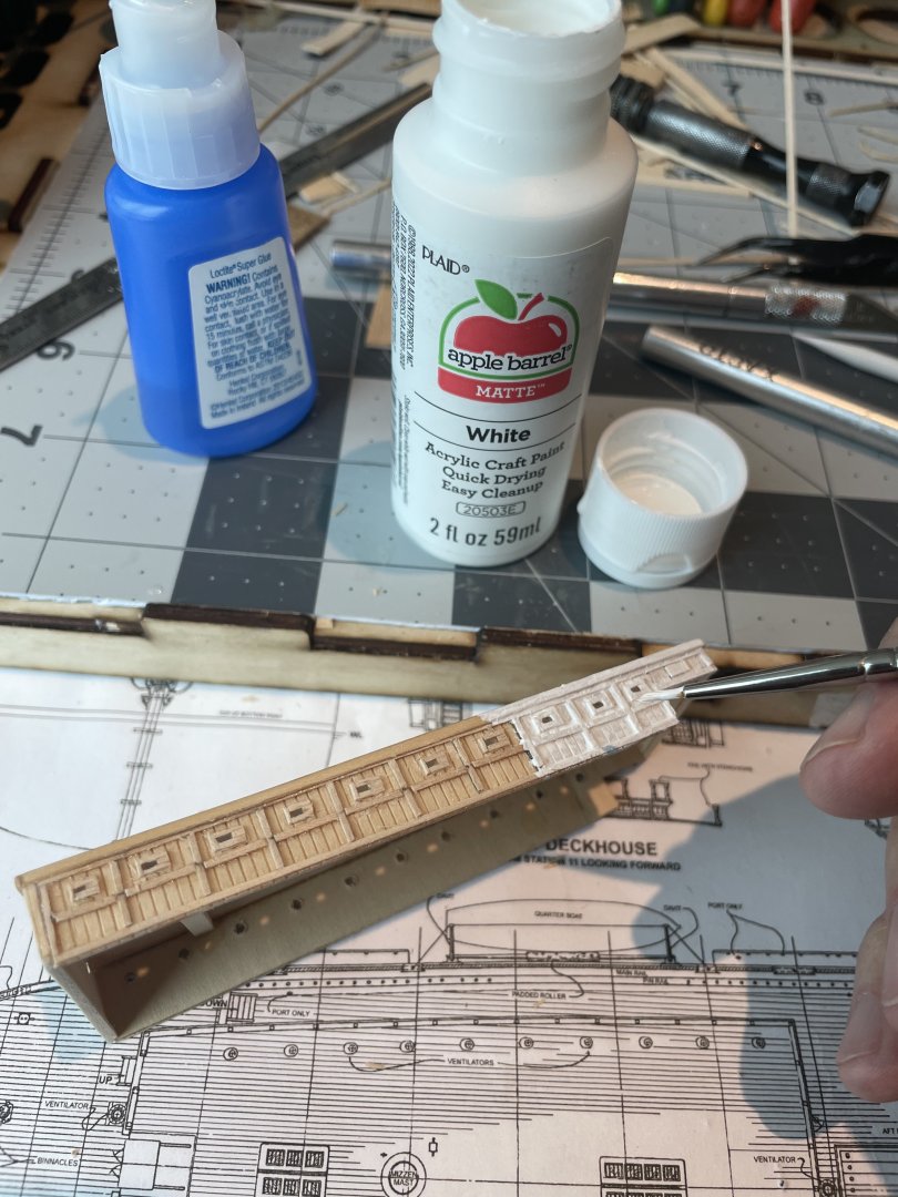
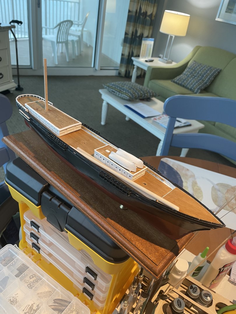
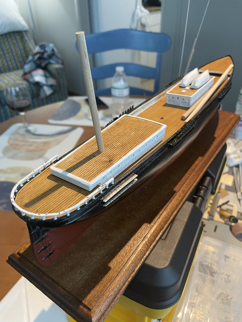
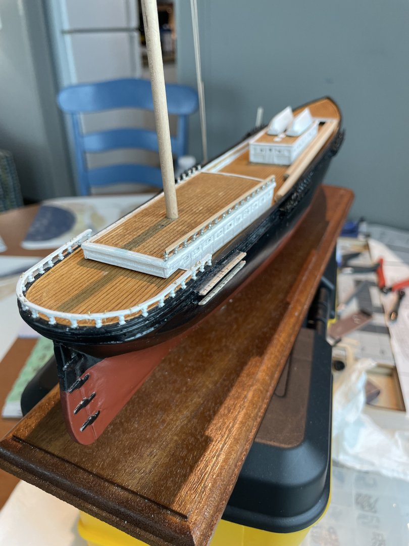
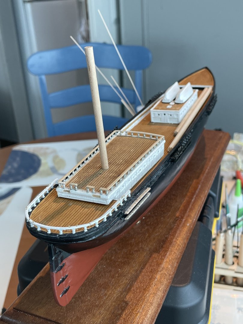
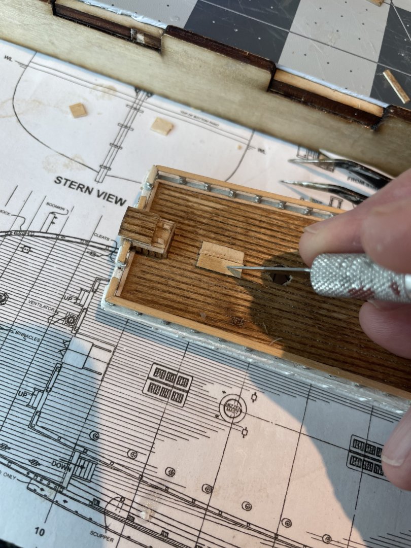
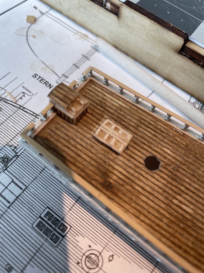
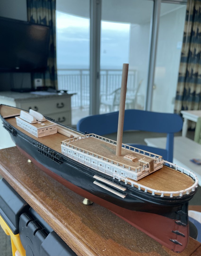
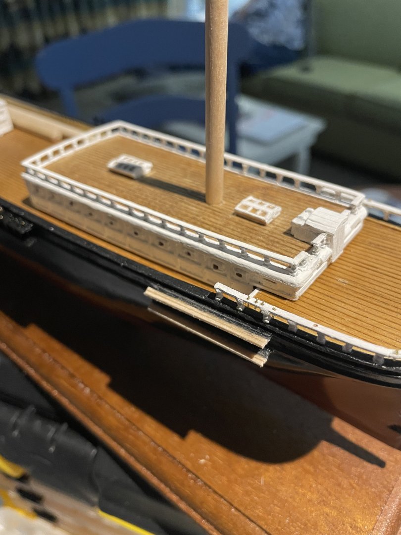
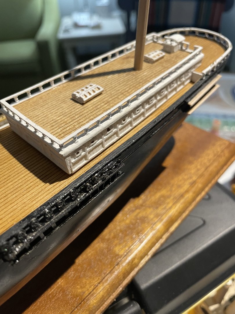
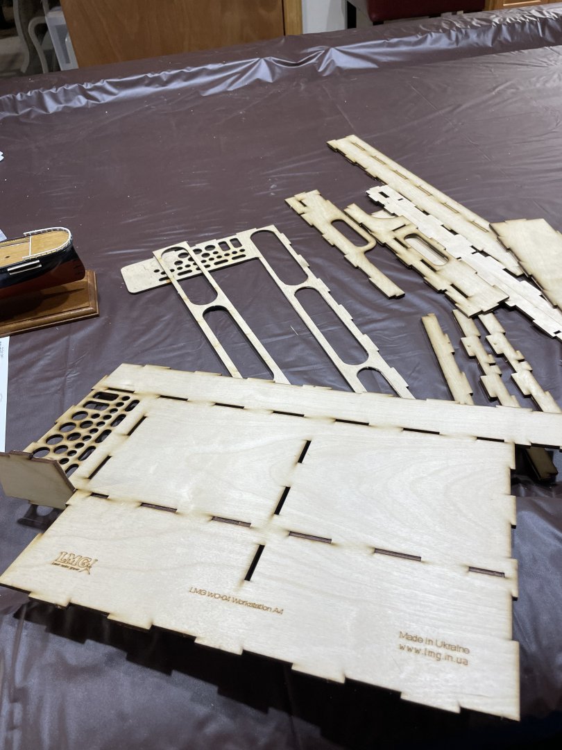
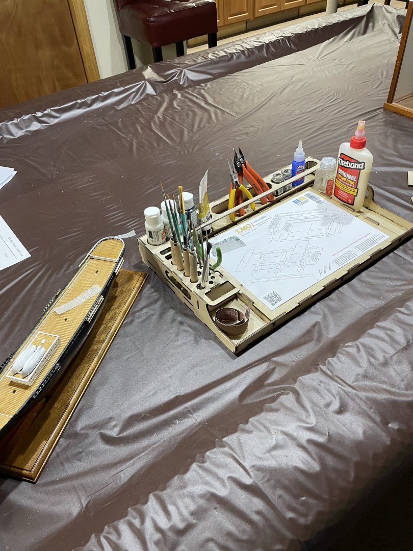
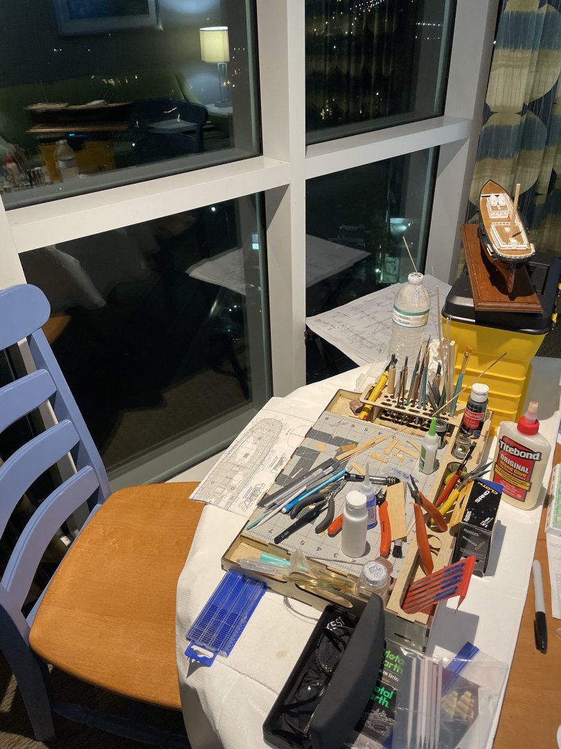
Remote Shipyard… The Wife and I decided we would fly south for the winter. Maine winters can be pretty brutal, so we decided February would be a good month to take a winter break and go south. I needed a way to take The Redjacket with me. So I bought a modeling tray and created a remote shipyard. Purchased on eBay from Ukraine. Some assembly required. 🤔 All set… Remote Shipyard is now established on the 11th floor of our resort hotel in SC. 😎 Aft Deckhouse Aft Deckhouse completed. Cheers 🍻
- 165 replies
-
- Red Jacket
- Marine Model Company
-
(and 2 more)
Tagged with:
-
Beautiful… Congratulations Bob wonderful job. It’s been a real kick to pull up a chair 🪑 John 🍻
- 207 replies
-
- vanguard models
- Duchess of Kingston
-
(and 1 more)
Tagged with:
-
Congrats Bob… Very nice work! Cheers 🍺
- 207 replies
-
- vanguard models
- Duchess of Kingston
-
(and 1 more)
Tagged with:
-
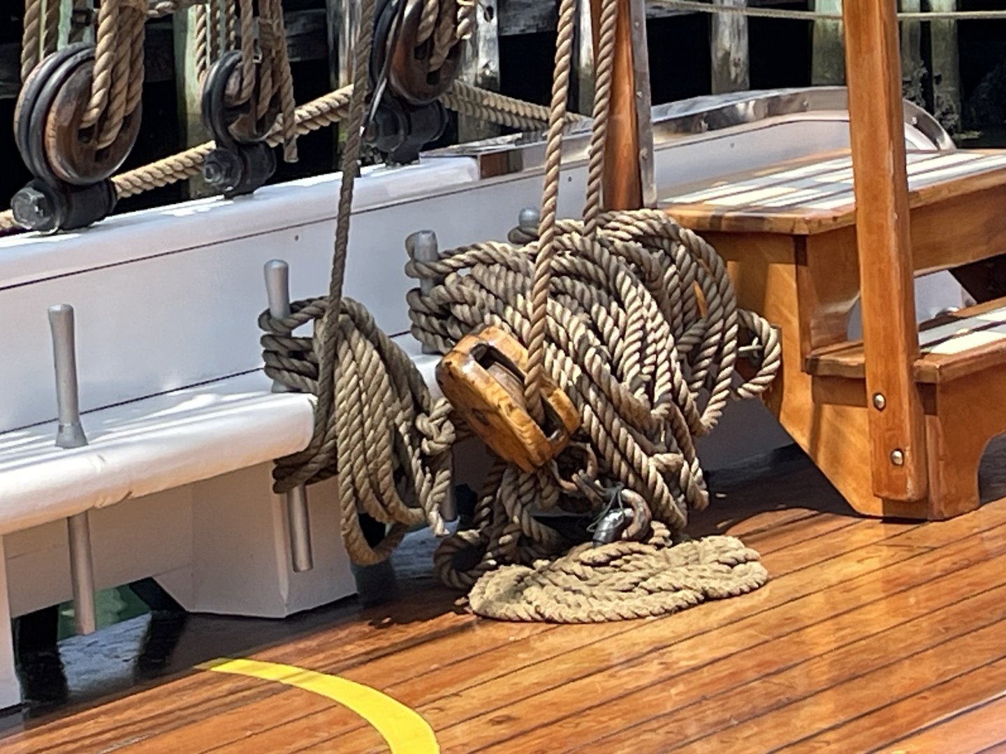
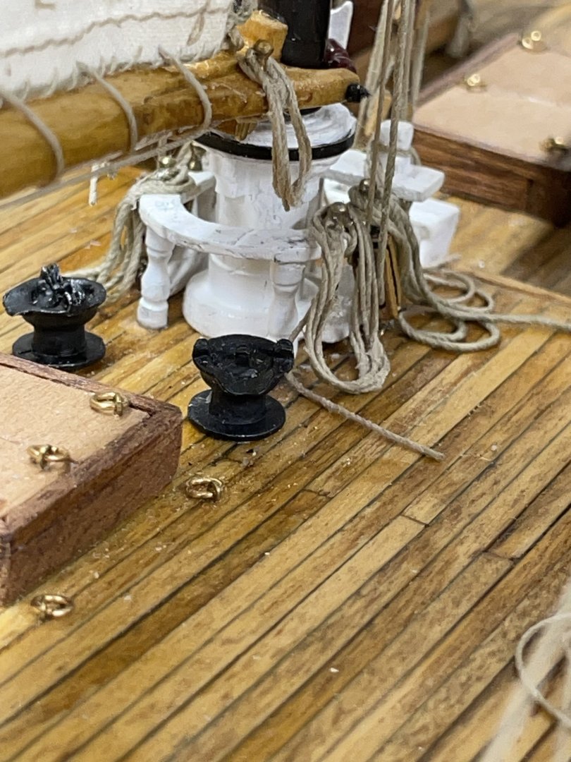
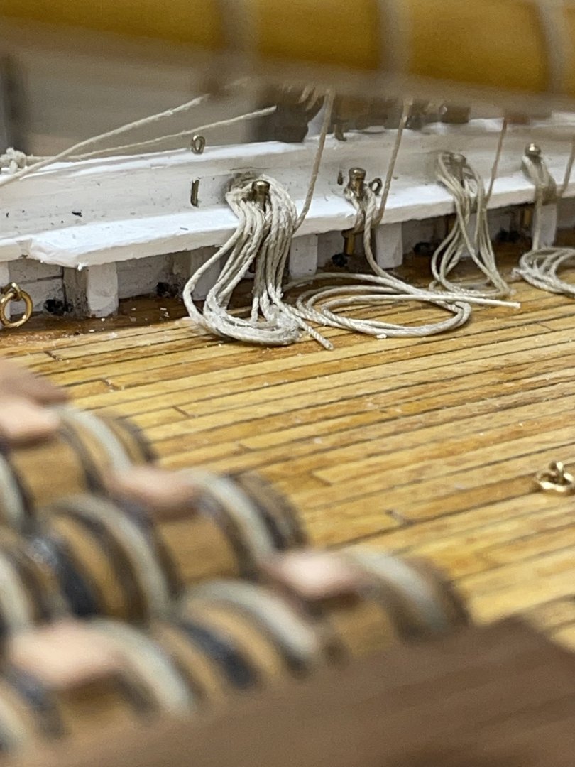
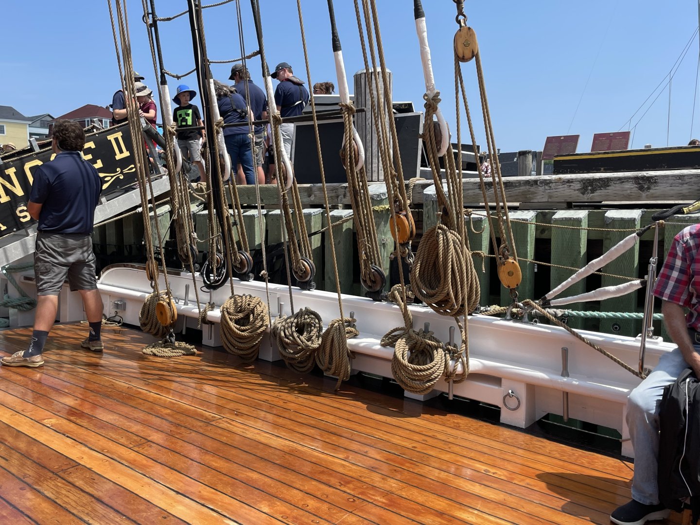
Note: In past builds I have rigged the lines and belayed them on the belaying pins, with sufficient extra line to loop them and tie them off as it is actually done on real ships. Those loops looked really good. Phil, stick with what works. Although rigging the loops the way you described is a pain in the a** the results are worth the effort. These photos show just how bad reality can look. (Photos taken aboard the Bluenose II this last summer in Nova Scotia.) I belay the rope as you described with extra line to coil. I then use Alene’s Tacky Glue for fabrics it dries clear and is somewhat flexible. Working quickly before the glue sets up I use tweezers and rigging tools to form the rope loops. Results on my 1921 Bluenose are shown in the photos below.
-
You are welcome, that’s what we are here for. Looks like you are sailing along now. Good job on that Bowsprit. 👏 John
- 207 replies
-
- vanguard models
- Duchess of Kingston
-
(and 1 more)
Tagged with:
-
I agree… In fact I know I will be rigging yards on the masts on my Red Jacket at 1/16” = 1’ 😆
- 207 replies
-
- vanguard models
- Duchess of Kingston
-
(and 1 more)
Tagged with:
-
Nice progress on the rigging there Bob. Cheers 🍻
- 207 replies
-
- vanguard models
- Duchess of Kingston
-
(and 1 more)
Tagged with:
-
Yes. I’m a bit confused 🤔 as well.
- 207 replies
-
- vanguard models
- Duchess of Kingston
-
(and 1 more)
Tagged with:
-
WOW 😮 She is really looking good. I love to see the sails going on, makes her come to life. Nice work, Phil. 🍻
-

Bluenose
John Ruy replied to Michael Kelly's topic in Building, Framing, Planking and plating a ships hull and deck
You may find my build log helpful. I covered planking fairly well. I found the Stern to be the most difficult part of planking the Bluenose. https://modelshipworld.com/topic/32549-1921-bluenose-by-john-ruy-finished-model-shipways-164-scale-canadian-fishing-schooner/ -
Bob, a am impressed you are so transparent, most of us would recover from our mistakes alone in our ship yard and post the results with no admission of the struggles. I for one appreciate and admire your tenacity. Nice work! 🍻
- 207 replies
-
- vanguard models
- Duchess of Kingston
-
(and 1 more)
Tagged with:
-
- 165 replies
-
- Red Jacket
- Marine Model Company
-
(and 2 more)
Tagged with:
-
Pictures look good, Bob 👍 If you want the masts to look straighter, just back up a bit and zoom in. That should give a bit less of a wide angle shot. If that doesn’t do it. You may need to realign your masts. Happy New Year 🍻
- 207 replies
-
- vanguard models
- Duchess of Kingston
-
(and 1 more)
Tagged with:
-
MERRY CHRISTMAS May you all have a Great Holiday and a blessed New Year. Cheers 🍻 PS… Been a bit busy with life this past three months. I’ll be back on here after the New Year..
- 165 replies
-
- Red Jacket
- Marine Model Company
-
(and 2 more)
Tagged with:
-
She’s coming along wonderfully, Bob. Nice work… Merry Christmas Cheers 🍻
- 207 replies
-
- vanguard models
- Duchess of Kingston
-
(and 1 more)
Tagged with:
About us
Modelshipworld - Advancing Ship Modeling through Research
SSL Secured
Your security is important for us so this Website is SSL-Secured
NRG Mailing Address
Nautical Research Guild
237 South Lincoln Street
Westmont IL, 60559-1917
Model Ship World ® and the MSW logo are Registered Trademarks, and belong to the Nautical Research Guild (United States Patent and Trademark Office: No. 6,929,264 & No. 6,929,274, registered Dec. 20, 2022)
Helpful Links
About the NRG
If you enjoy building ship models that are historically accurate as well as beautiful, then The Nautical Research Guild (NRG) is just right for you.
The Guild is a non-profit educational organization whose mission is to “Advance Ship Modeling Through Research”. We provide support to our members in their efforts to raise the quality of their model ships.
The Nautical Research Guild has published our world-renowned quarterly magazine, The Nautical Research Journal, since 1955. The pages of the Journal are full of articles by accomplished ship modelers who show you how they create those exquisite details on their models, and by maritime historians who show you the correct details to build. The Journal is available in both print and digital editions. Go to the NRG web site (www.thenrg.org) to download a complimentary digital copy of the Journal. The NRG also publishes plan sets, books and compilations of back issues of the Journal and the former Ships in Scale and Model Ship Builder magazines.

