


jdbondy
-
Posts
299 -
Joined
-
Last visited
Content Type
Profiles
Forums
Gallery
Events
Posts posted by jdbondy
-
-
Congratulations, Matiz!
- mtaylor and Keith Black
-
 2
2
-
-
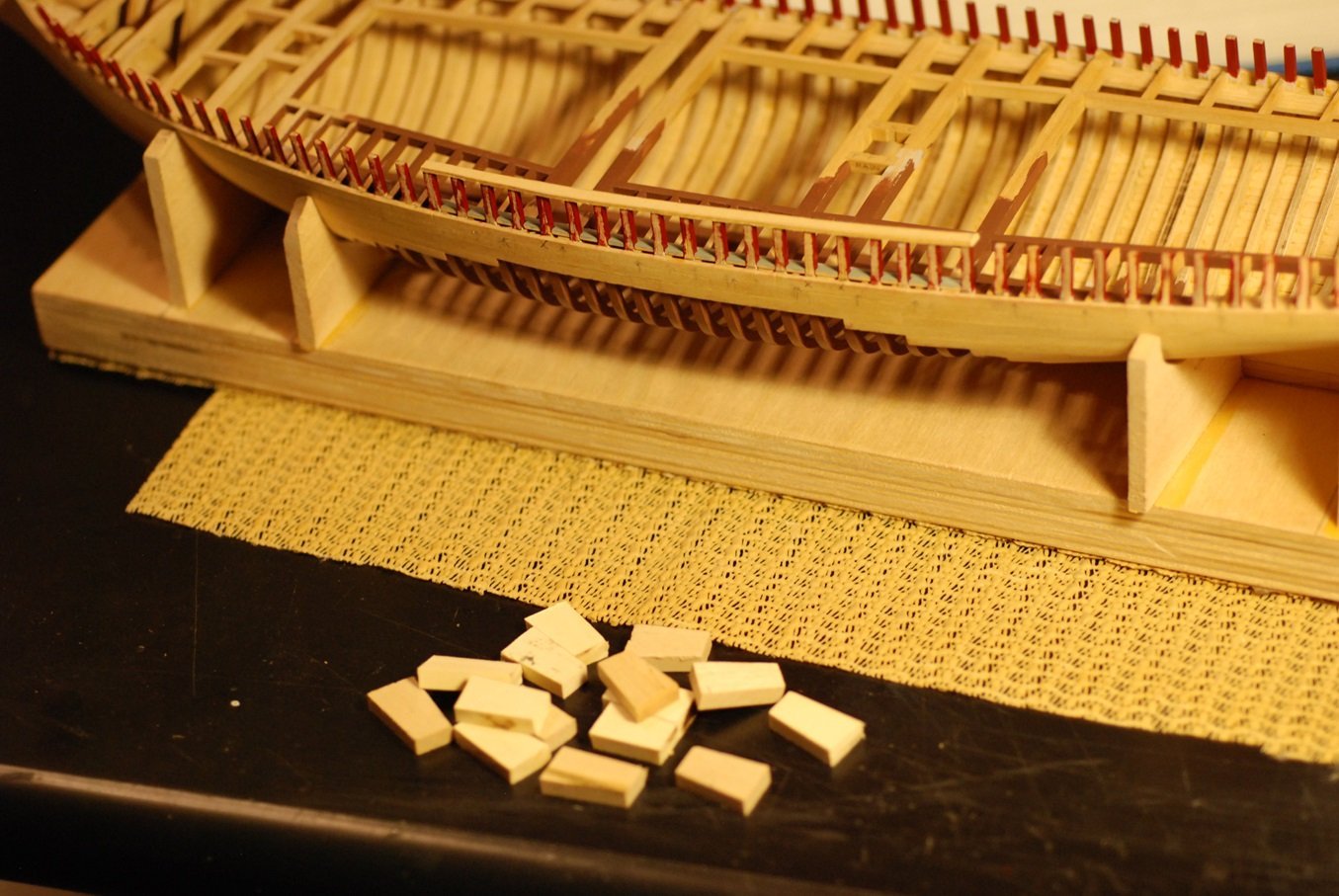
Thanks everyone! All six covering board pieces have now been installed and now I am trimming away the excess wood from each piece in anticipation of installing the margin plank for the decking. I hope to post a brief update soon. And I hope that after having finished this task, things will accelerate appreciably.
- Keith Black, davec, mtaylor and 1 other
-
4
-
Most of us model buidlers know that the covering boards are the pieces of timber that cover the hull-deck joint structure. Chances are you know that they are very complicated things to build. This step of the build simply confirmed that.
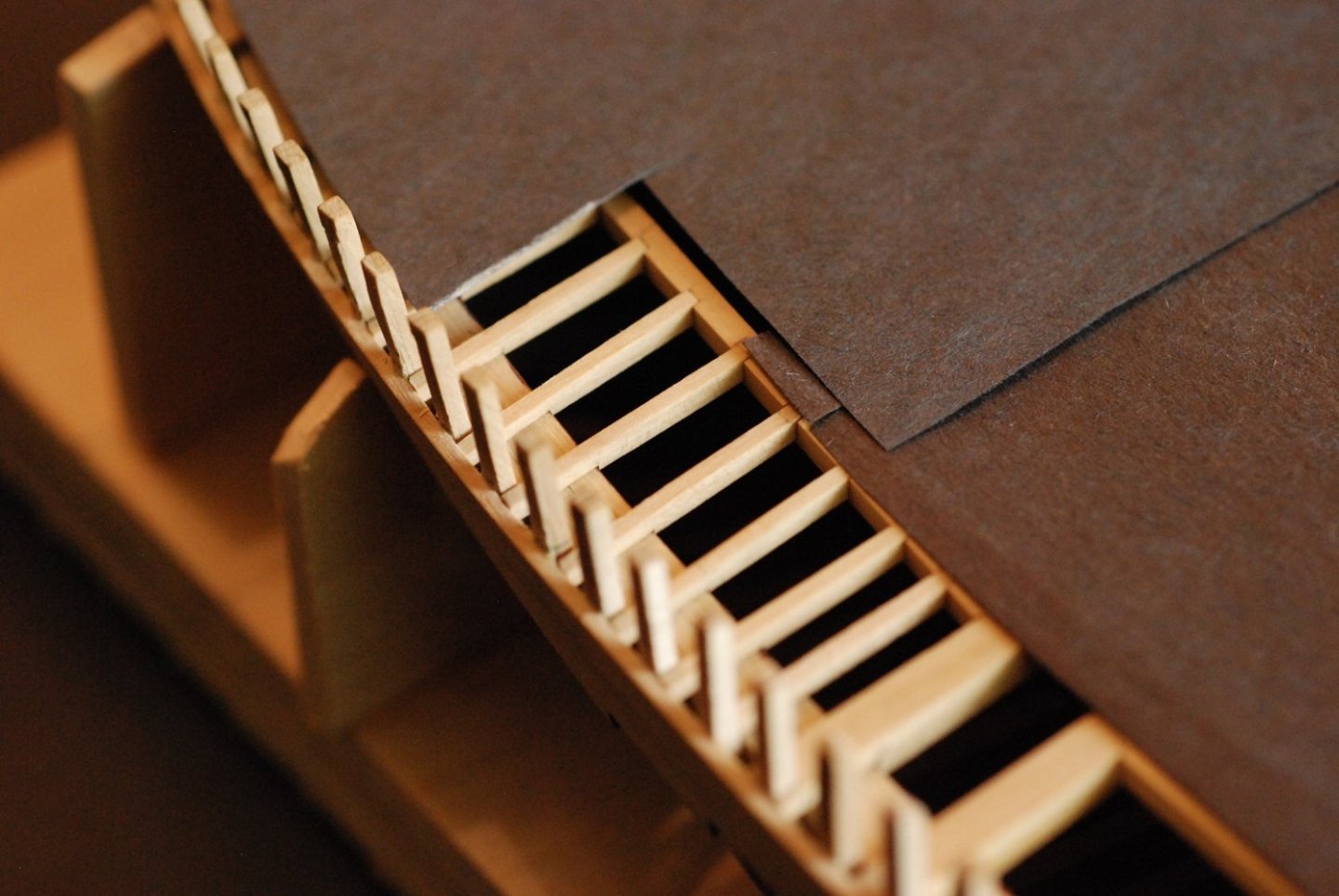
Covering boards usually are solid pieces of wood that are penetrated by holes that accommodate the stanchions that must travel through them. For me to produce them like that would have simply been impossible. These will be complicated enough to build as is. Essentially, I will fabricate the inboard side of the covering boards with “teeth” that project between the stanchions, then the outboard edge will be added in a separate step. The seam between the two pieces should be effectively hidden in the alcove formed by the stanchions and the bulwarks planking.
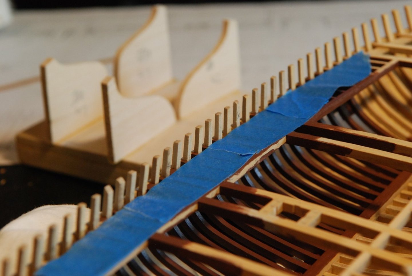
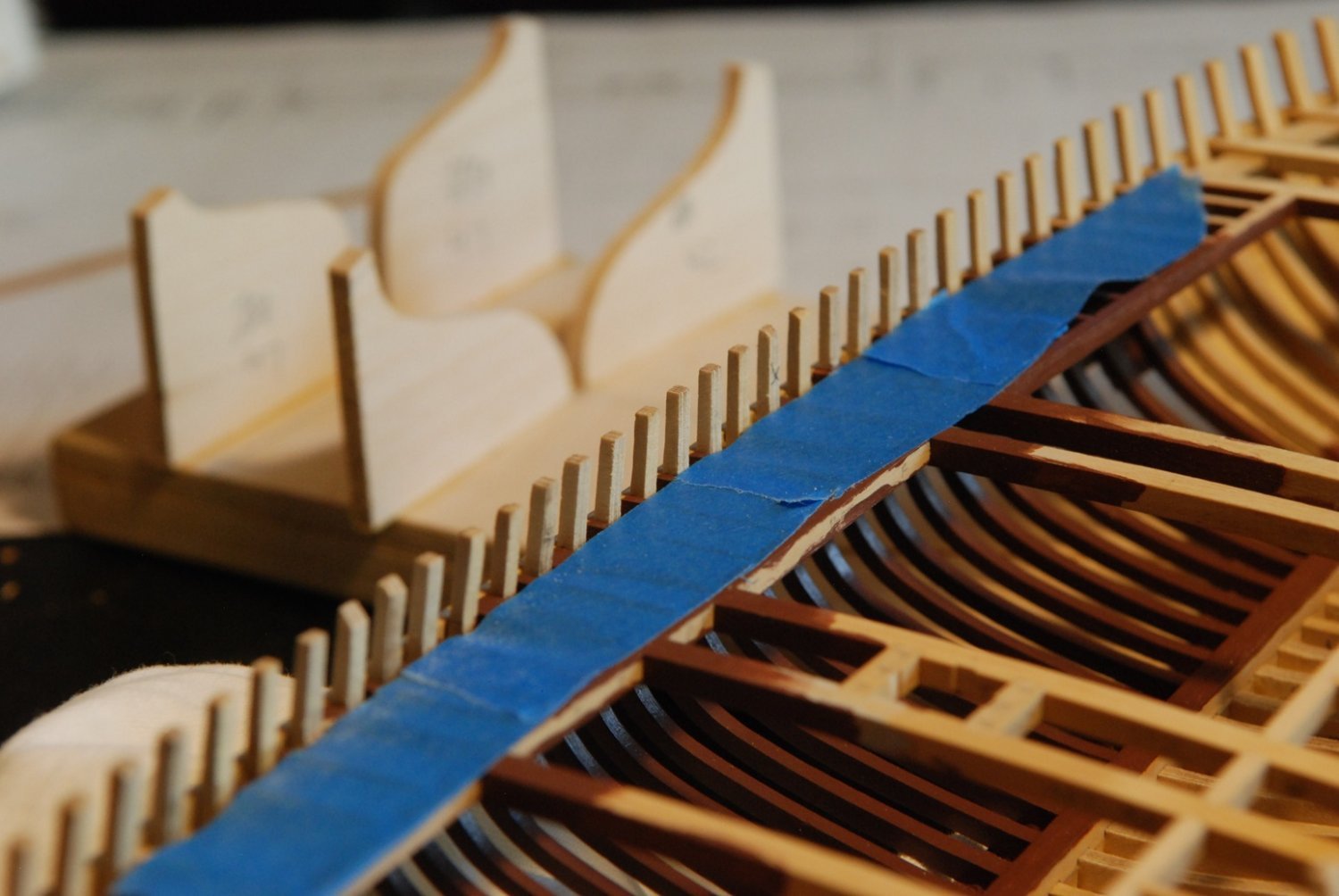
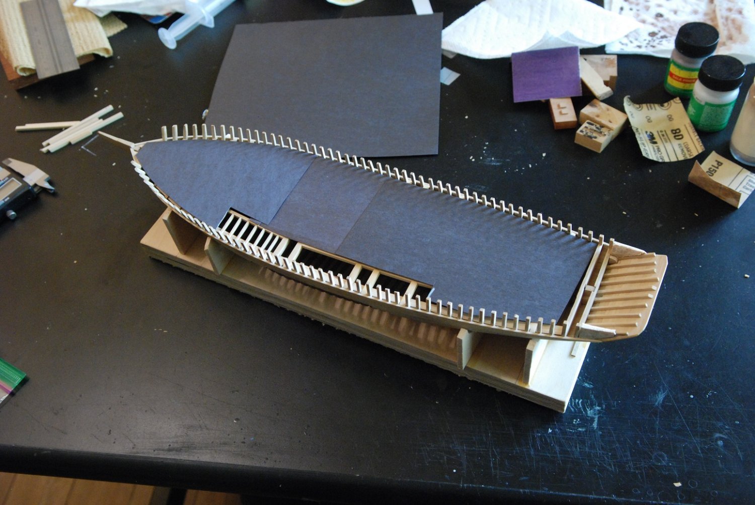
Here I have covered the deck structure adjacent to the stanchions with tape because I was wishing to protect my paint job of the deck structure that would remain visible in an unplanked area of deck. The protection was needed because I knew I would need to fair down the ledges to the level of the sheer in order for the covering boards to fit, and I didn’t want to harm the paint job.
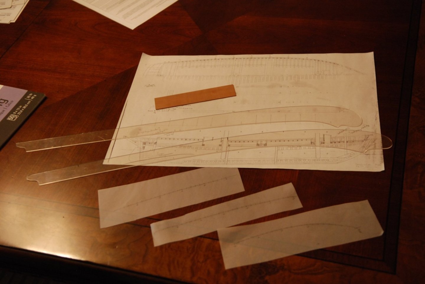
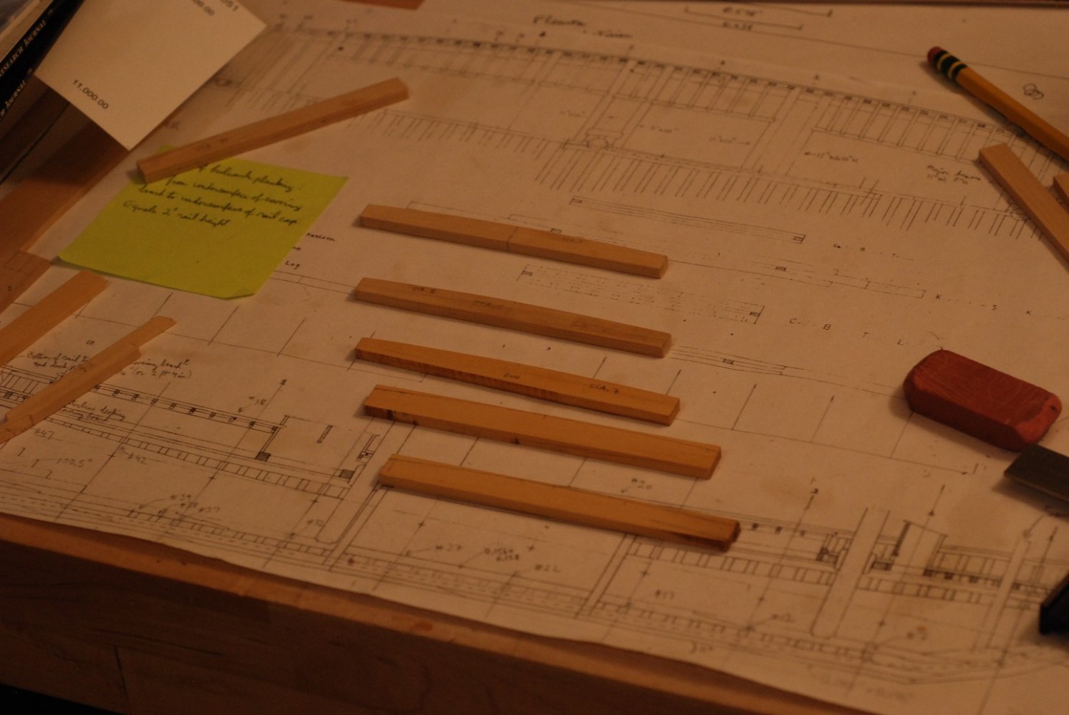
In order to start the process, I needed to obtain the shape of the sheer from the plans. These were transferred using tracing paper to 3/64” stock. These shapes were then cut out excessively wide.
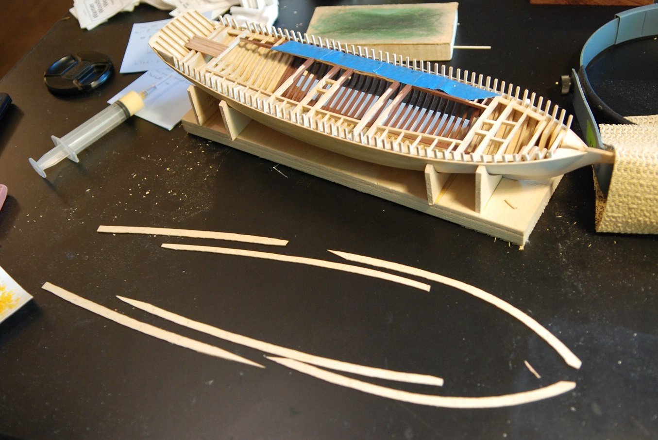
This results in six overly-wide and overly-long pieces, with generous areas of overlap.
Using double-sided tape, an individual piece was tacked down to the level of the deck structure. The forward and aft edges of each stanchion were marked, keeping track of station locations.
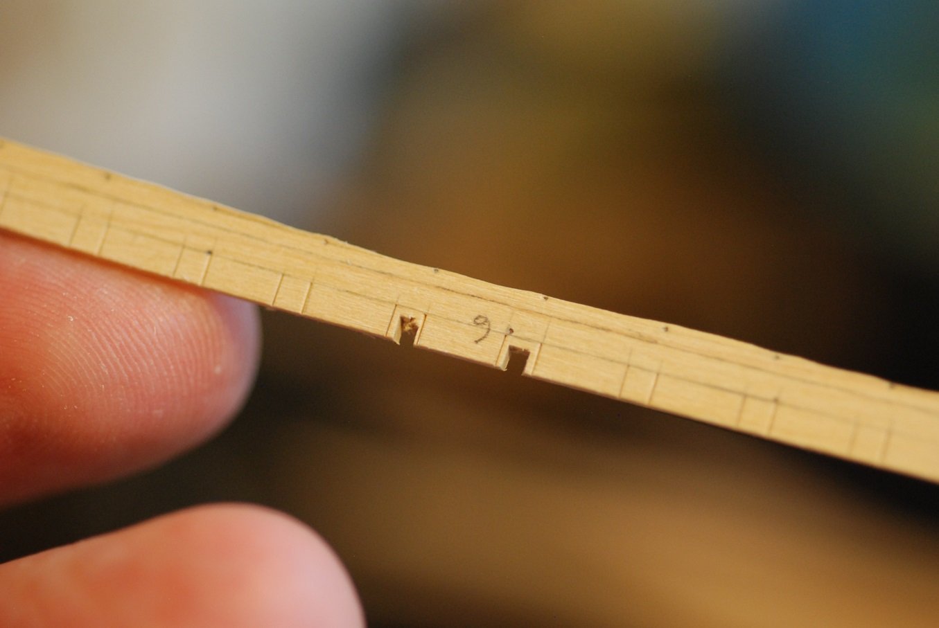
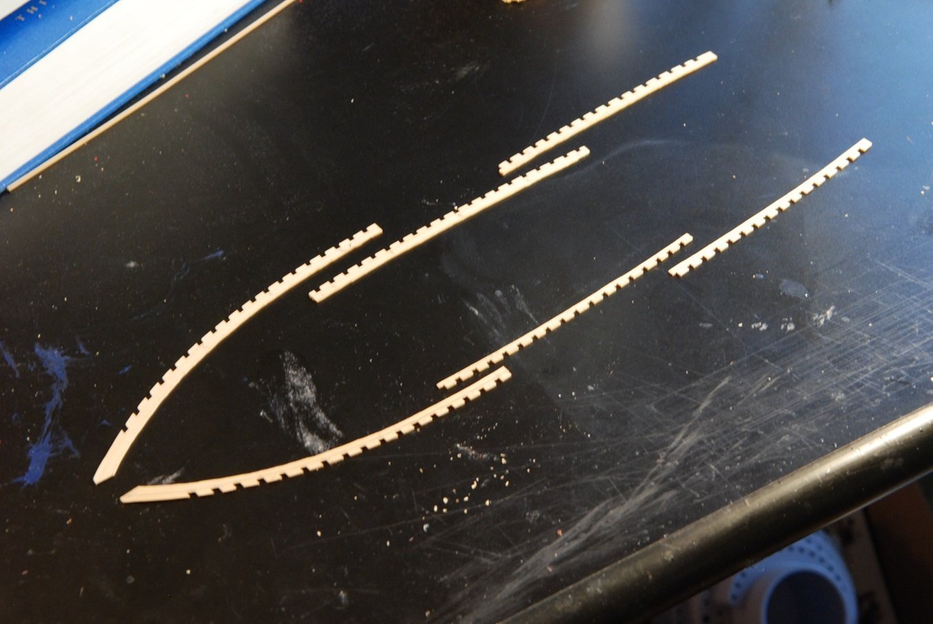
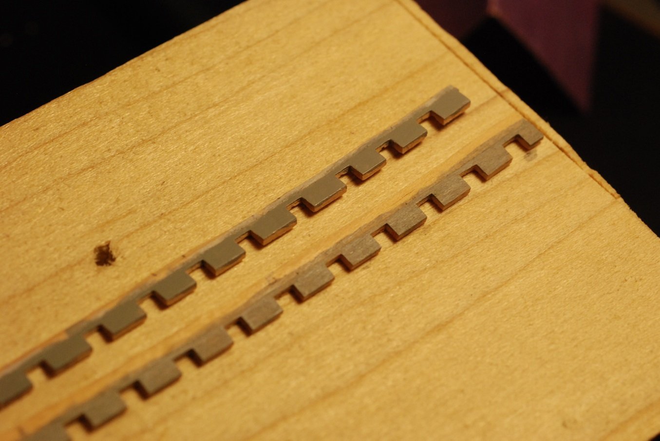
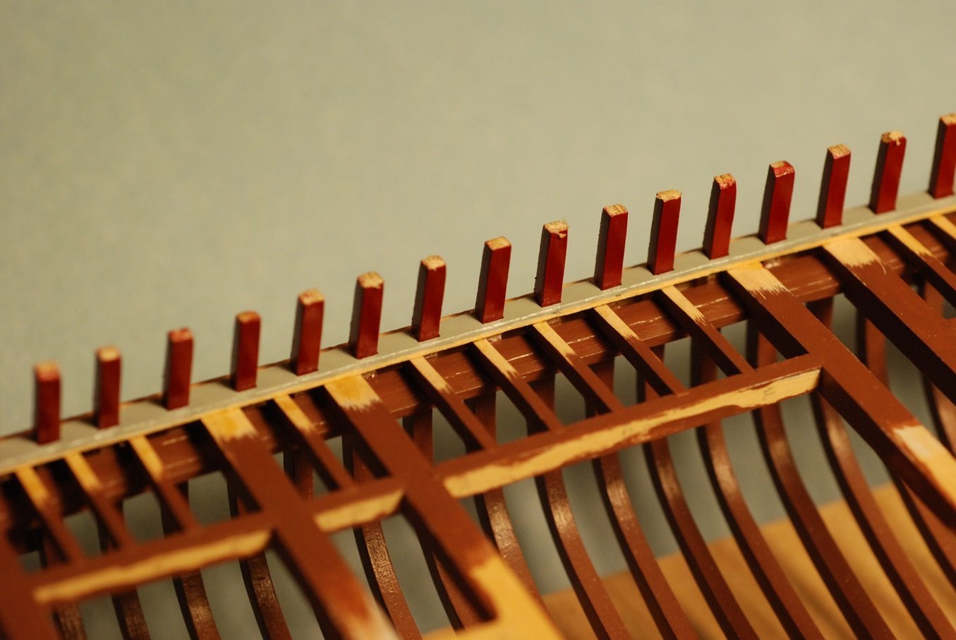
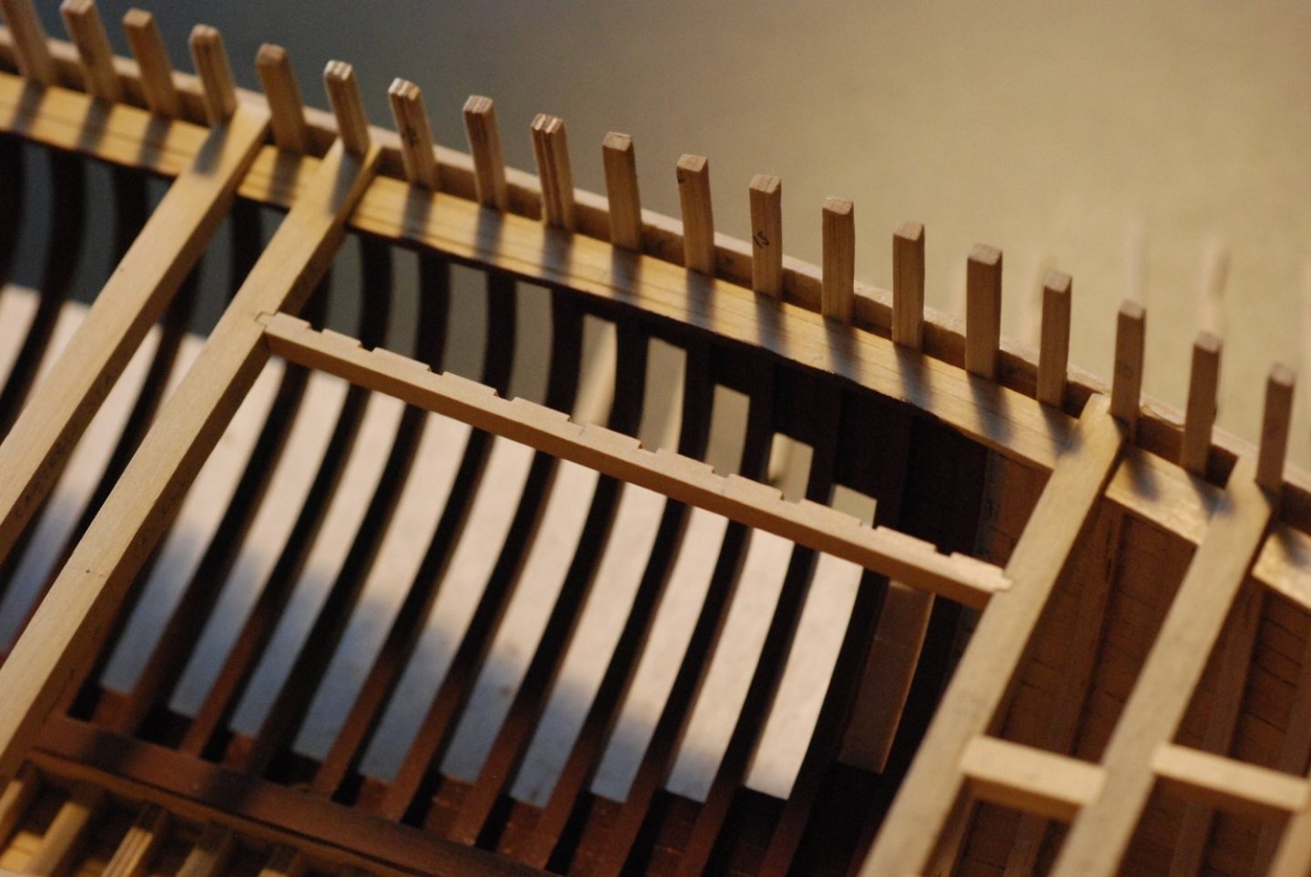
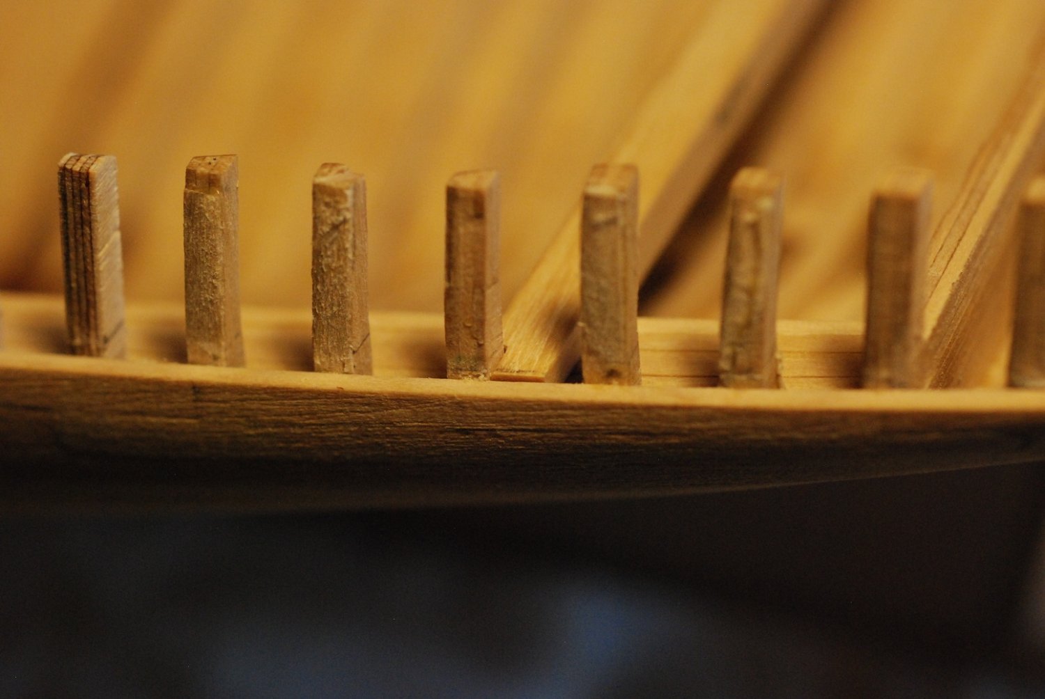
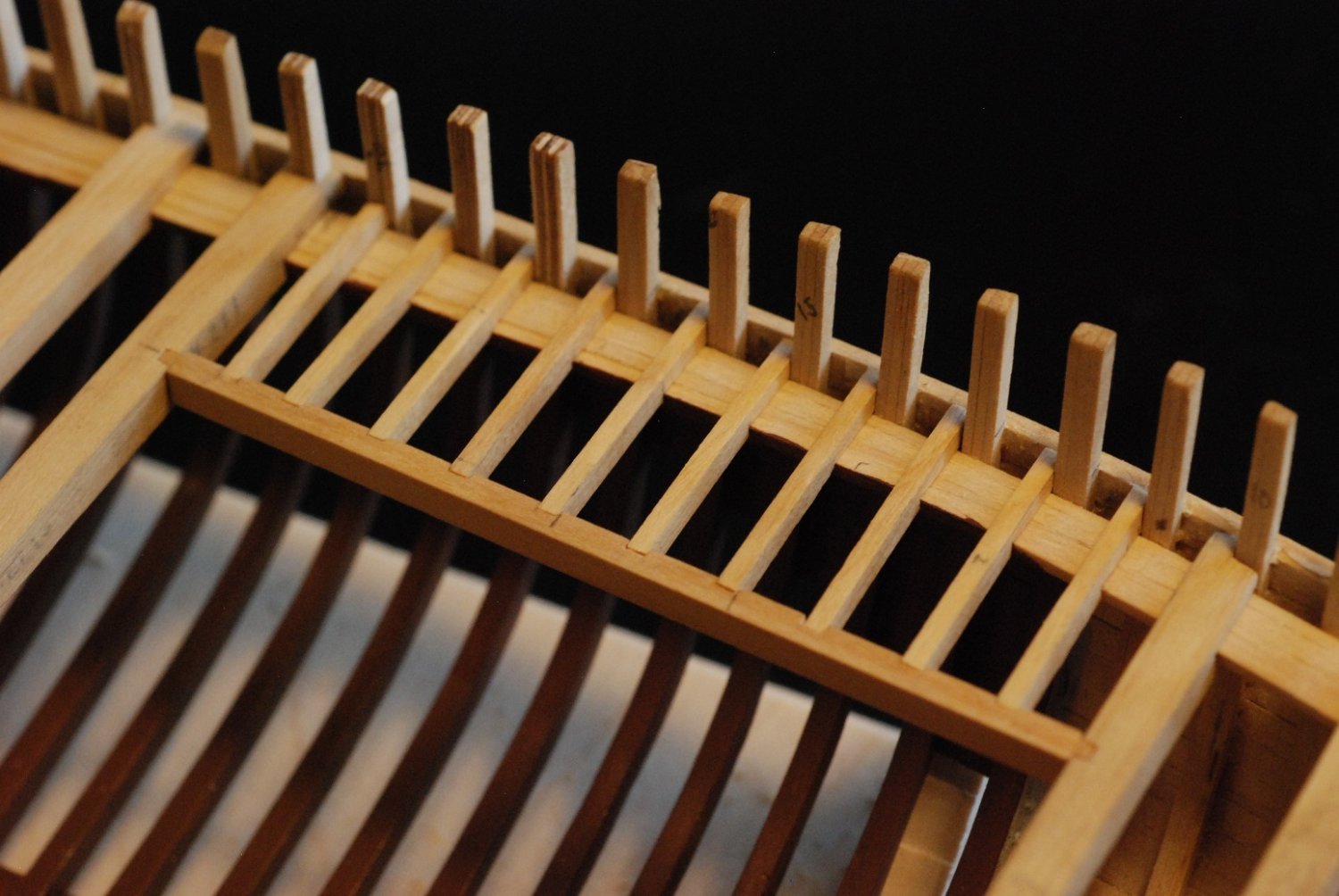
Now the really slow part began. Under the microscope, I began cutting out notches to make the “teeth” that will extend between each stanchion. Again, each covering board piece was made so that its inboard edge was continuous. The outboard edge of the covering board will be added as a separate piece later on in the build.
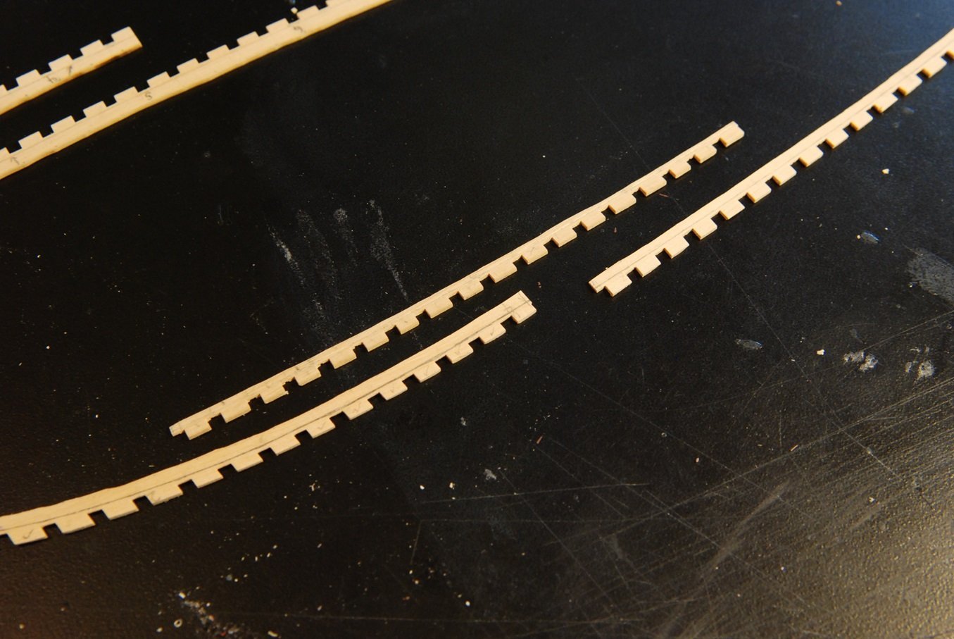
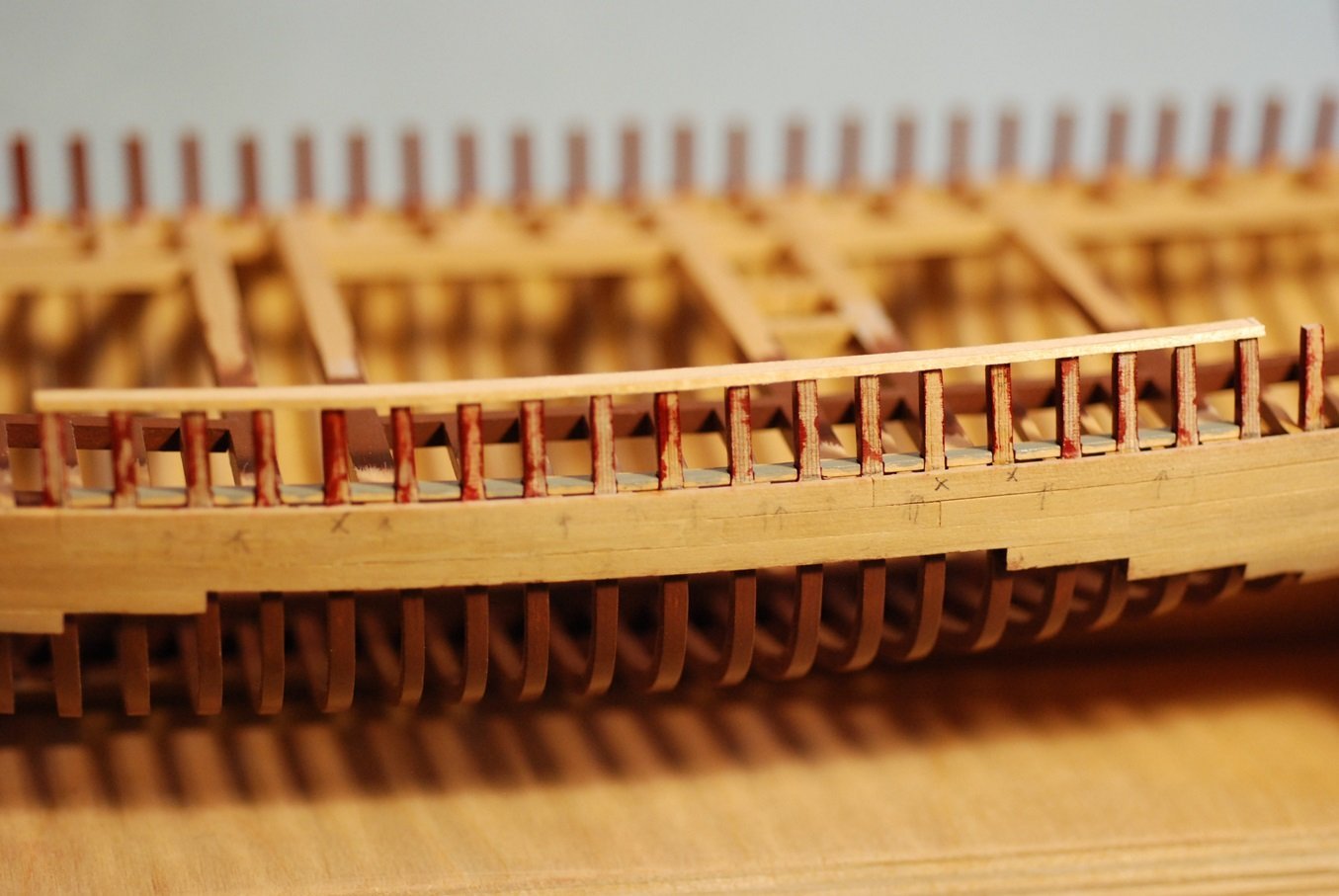
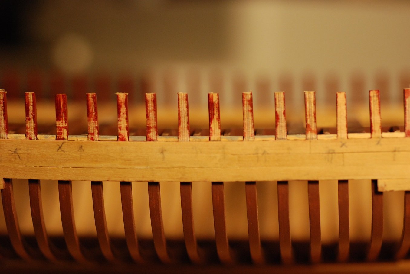
This piece shows many of the notches at full width, while others are still being widened. The width of each stanchion was relatively standard, but the gaps between the stanchions varied just enough to require extensive trial and error fittings.
But wait, that’s not all. Once all of the notches are wide enough, now they each need to be made deep enough. And none were of exactly of the same depth, due to individual differences in the shapes and angles of the stanchions. This again required many trial and error fittings with the goal of leaving minimal gap between the covering board’s notch and the inboard surface of each stanchion.
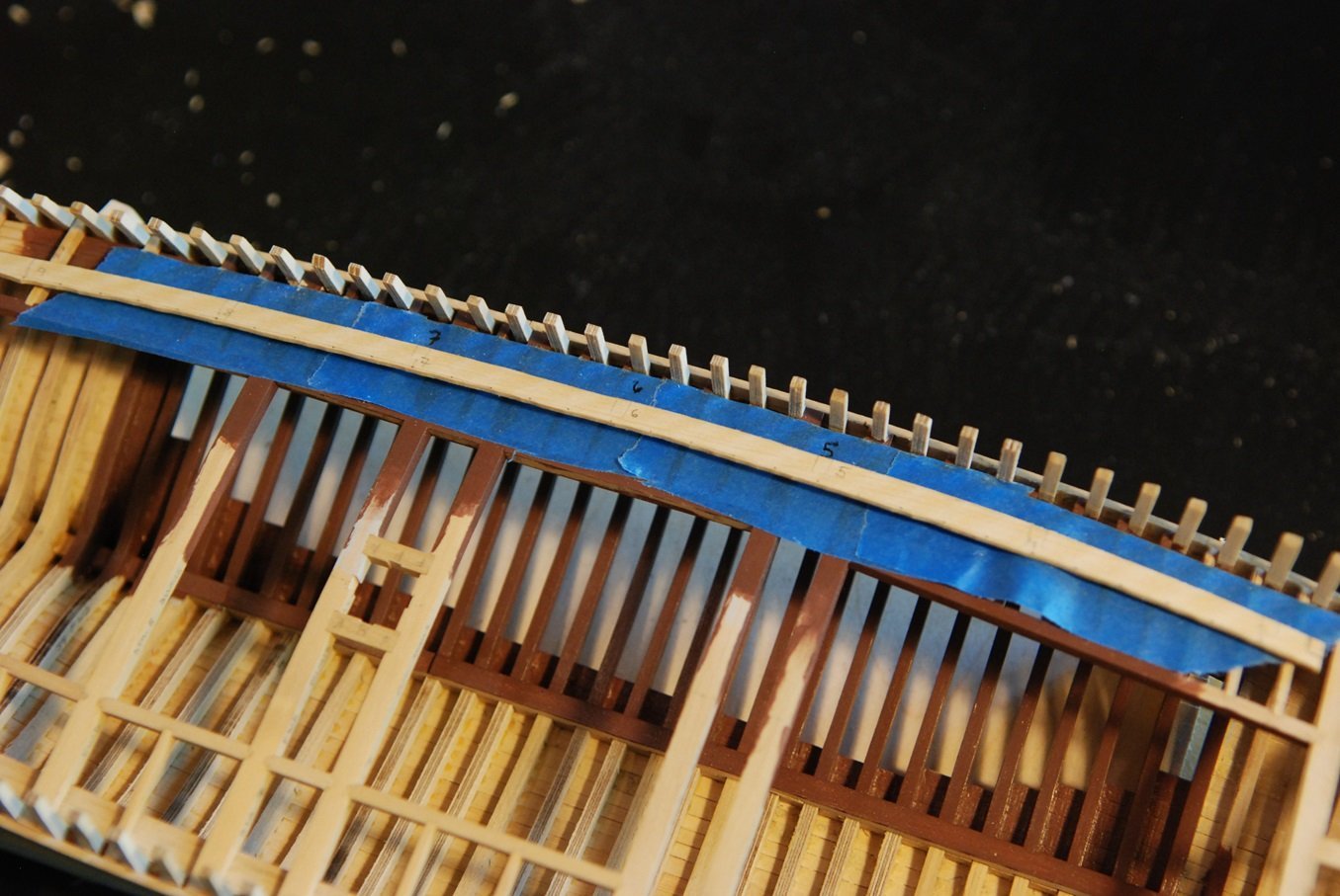
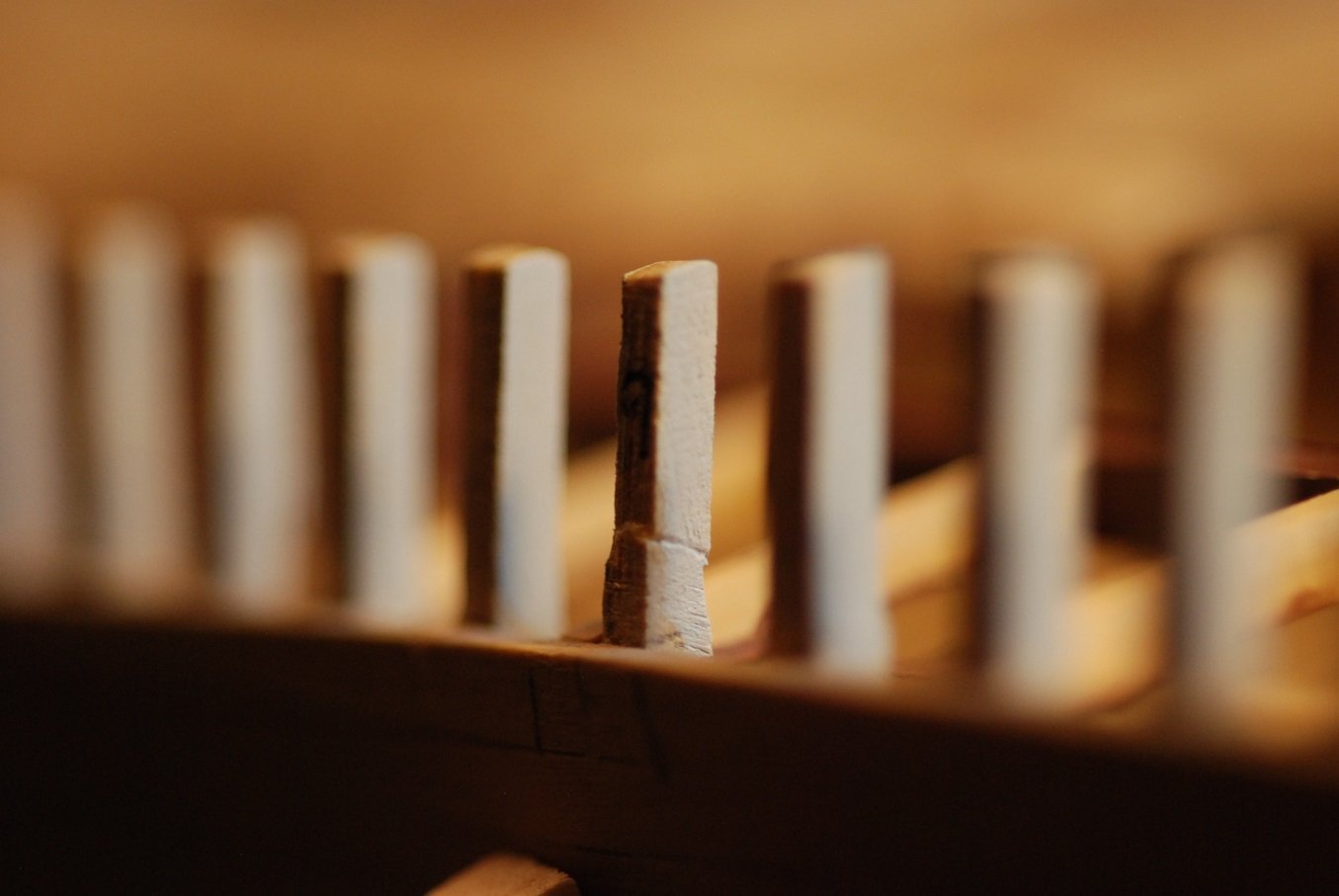
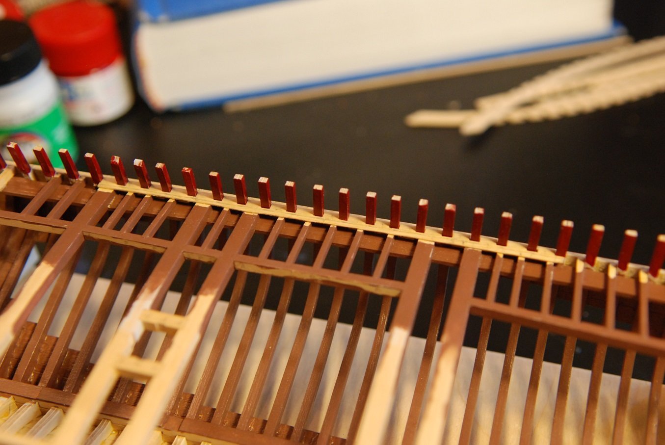
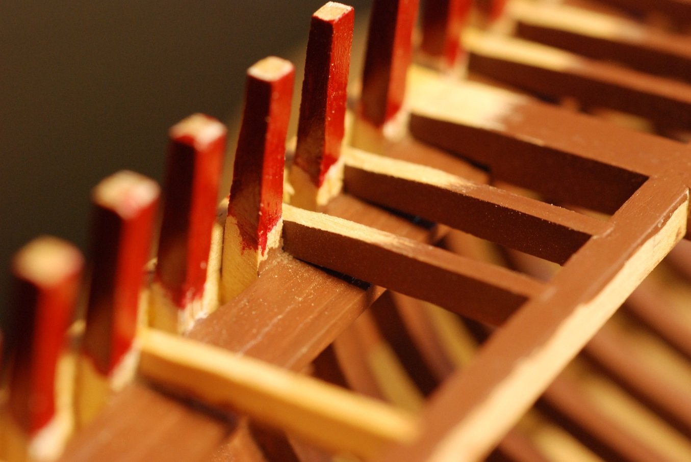
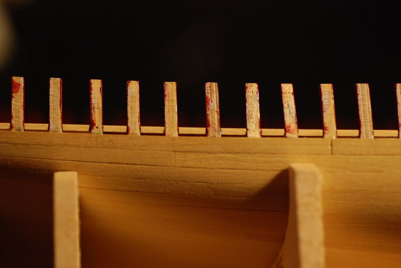
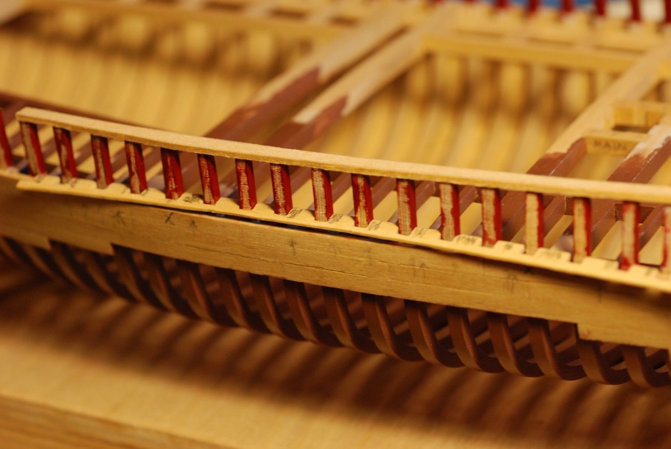
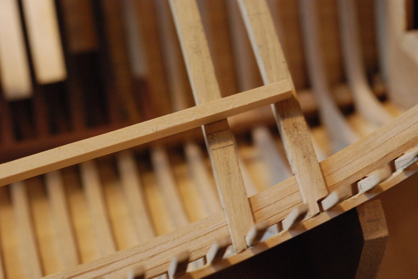
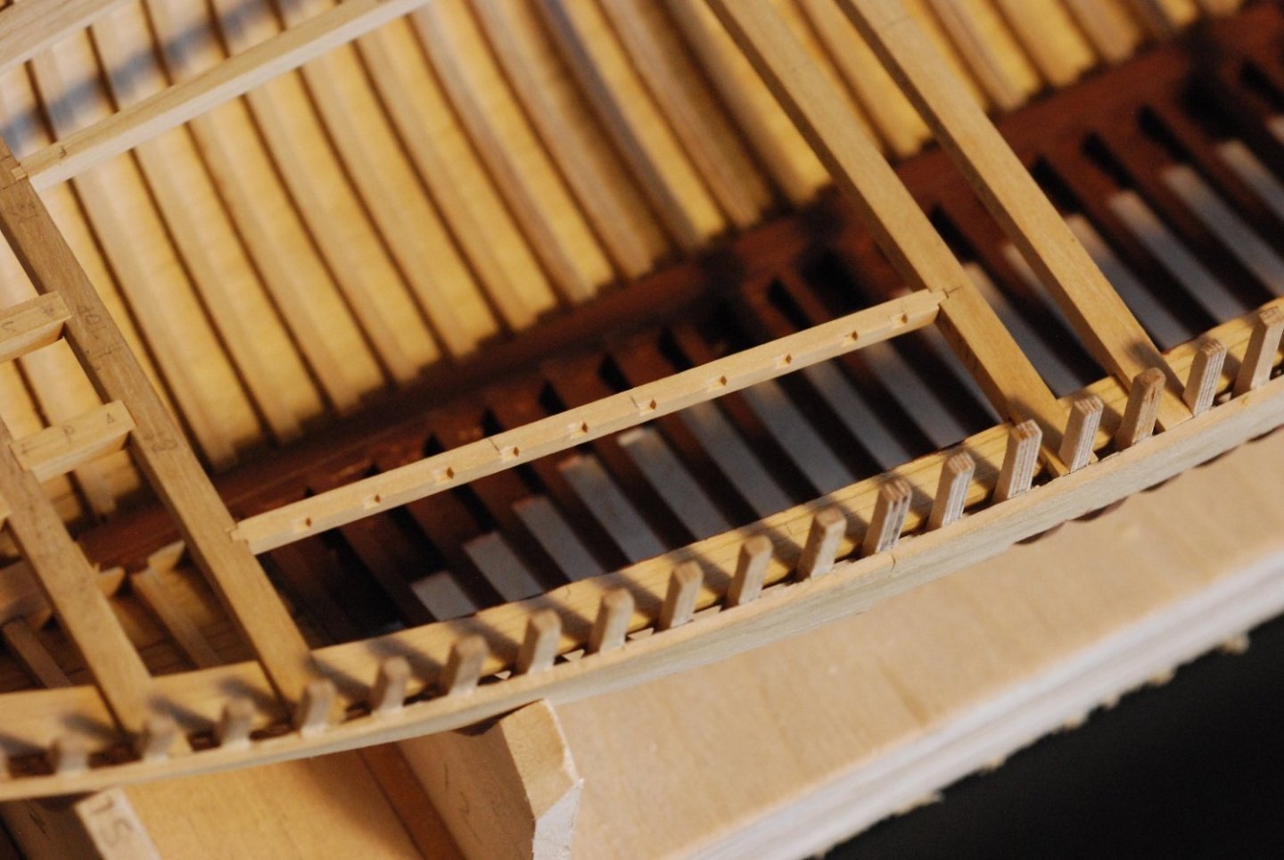
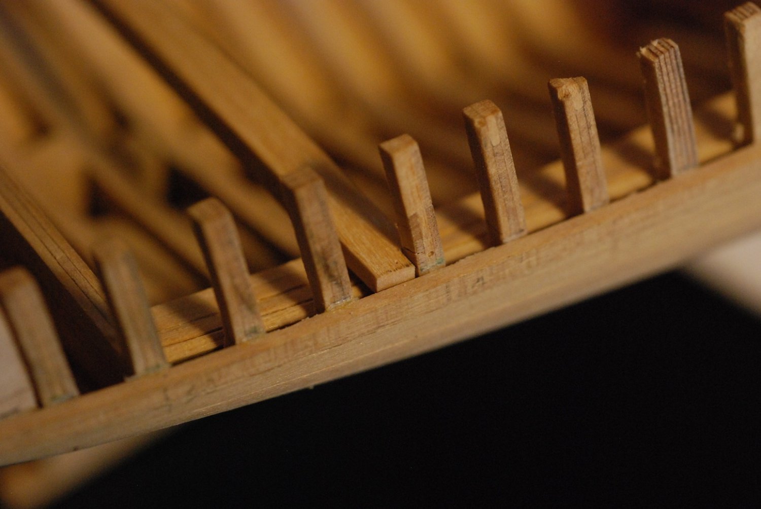
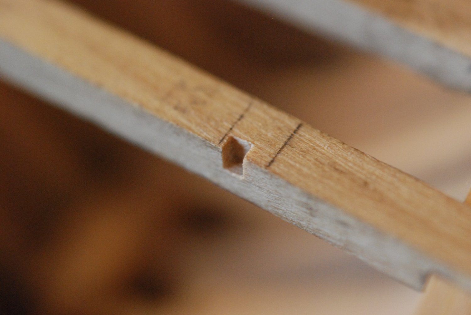
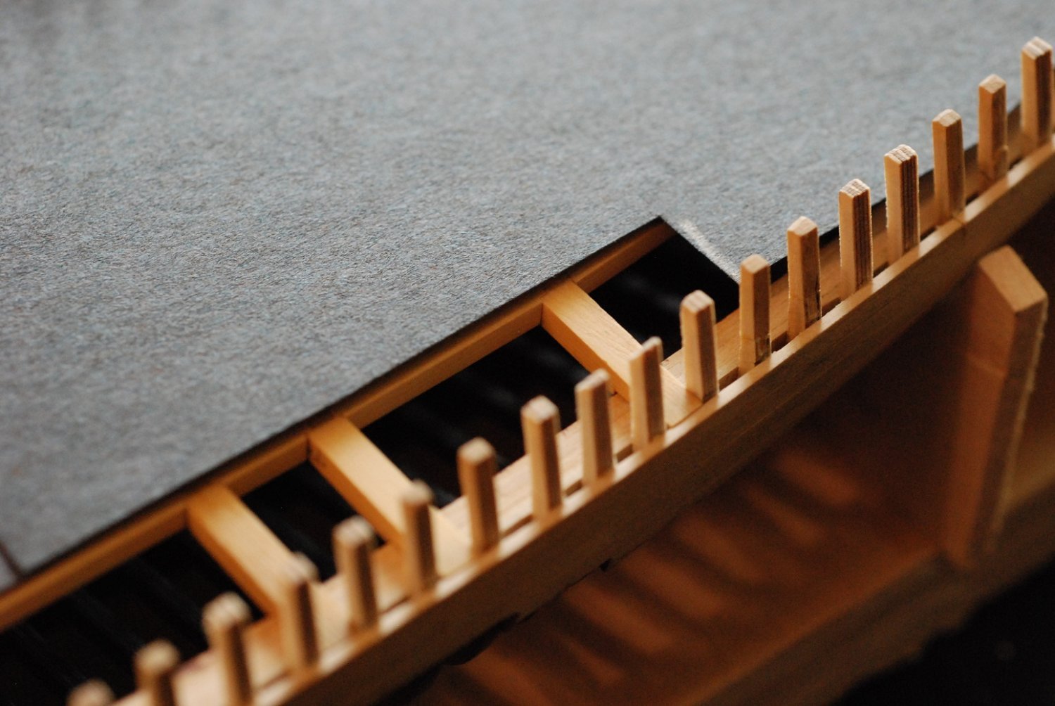
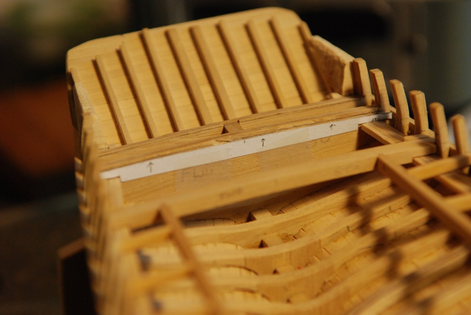
In the real ship, there is only about a 2 inch gap between the inboard surface of the stanchions and the margin plank of the deck. This is 1/32” in model scale. You can see the anticipated final inner edge of the covering board marked with a continuous pencil line here.
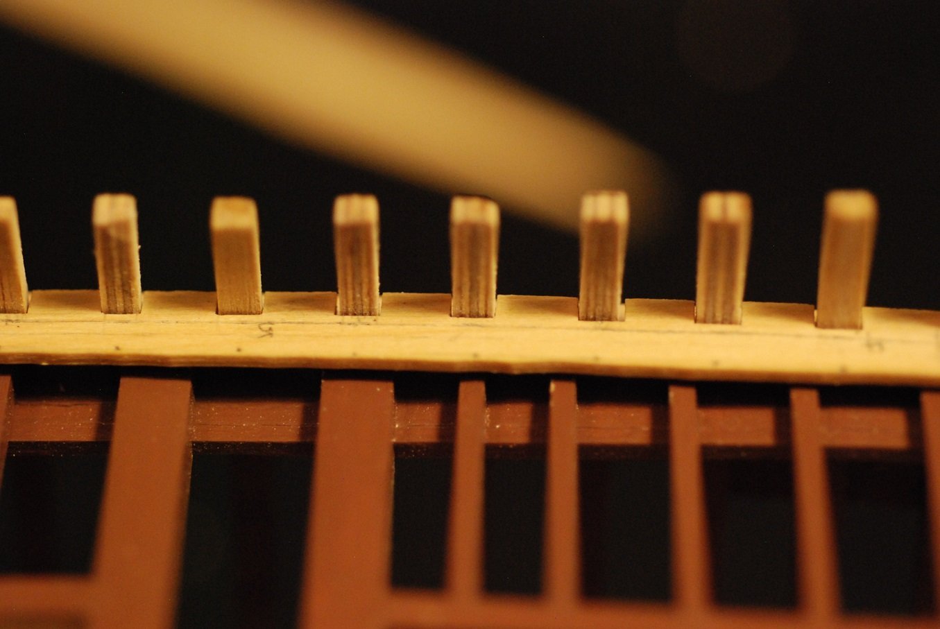
Perhaps it is a little more clear in this image. At this point there is a lot of excess wood on the inboard edge of the covering board. Removal of this excess will have to wait until later, as trimming it all off at this time would leave a piece of wood that is impossibly fragile.
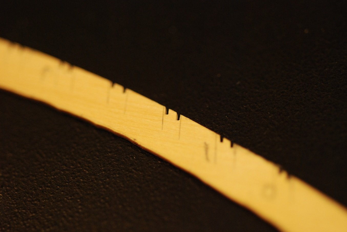
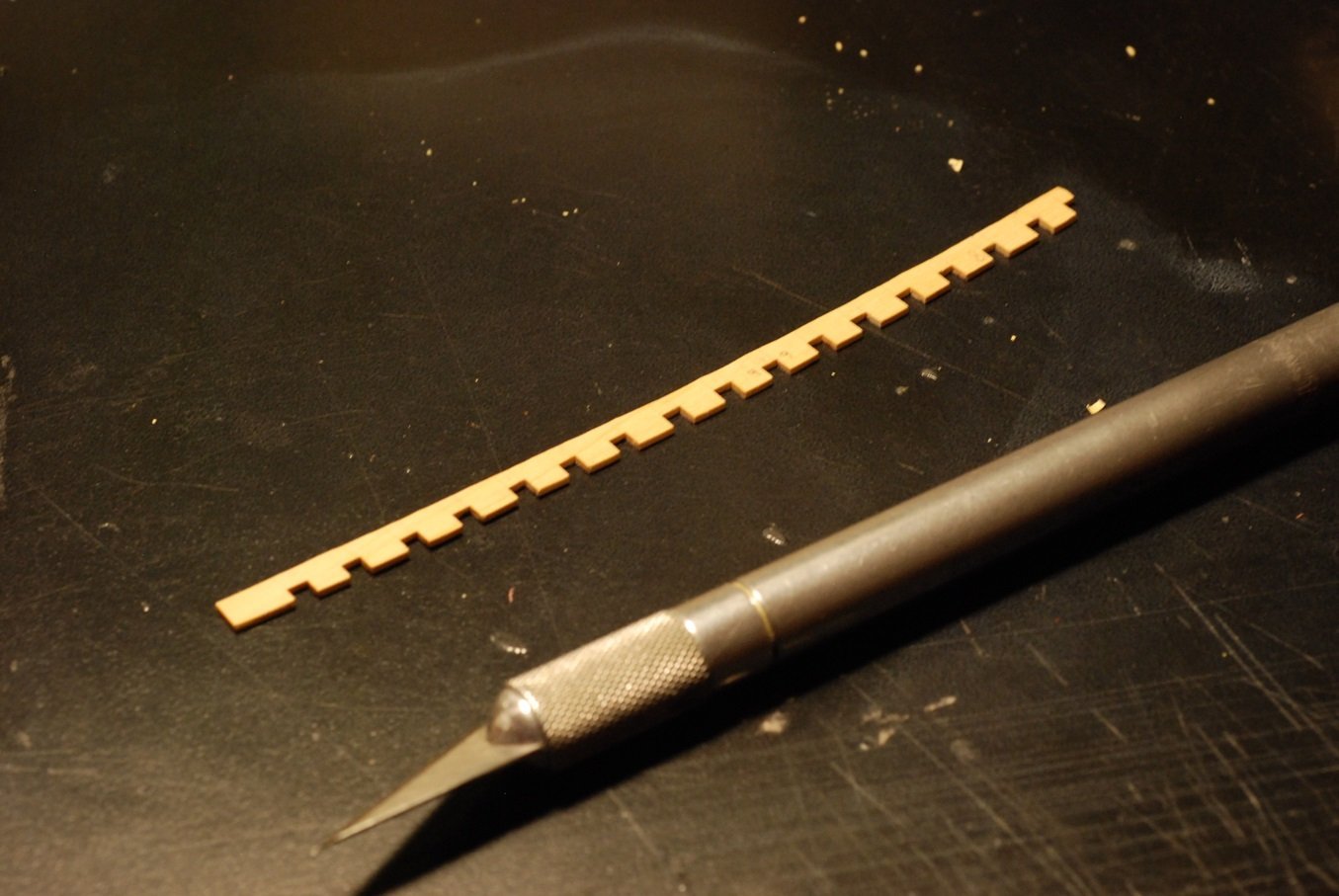
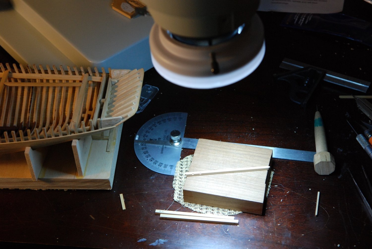
The process of cutting the notches was accelerated when I realized I could use my table saw and miter to at least start the notches in a more efficient manner.
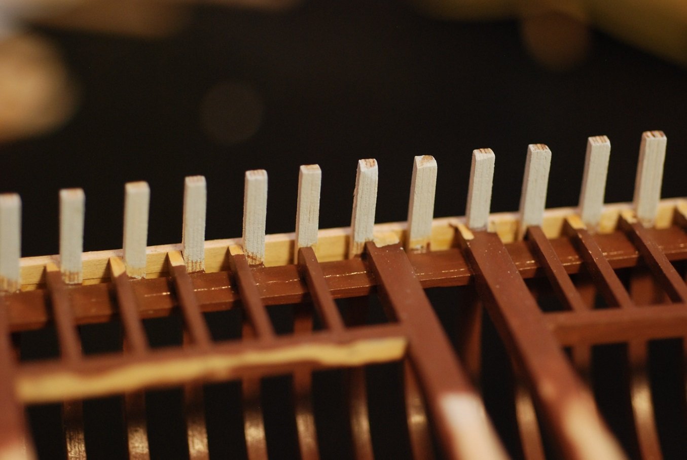
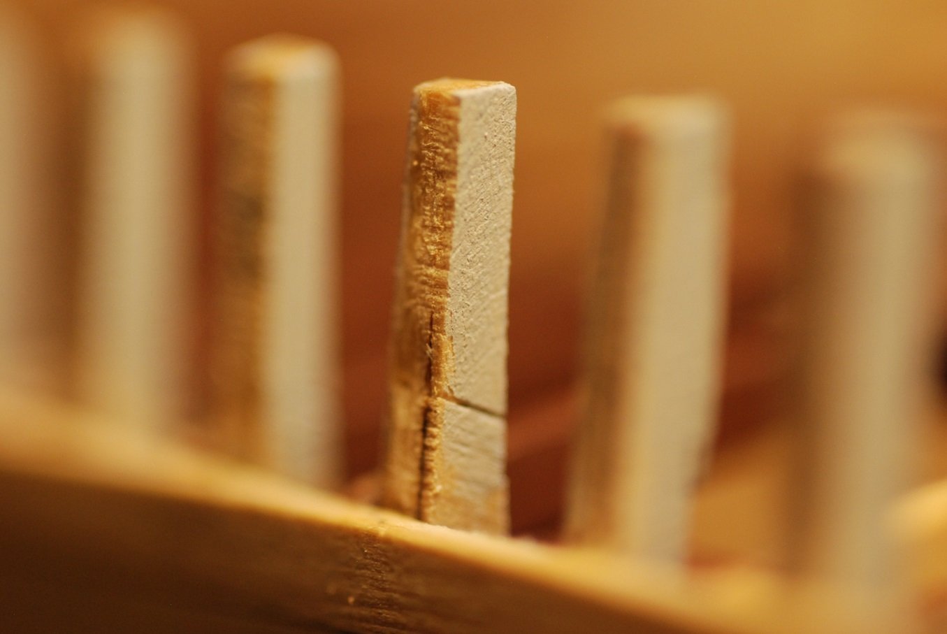
After having cut the notches to proper spacing, width, and depth, it was time to prep and paint the stanchions. Paint would add just enough thickness to each surface of the stanchions to require further tuning of the notches.
For primer, I used some old Badger Model-Flex gray, which had thickened considerably. It was diluted with water to a usable thickness, but it still maintained enough body to serve as an effective filler.
Overall this achieved a pretty smooth surface, but some defects were hard to fill completely, even after using primer and model filler.
I can’t remember how long it took to make all of these very bespoke pieces, but keep in mind that my last proper post was back in July…
There is lots of overlap, way more than I really needed, which also slowed the process.
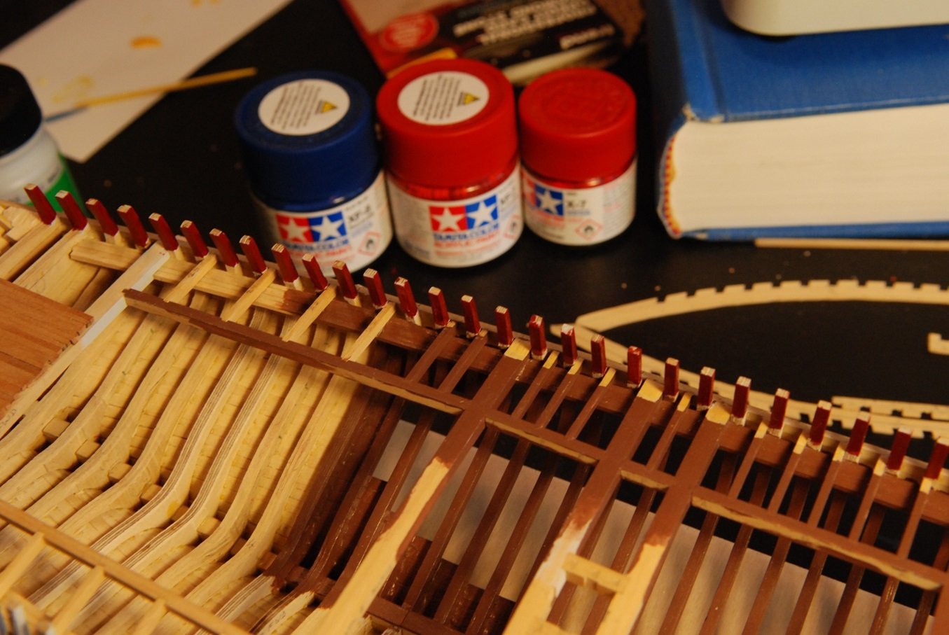
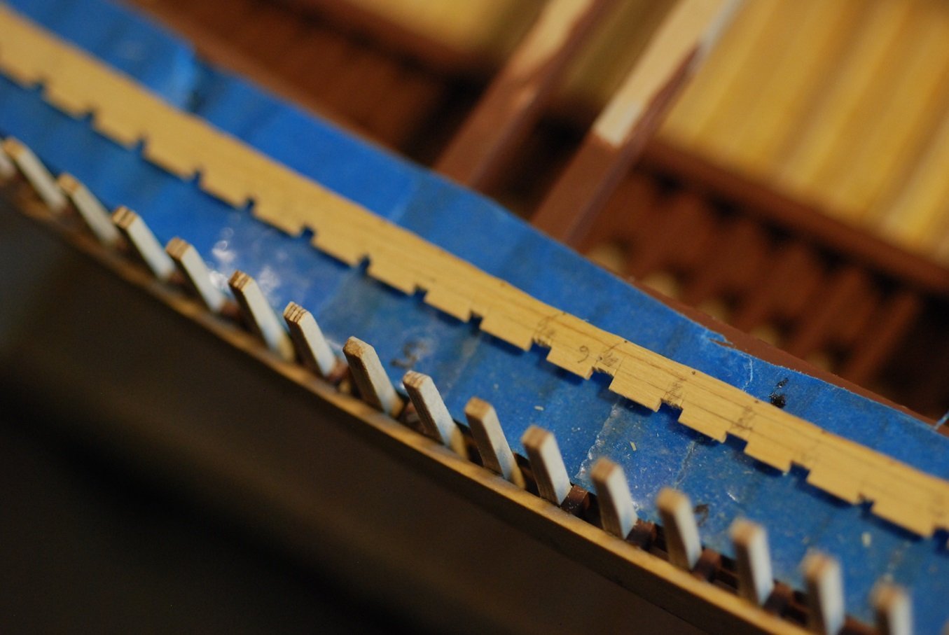
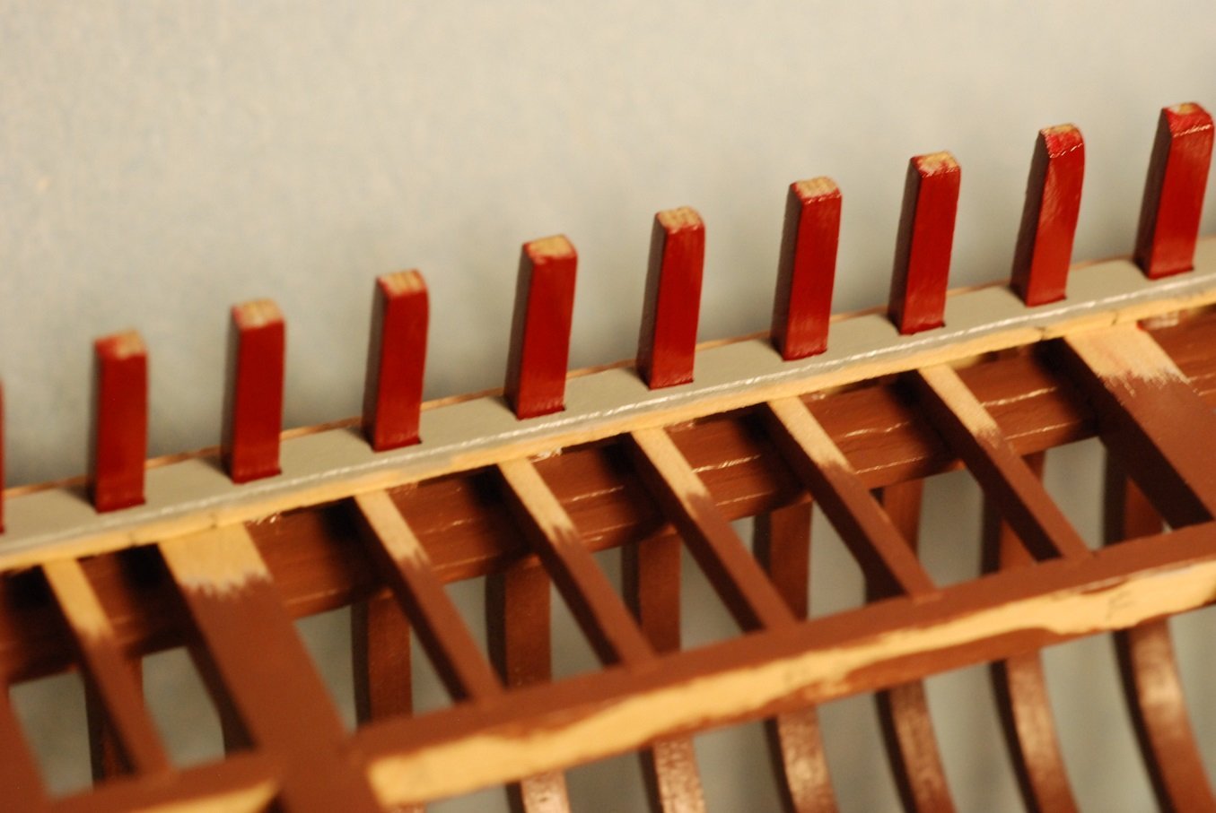
The stanchions and the inboard surfaces of the bulwarks planking are a burgundy color. I slowly added drops of blue Tamiya paint into a small jar of Tamiya red to achieve the desired shade of burgundy. The one small jar may in the end not be enough, because I will also use it to paint the inboard surfaces of the bulwarks planking. It took 3-4 coats to get a good smooth surface.
And as already mentioned, the notches had to be tuned again after painting the stanchions was finished.
So despite my efforts to protect them, I had to scrape and sand away portions of the previously painted deck structure. In fact, re-shaping of the deck beams and ledges was necessary in order to get the covering boards to sit flush with the sheer.
This ledge shows considerable downsloping toward the sheerline to accommodate the shape of the covering board.
So there will need to be repainting of the deck structure that will remain visible, after all.
The deck beams and ledges also required re-fairing of their curve once I had removed enough material to accommodate the covering board.
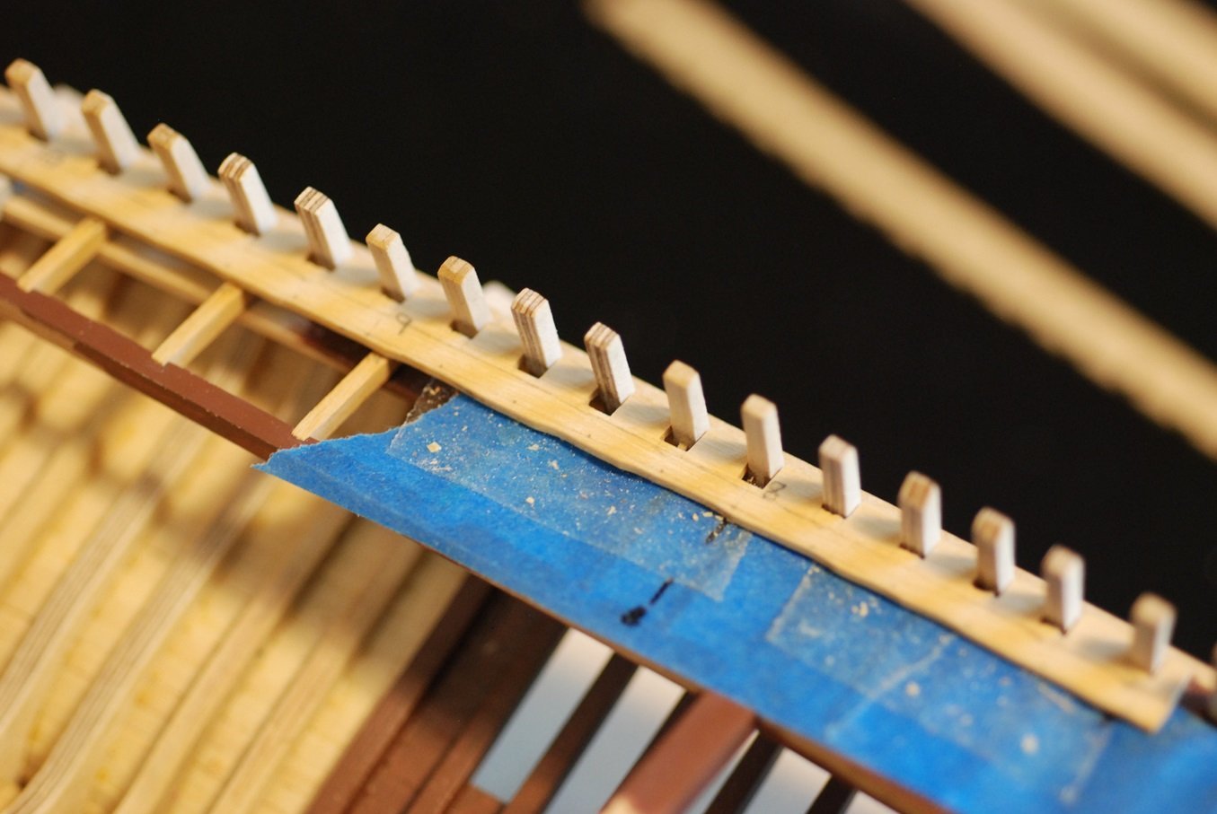
The covering boards were painted with a medium gray. Excess paint that ended up in the notches had to be sanded away after this was done.
At this point, I used the X-acto blade to begin removing some of the excess wood from the inboard edge of the covering boards. This helped make it easier to tune the pieces to sit against their underlying deck beams and ledges. It was also necessary to shape the undersurface of the covering boards to accommodate the camber of the deck structure. I carefully sanded the undersurface to change the cross section from rectangular to an angular undersurface.
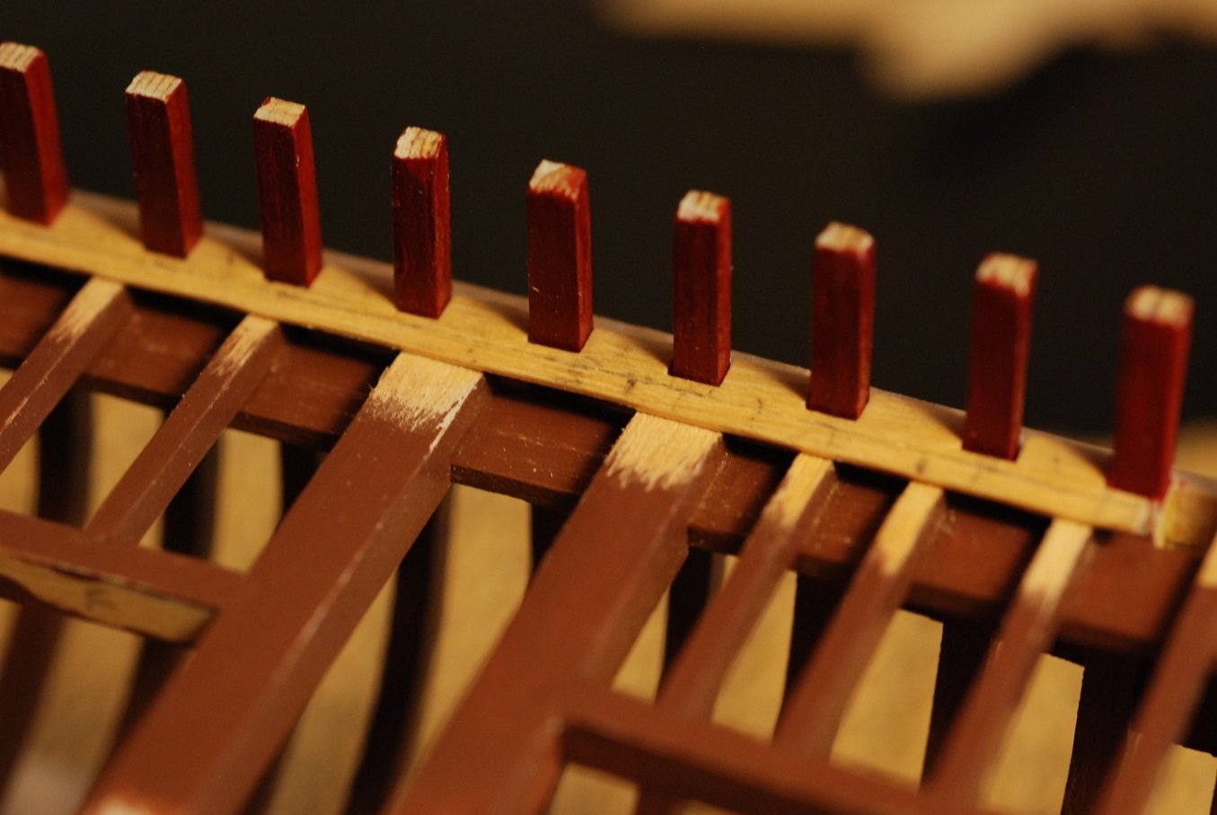
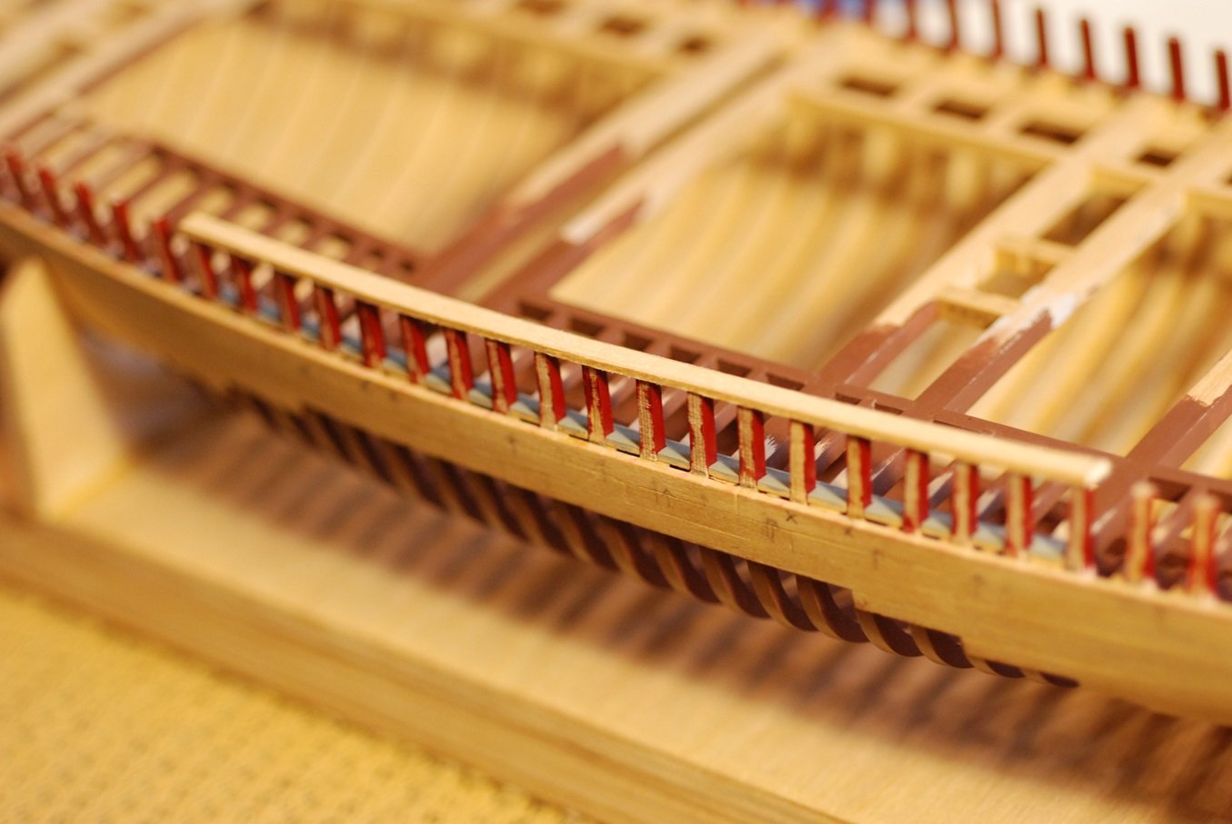
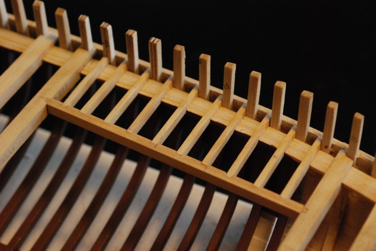
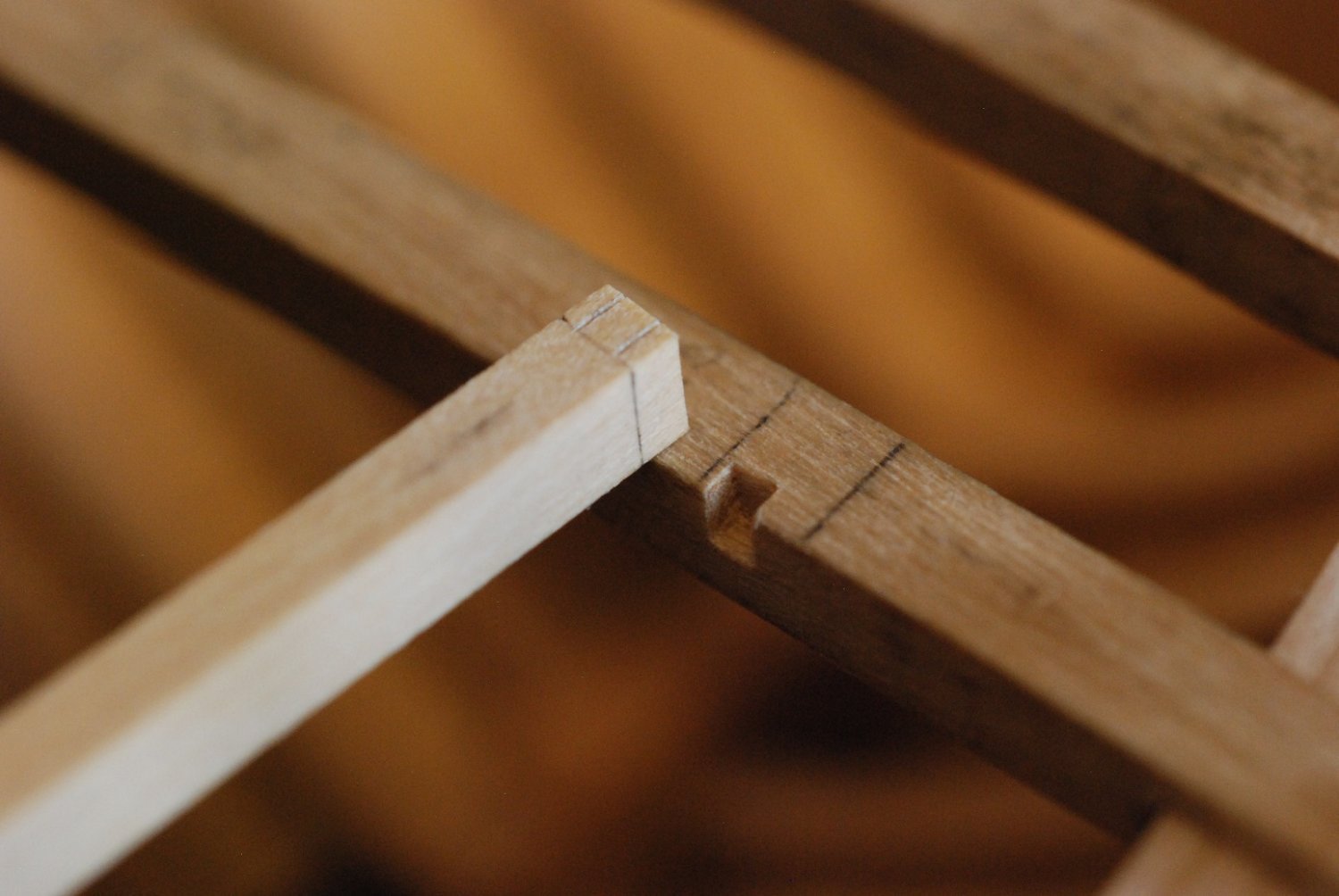
In addition to trimming away wood from the inboard edge, I also carved down the thickness of the remaining excess wood in a way that left an edge that corresponded to the final inboard edge of the covering board. This involved scoring the surface of the piece with the X-Acto, then coming along with a fine chisel and planing away the surface of the piece along the inboard edge. The edge is visible as the bright line in this photo. This will make it much easier to identify the final edge when the last bits of excess are trimmed away, and to create a smooth and fair surface against which the margin plank will rest.
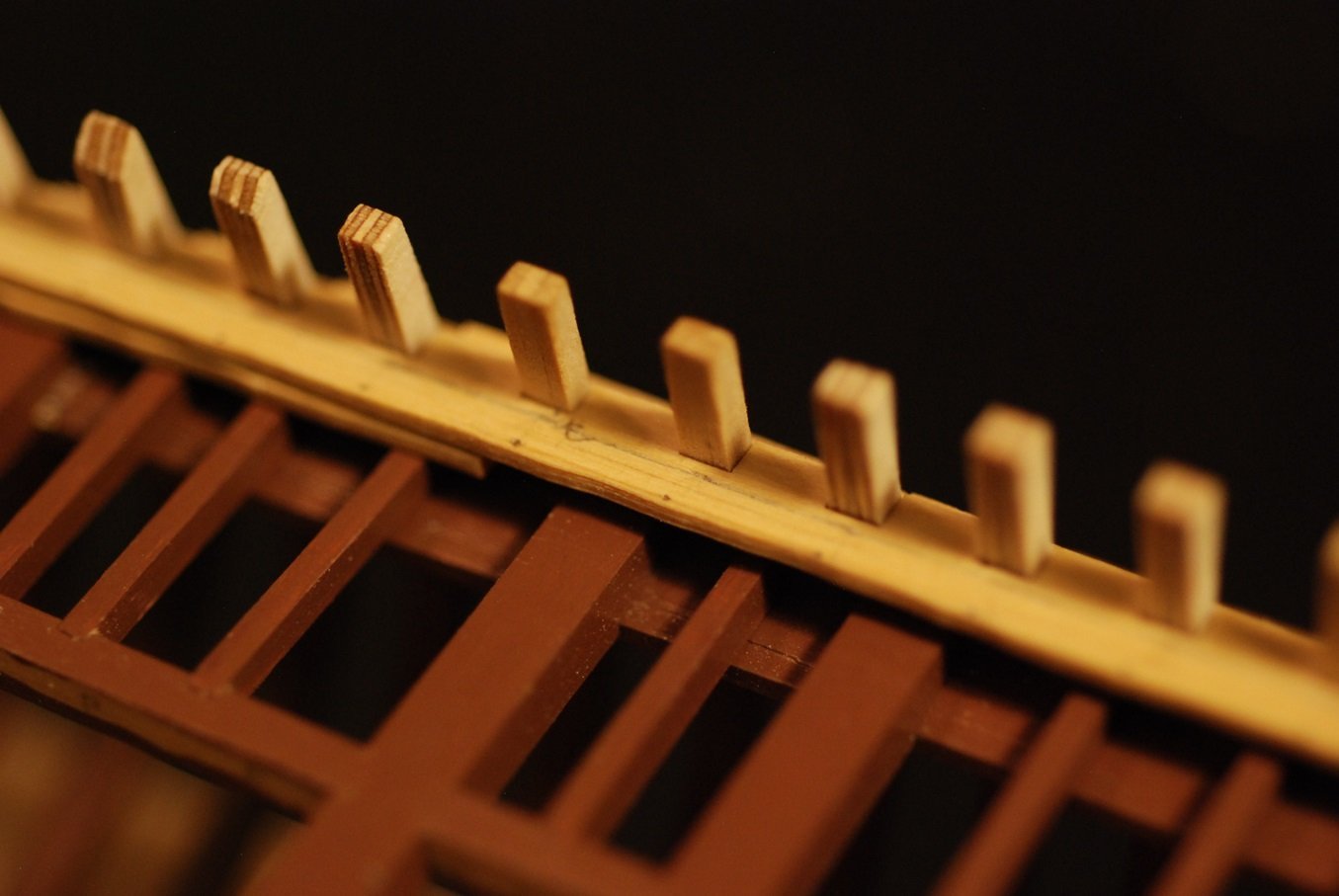
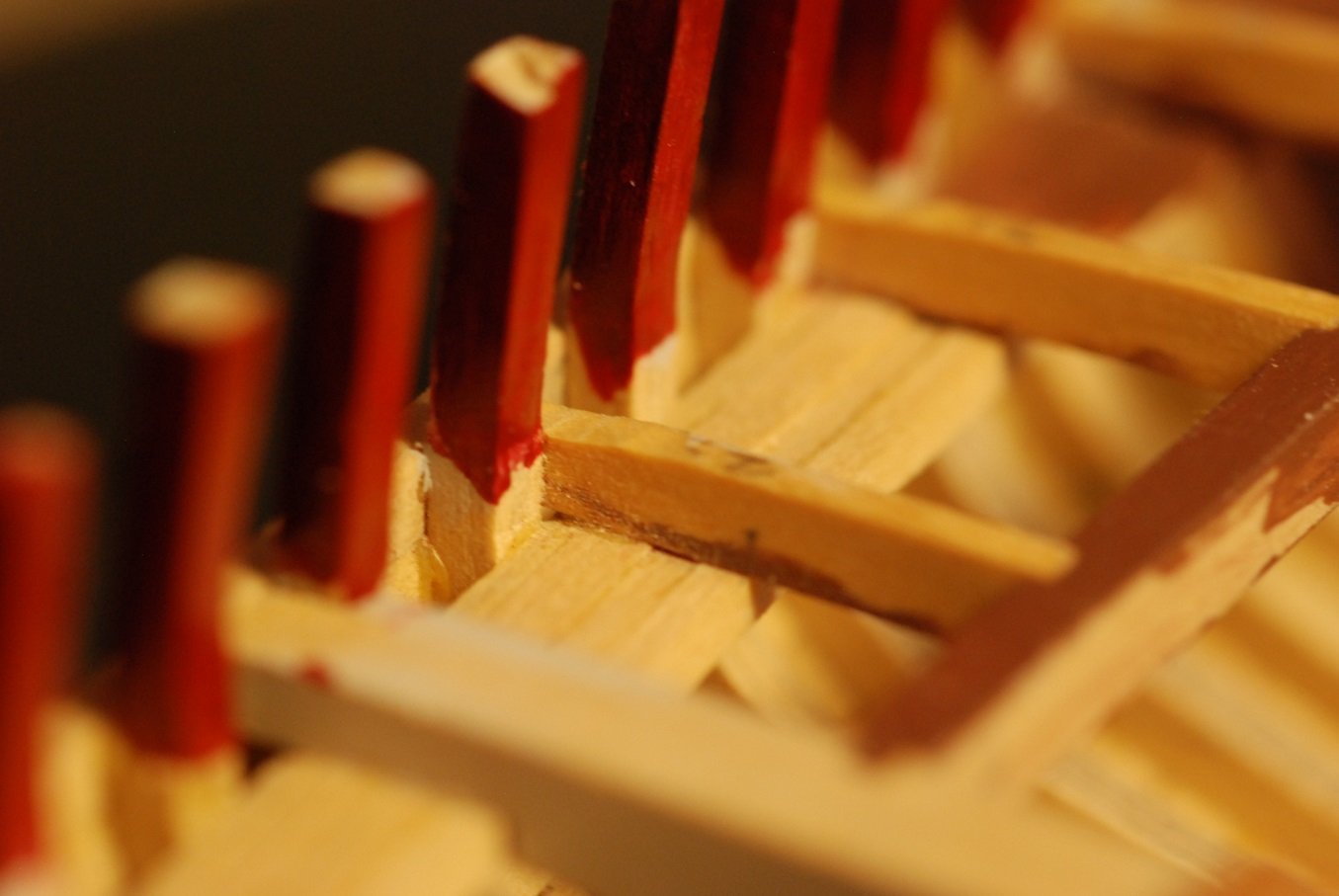
Next problem: now that I have this piece that sits fair when I press it down against the deck beams and ledges, how do I do the glue-up in a way that makes sure that I am not left with the kinds of gaps I can see in this picture? I don’t have that many fingers.
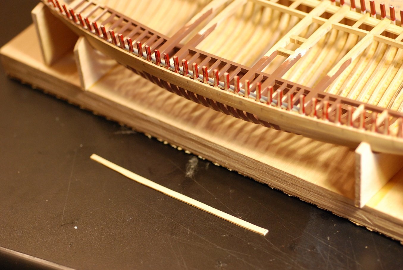
I used a 1/16” thick piece of scrap wood to create a curved piece that roughly followed the curve of the rail, then glued it to the tops of the stanchions.
This is a sacrificial piece that will hopefully come off easily when I am done with the next step.
Some of the stanchions were a tiny bit shorter than their neighbors. These differences will be hidden by the rail and its supports that will be added later.
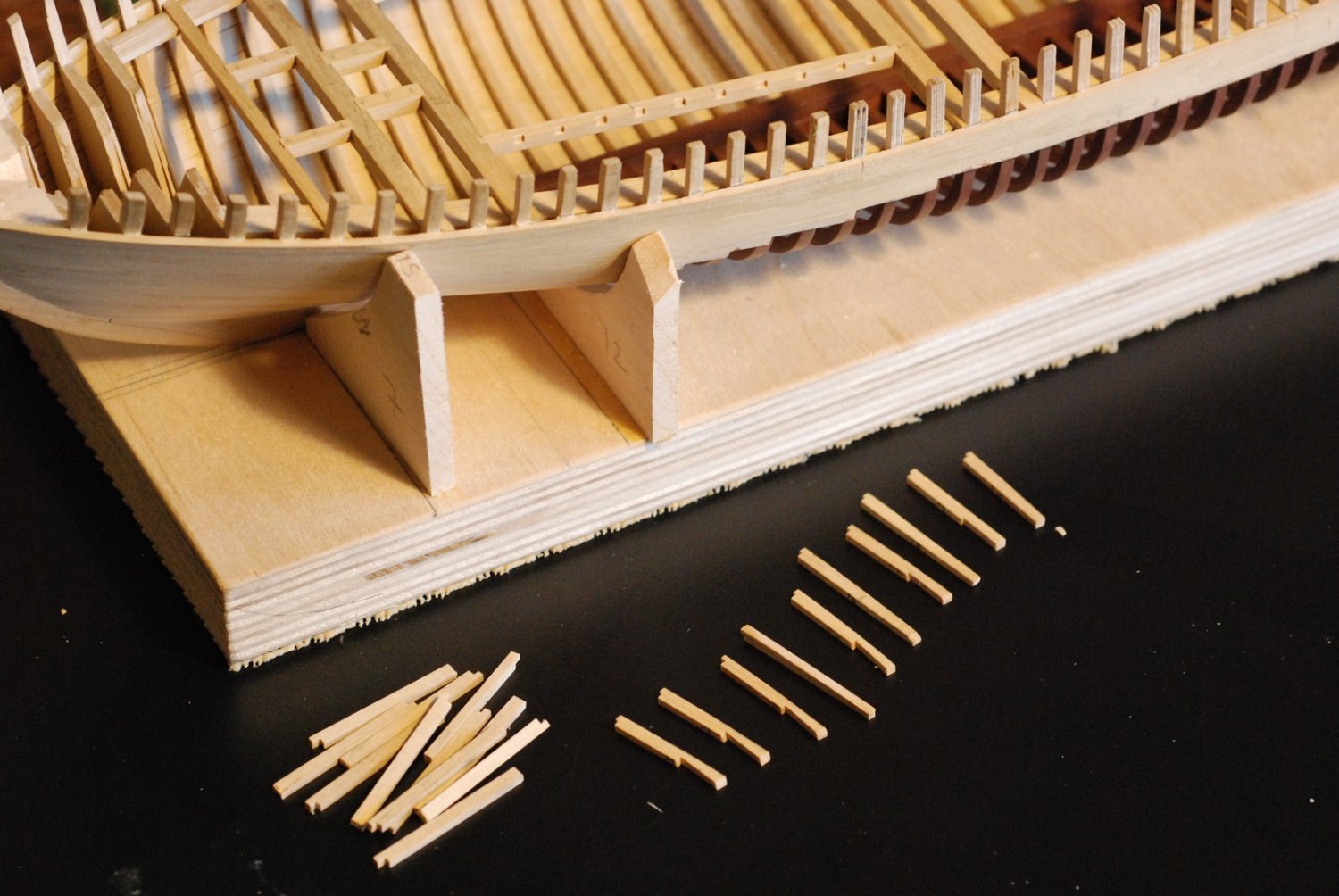
Using scrap wood, wedges of wood thin enough to fit between the stanchions were created.
In preparation for glue-up, the areas of the undersurface of the covering board that will need to be wetted with glue were marked with pencil.
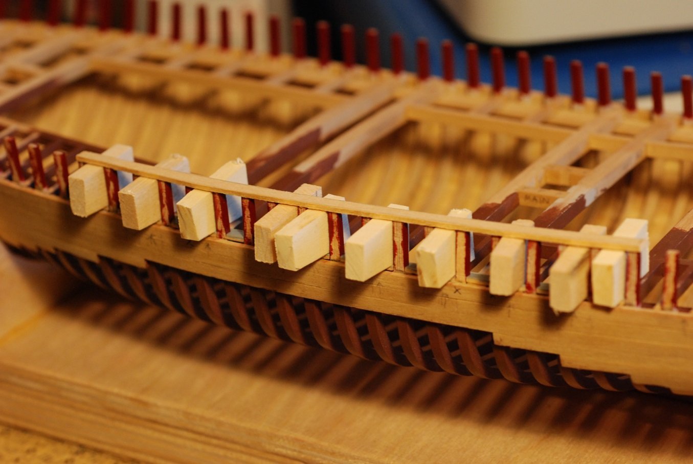
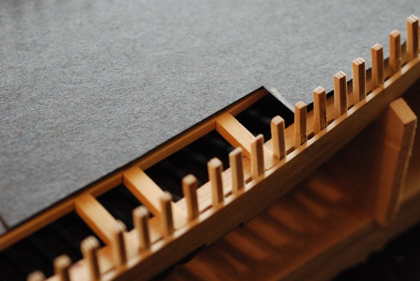
Then the mating surfaces of the deck structure were wetted as well. I put small amounts of glue into the notches of the covering board as well. The board was put in place, and the wedges were used to press them to the surface of the deck structure. Care was taken to make sure that the covering board was pressed in fully against the deck, as well as against the bases of the stanchions, without leaving any gaps.
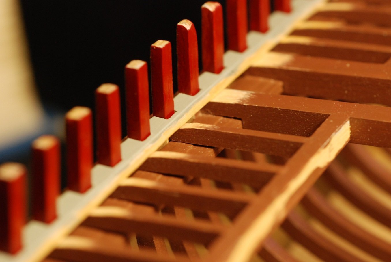
After suitable drying time, the wedges were removed and the sacrificial piece was easily separated from the tops of the stanchions with the X-Acto.
I never would have been able to hand-paint such a clean appearance if I had simply glued up unpainted pieces of wood.
Now I only have to do this five more times, with the remaining covering board pieces! The joints between the pieces in real life would have had an angled appearance resembling a scarf joint, but I won’t be able to duplicate that here.
Once all the covering boards are installed, the next 2 jobs that would make sense are the beginning of the deck planking and also the bulwarks planking. I don’t know yet which I will do next, because it will probably take me awhile to get the rest of the covering boards in place.
-
-
Like I was just sayin'!!
- Keith Black, mtaylor and davec
-
3
-
Great, thanks. I have also found that at these small scales you have to manufacture your own carving tools.
- davec, Keith Black, mtaylor and 2 others
-
5
-
Nice miniature carving work! What kind of tools do you use? Do you use a microscope or visors for magnification?
- Keith Black and mtaylor
-
2
-
Oh no, Mark! I am sorry to hear of the medical setback, after having met you this past October! But I went through the same thing myself in 2019 involving my left S1 nerve root so I feel your pain. If you have access to a work surface that is height adjustable, it may make a big difference.
-
Thanks for the likes, everyone. Jerome, yes Barry and Jen still own and run the Mary Day. I am in regular contact with them and I hope to see them next month.
- FriedClams, jerome and Keith Black
-
3
-
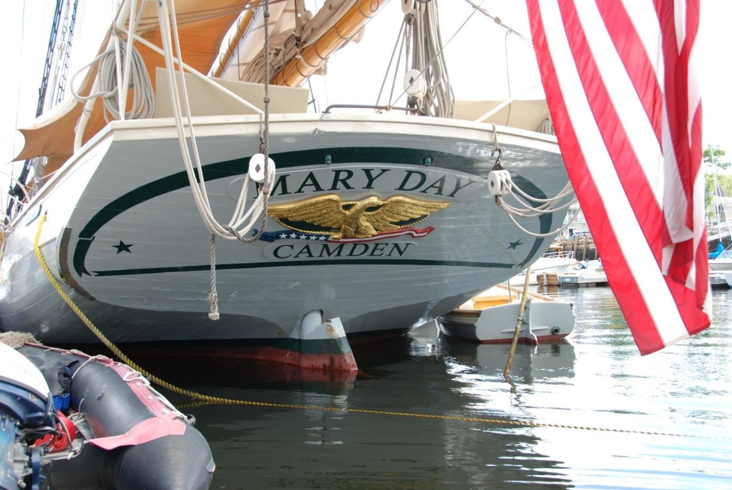
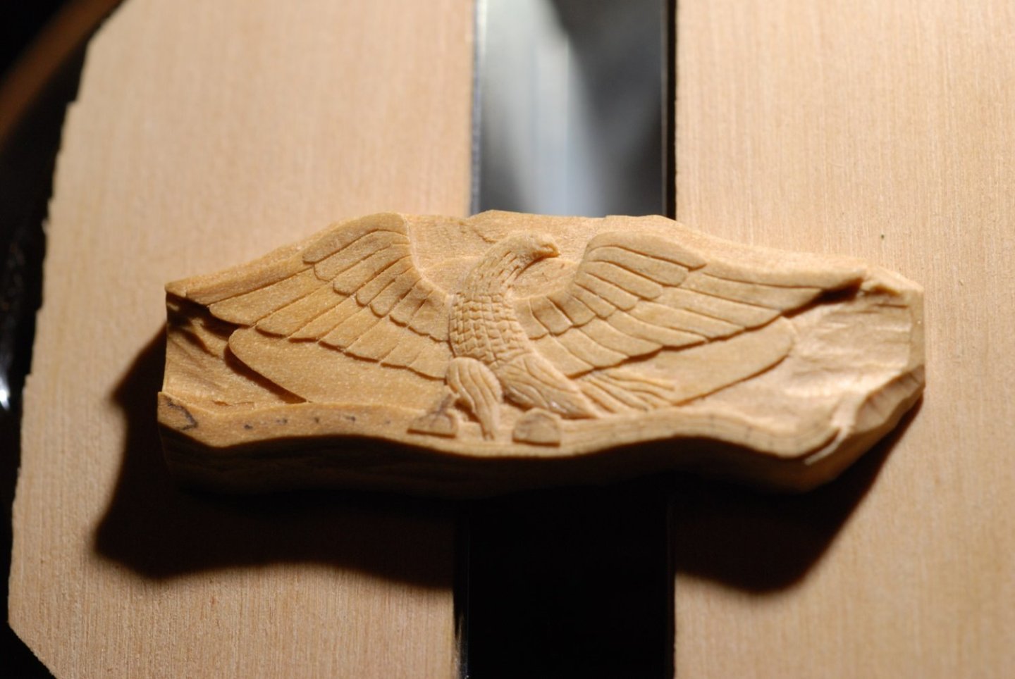
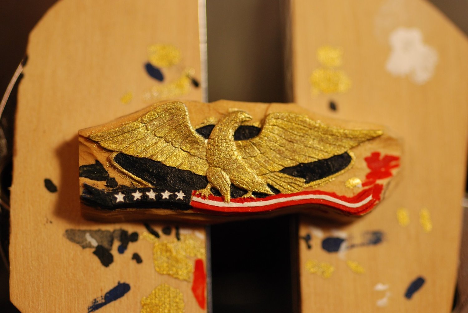
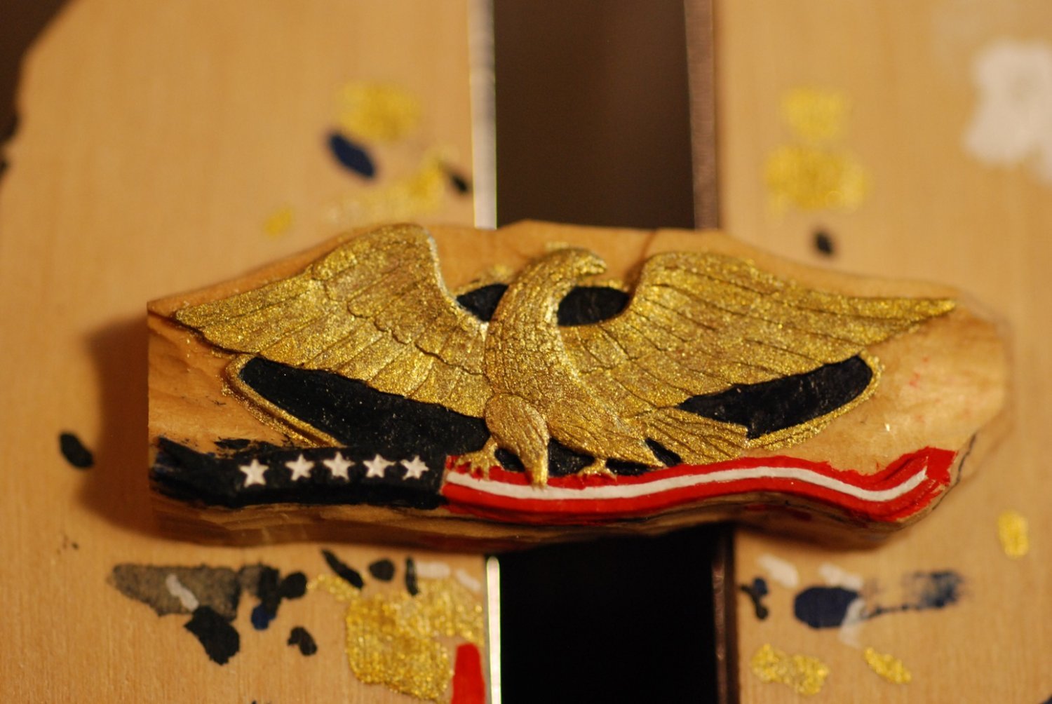
Back in July I lost momentum on working on the hull of the model. Happily, one of the distracting projects was deciding to work on a carved version of the transom carving, shown above. This decoration was added to the schooner after its refit in the year 2000 time frame. I don’t know who created the carving for them.
In the off season, the carving hangs on the wall at the skipper’s house. I took a picture of the carving hanging on the wall in the winter of 2022. Its actual dimensions are 5 ft 9 inches across and about 2 feet in height. Its approximate thickness is 3 inches total. At 3/16” scale, this will translate to a total width of just over 1 inch.
I was able to take an image and reduce it to the appropriate scale, then I used tracing paper to copy the outline of the shield, pennant, and eagle. This was then transferred to a piece of boxwood about 1/8” thick. To be safe, I transferred the pattern to two pieces of wood in case I screwed something up along the way. So far, though, the backup piece has not been necessary.
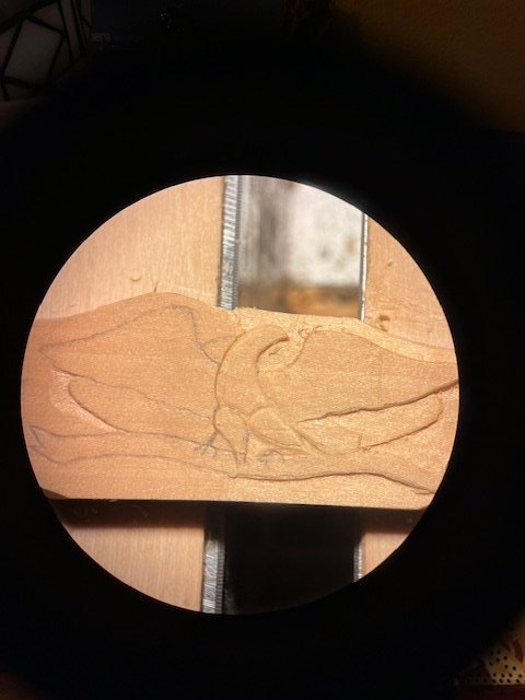
This and other pics that look like it were taken through the viewpiece of my microscope. The traced pattern is evident, and I have already started working out the right side of the eagle, shield, and pennant.
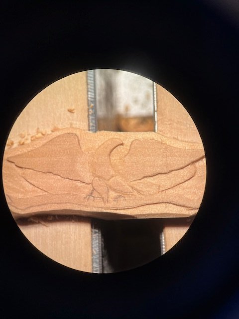
Now both sides are getting worked out.
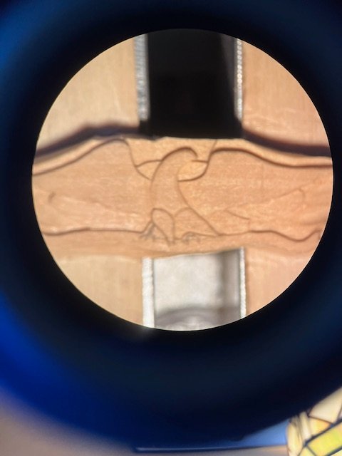
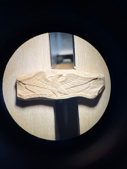
This photo shows some relief involving the body and legs of the eagle.
Now jump forward substantially, and lots of details have been worked in. Dots on the pennant indicate where the stars will be. The talons haven’t been worked out yet.
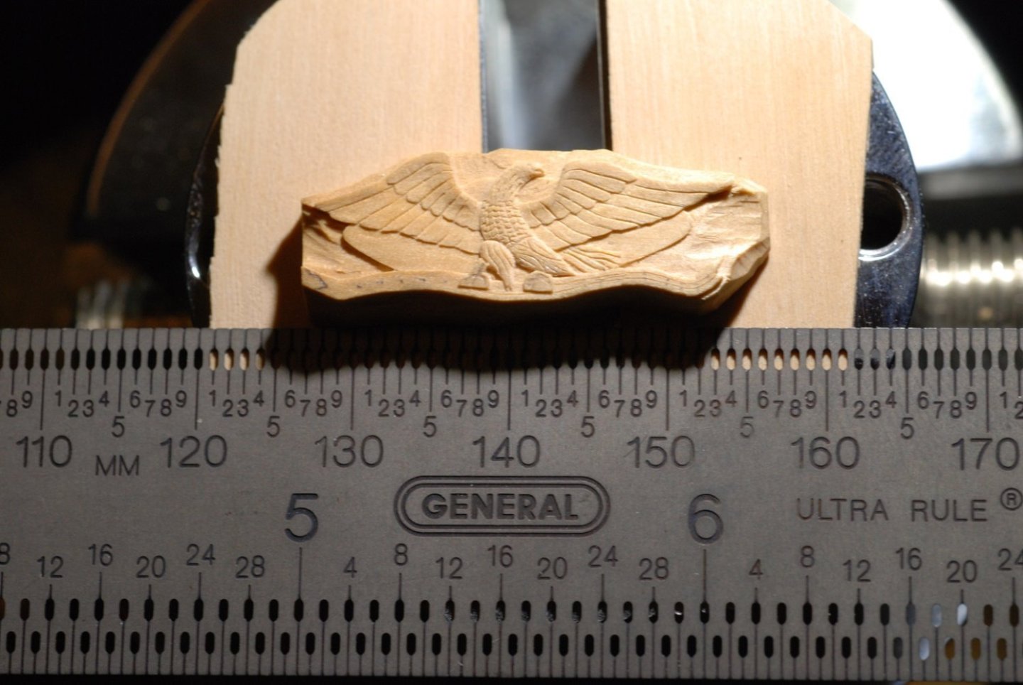
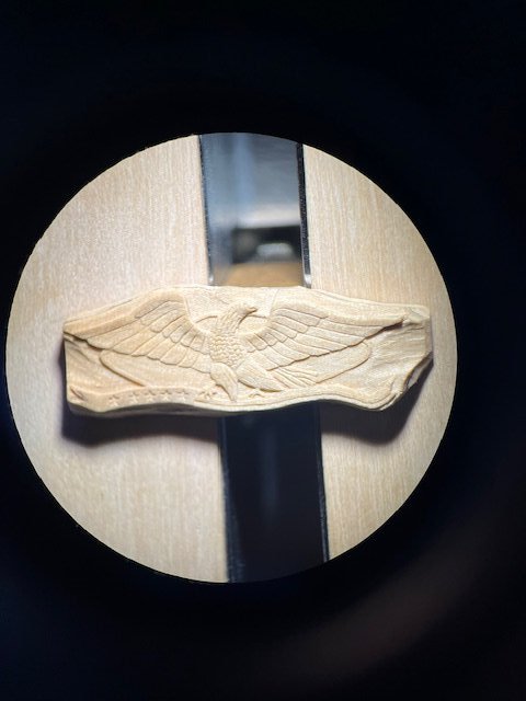
As predicted, the carving has a maximal dimension of just over 1 inch.
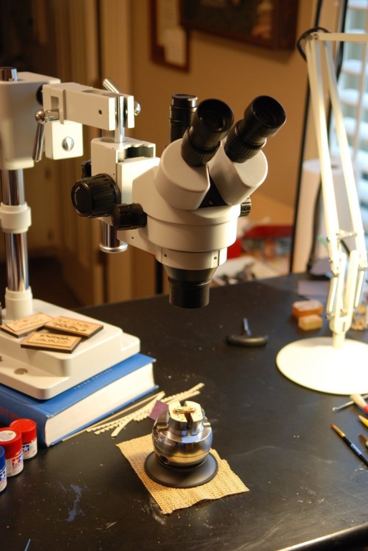
This is my microscope setup. Thanks to Margie Buckingham, widow of Doug Tolbert, who offered for sale this articulating microscope!
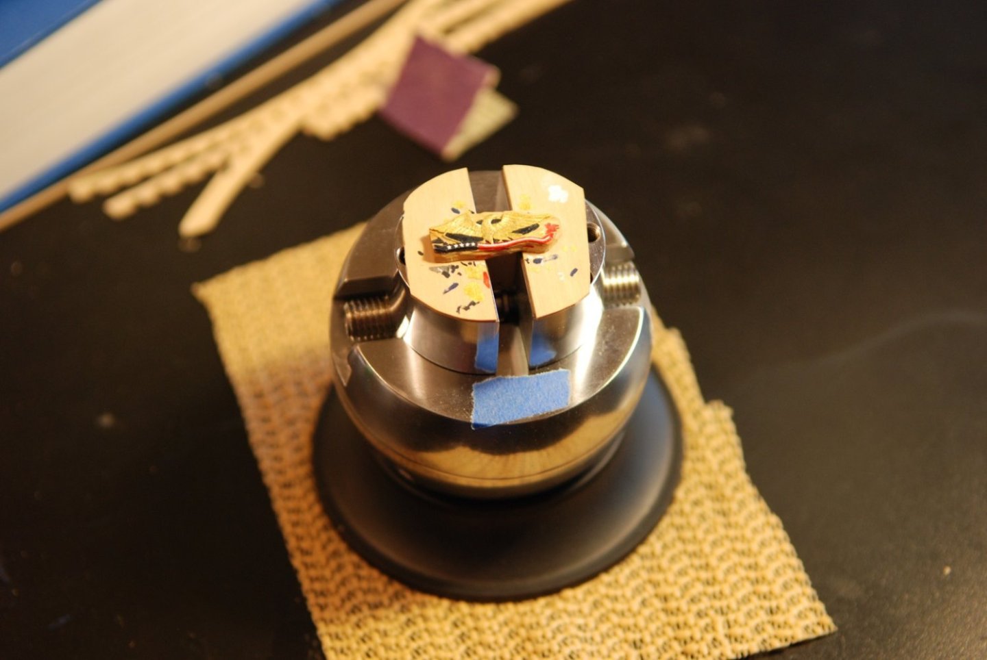
A jeweler’s ball vise is essential for this kind of work.
And now I am carving out the stars from the surface of the blue area of the pennant. The talons have also been defined.
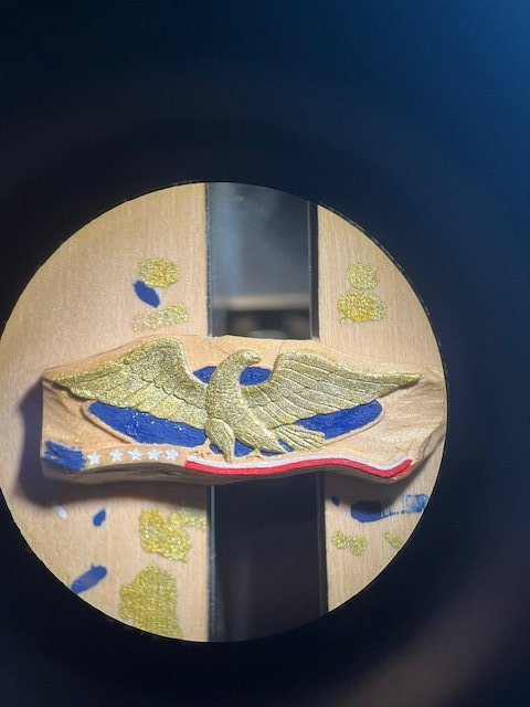
Painting is now under way. The blue is much too electric, so I added a small amount of black paint to it. White paint has been dropped into the recessed stars. I was warned that the paint may obscure the surface details of the eagle, but I was pleased with how it turned out.

I have darkened the blue paint. Much better.

And now I have carved away some of the splotches of paint that were on the backing wood.
So after about 45 hours of work, it is pretty much finished! When the time comes to mount it, I plan to very carefully carve off the wood from the backside of the piece. The piece and its backing is glued to a separate piece of wood that is clamped in the vise. Rather than soaking the piece to free it from the other piece of wood, I plan to gradually carve it free. I will wait to do this step until it’s time to mount it because the freed piece will be exceedingly fragile on its own and I don’t want to risk damaging it. The workpiece started out as a 1/8” thickness piece of wood, and when I am done carving off the backside it will be around 1/16” in thickness. Wow.
I am happy to report that I have regained momentum on the rest of the model project, so I should soon have a new post that is about the covering boards.
-
Hi John, thanks for your post. I bet the Wawona is well documented and should make for a very interesting build!
I will be posting some stuff here soon as I regain momentum on my build project.
- Keith Black and allanyed
-
2
-
-
It's funny that at first I couldn't tell what was going on in that picture of the milling machine and bit, until I zoomed in and saw the rounded head bit and the wooden column beneath it. That's great stuff!
- allanyed, Keith Black and mtaylor
-
3
-
The covering boards are very complicated and completely bespoke pieces. Still working on them and I hope to have an update soon. I am just hoping that I don’t break any of them!
- Keith Black, Retired guy, Rick310 and 1 other
-
4
-
-
So Johann, what did you make the sleeve out of? A thin layer of leather?
- Keith Black and mtaylor
-
2
-
-

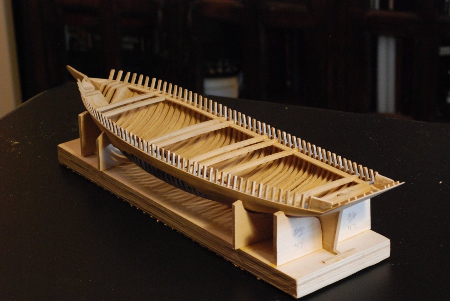
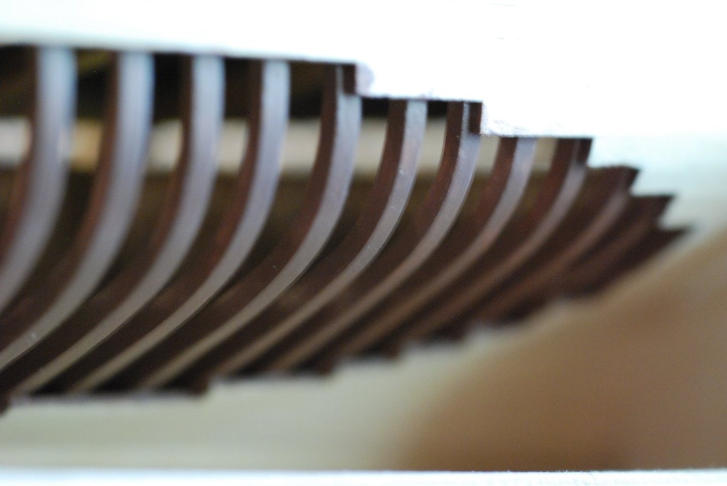
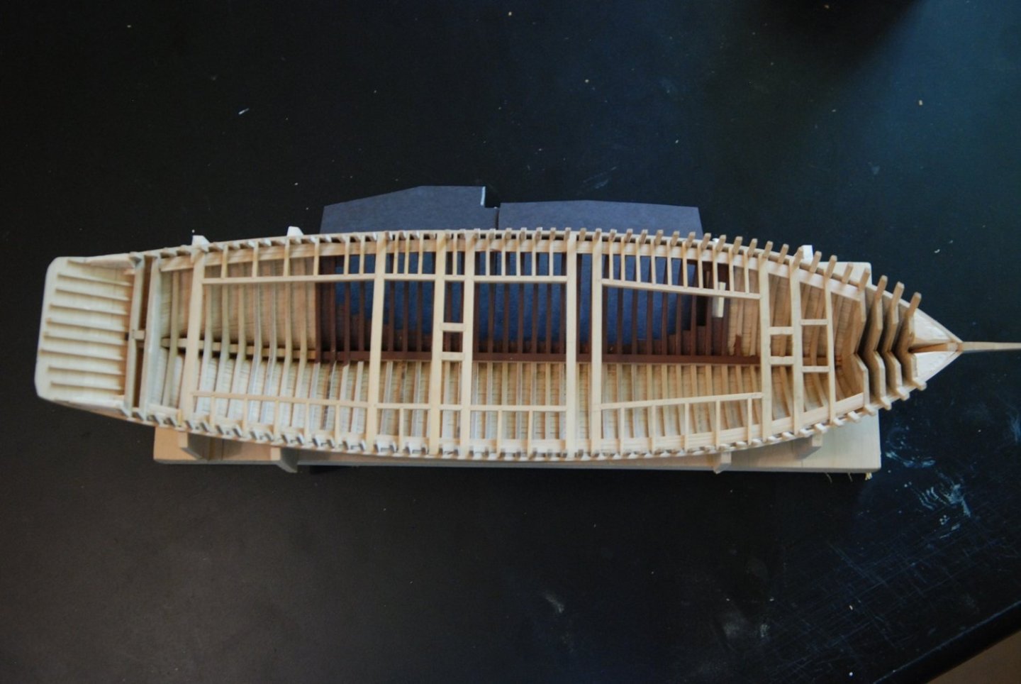
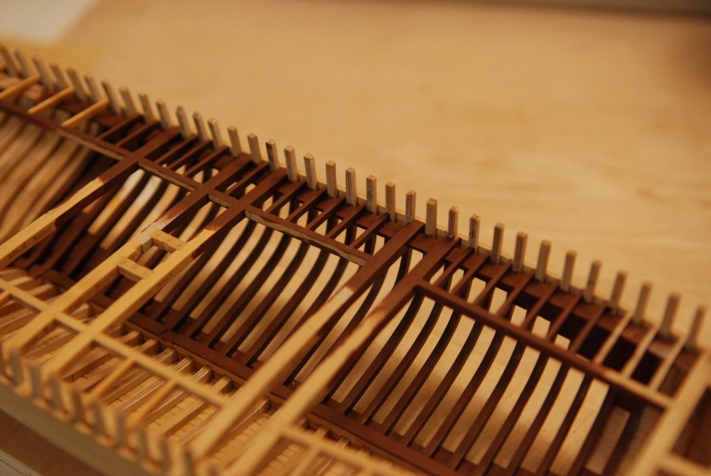
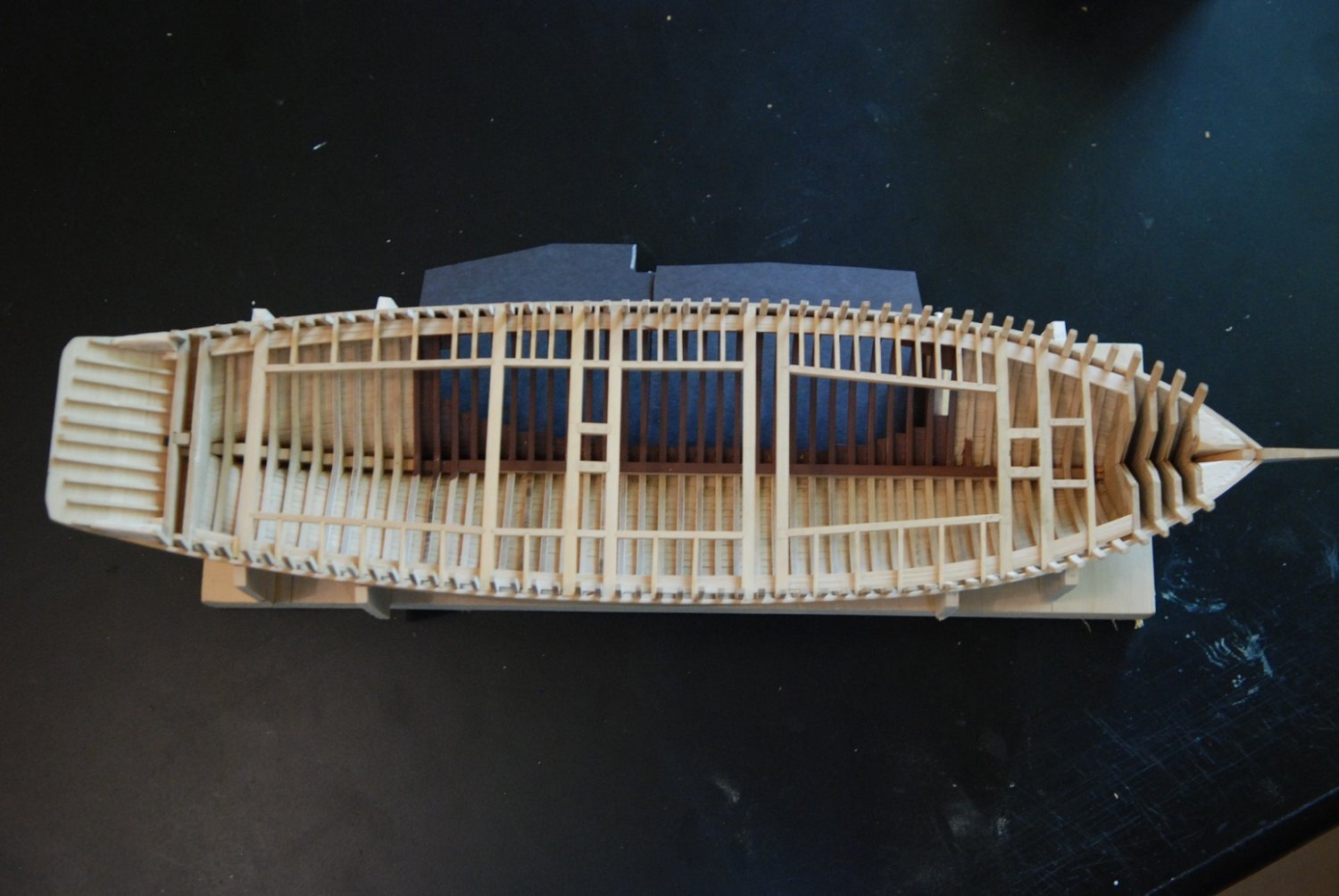
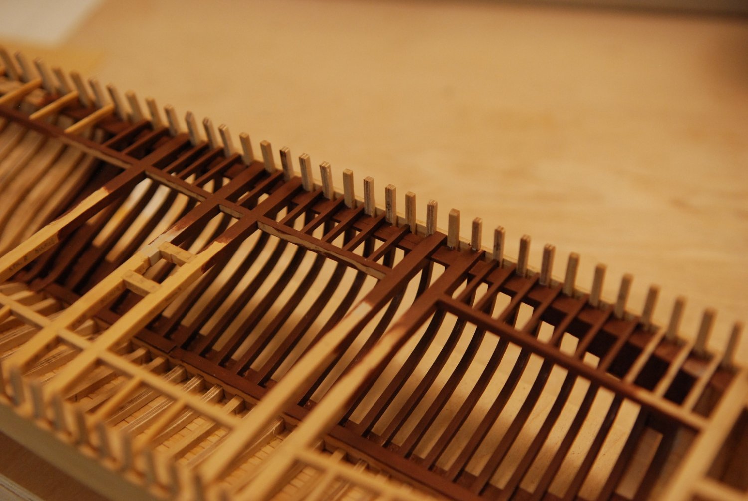
Time to start building the deck structure, which will help solidify the sides of the hull. I had been thinking about installing temporary spalls, but the shape of the hull seemed very stable without them and it didn’t seem to change much when I was fitting the deck beams at the point of maximum beam.
I made a pattern template for the curvature of the beams to match the camber of the deck on the actual ship. On one of my visits to the Mary Day, I strung a string from one side to the other at the point of maximum beam, secured with tape to a stanchion on each side. I then dropped the string on each side until it barely touched the deck in the centerline, then measured the height at each stanchion. The rise in the centerline was 4.5”. I then used the method described by Chapelle in his Boatbuilding text to draw out the appropriate curve on cardstock. Which is challenging to do at this small scale. This was then transferred to a piece of wood for additional stability.
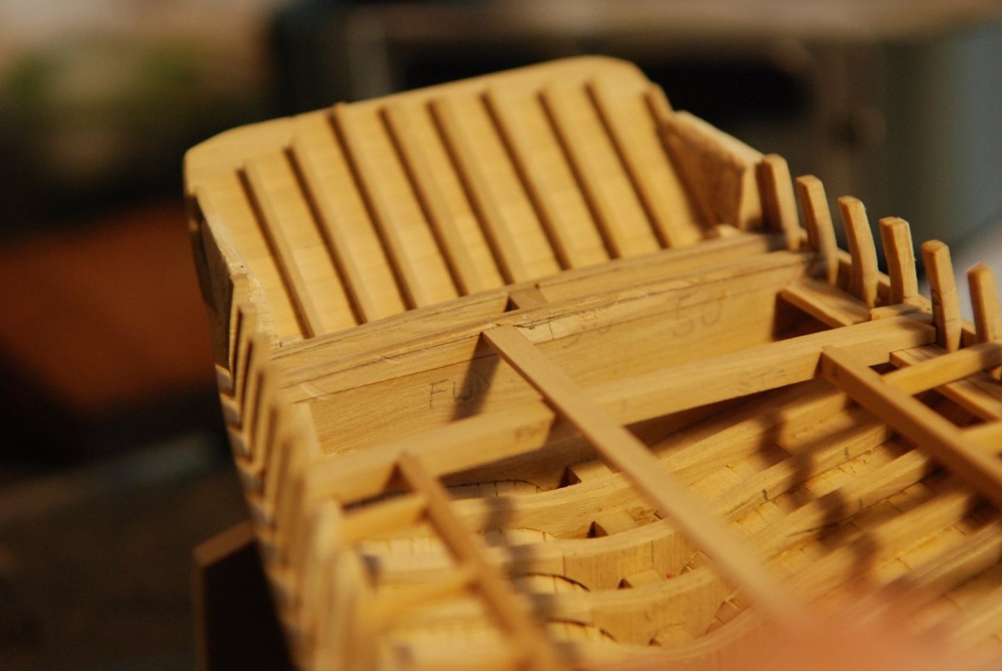
Some of the beams were made with Castello boxwood, while I started to splurge with some English (Buxus) boxwood for some of them so I could see if it was noticeably different from the Castello. The pattern was transcribed onto stock of appropriate thickness, for both the upper and lower surfaces of the beams. Multiple pieces of appropriate length were created, and the center point on the curve was also transferred to each piece.
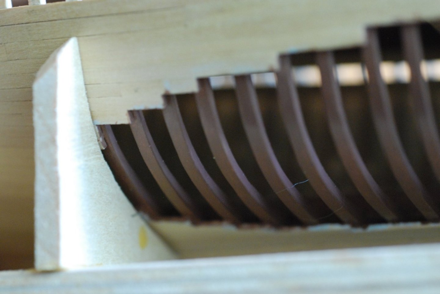
The joint of each beam with the planking and each beam shelf was often very complicated and called for a lot of trial fitting. Trimming at each end was very gradual and symmetric in order to try to preserve the position of the centerline marks.

There were multiple facets of the joints that had to be trimmed in a symmetric fashion, as the beams articulate with not just the beam shelf but also with the frames themselves.

This beam is almost completely flush with the sheer strake.
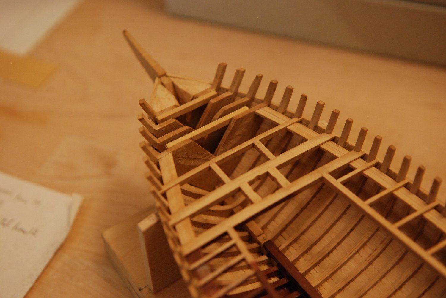
A lot of work just to install the eight deck beams, and that was after I decided to neglect some beams normally found near the stern.
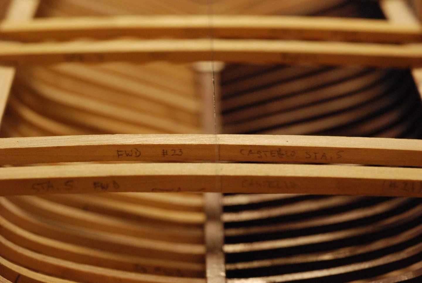
These Castello beams have their center points marked. There is a fine thread strung from stern to stem, and it appears that they don’t quite line up. The difference is about 1/32”. I am thinking that the stem may be leaning to one side a tiny bit.
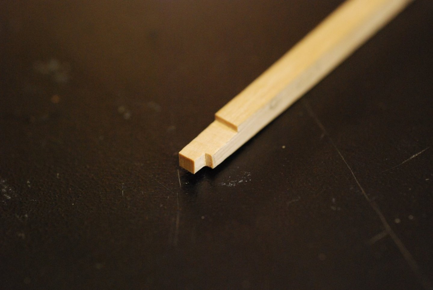
Next up are the carlings that make up the support for the deck houses. This will be my first opportunity to cut joints. The plans indicate dovetail joints, but I decided to cut square joints.
Marking off the joint locations and cutting the carling to length.
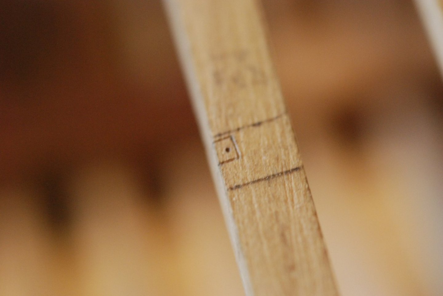

The microscope was a huge help in cutting these joints.

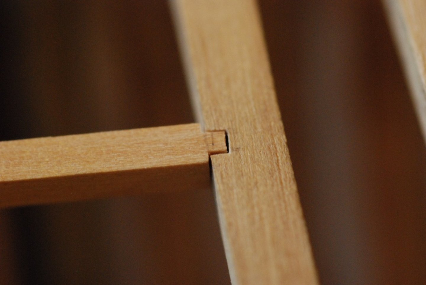
This joint actually has a bit more of a gap in it than I was shooting for. But overall they made for a very rigid deck structure, and it was a very satisfying process.

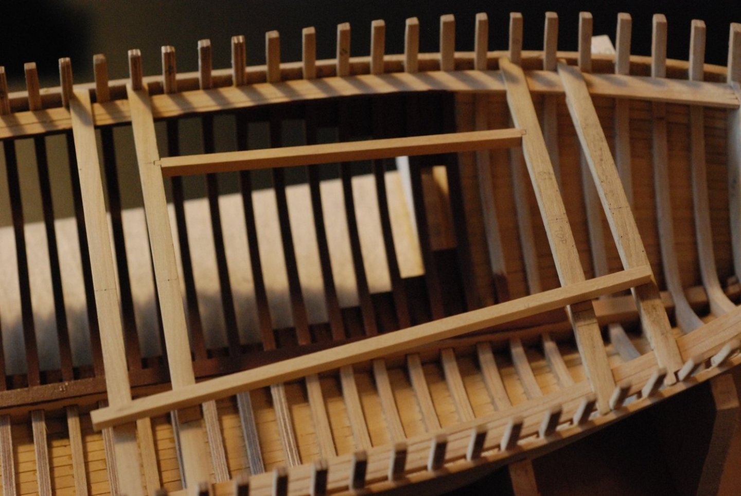
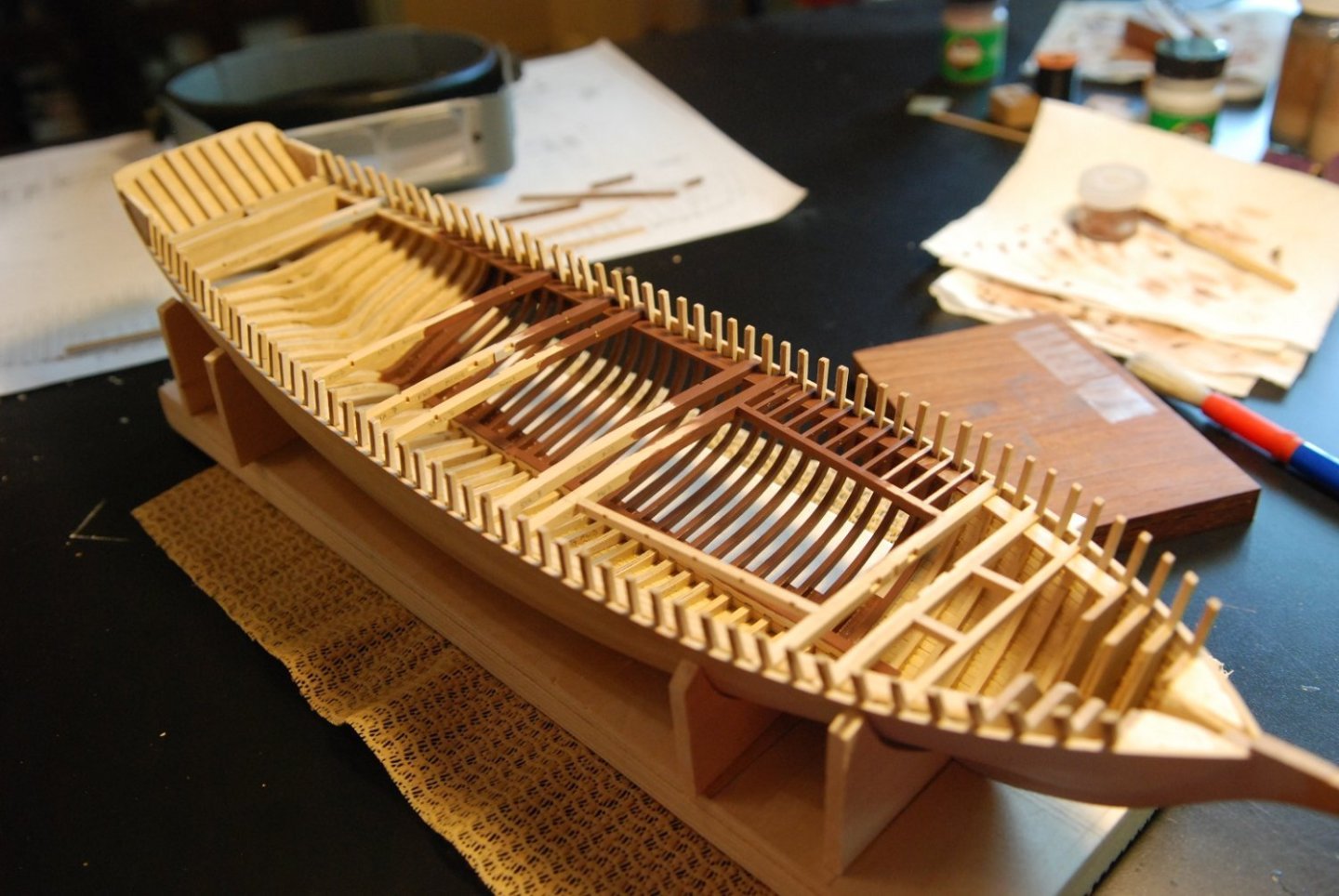
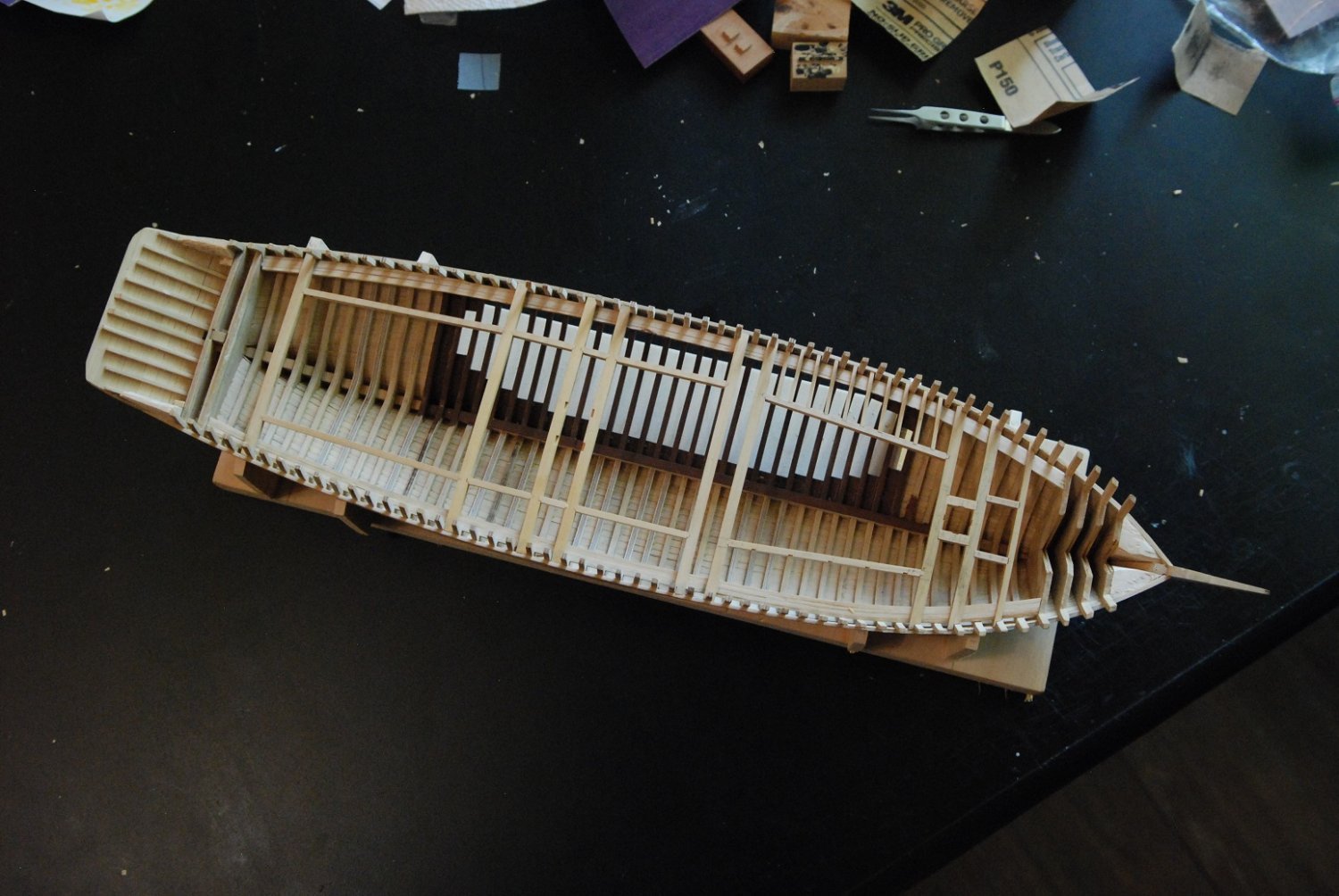
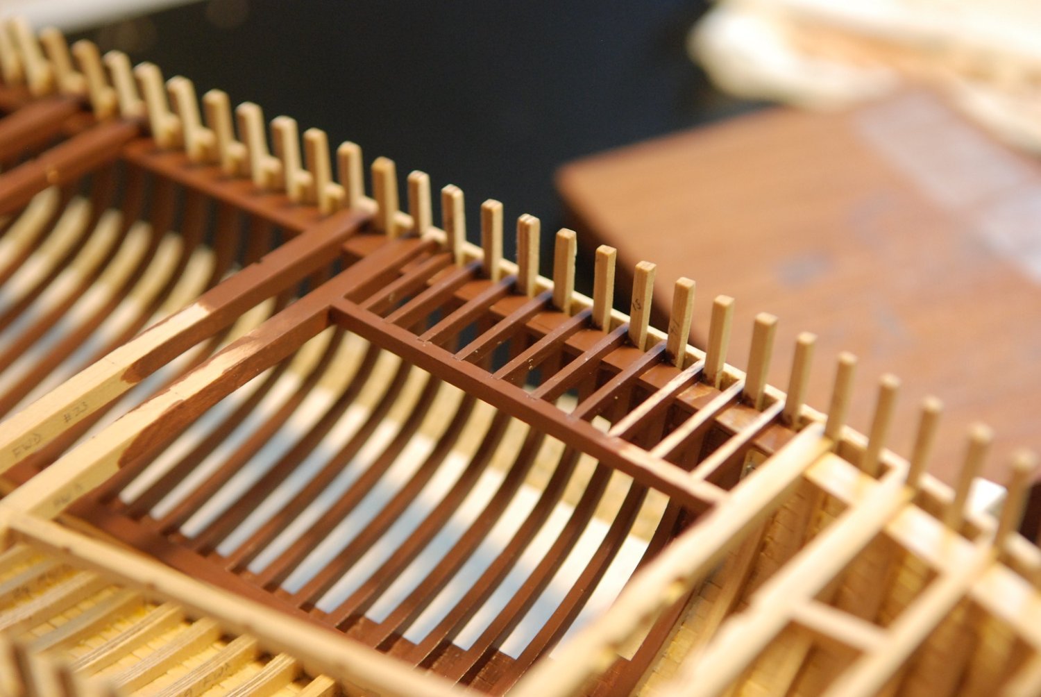
Time for the ledges. In the areas of the deck that are to remain unplanked, all of the ledges will be installed. But in the areas to be covered over, I decided to install every other ledge.
This particular carling was a lot of work, with ten joints in it. Each had to be placed accurately, so that the ledges would stay parallel and would articulate properly with their corresponding frames.

Due to all this trial and error, I set the model right next to where I was cutting the joints under the microscope so I didn’t have to keep getting up from the microscope and go back to the workbench.
Each ledge was of course unique, as they had to be of the proper length, they had to have proper camber, and they had to be notched on the underside to articulate with the beam shelf.

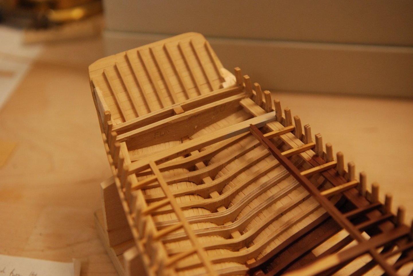
Port and starboard side surrounding the forward deckhouse is done. Also installed are coamings for a forward hatch, as well as the mast partners.

Now moving towards the stern, with all but one carling trimmed to length and installed.
All carlings cut to length. But not glued in place yet, until I was satisfied with how everything articulated.

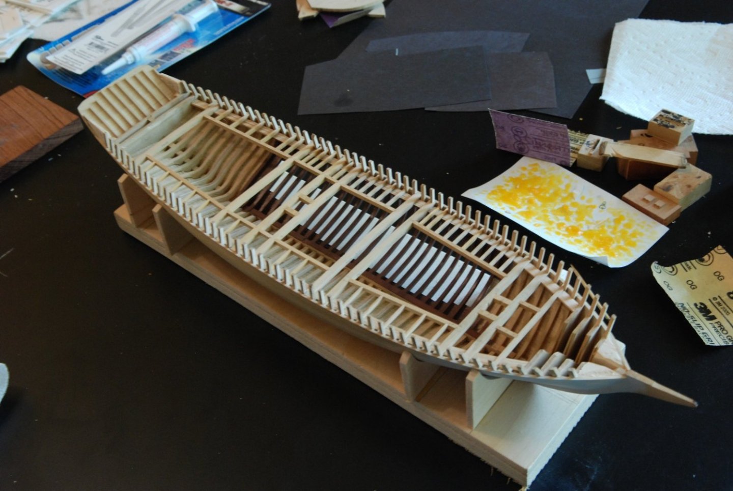
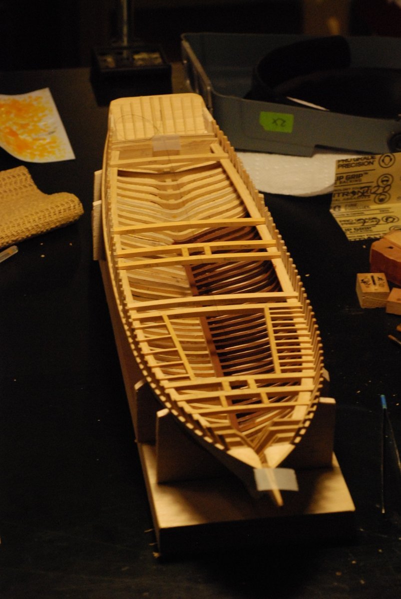
In order to make sure that I painted all interior areas that would be visible following deck planking, I covered the entire deck with the exception of the area that would remain unplanked, then visually inspected the interior. Fortunately it looked like everything was covered.
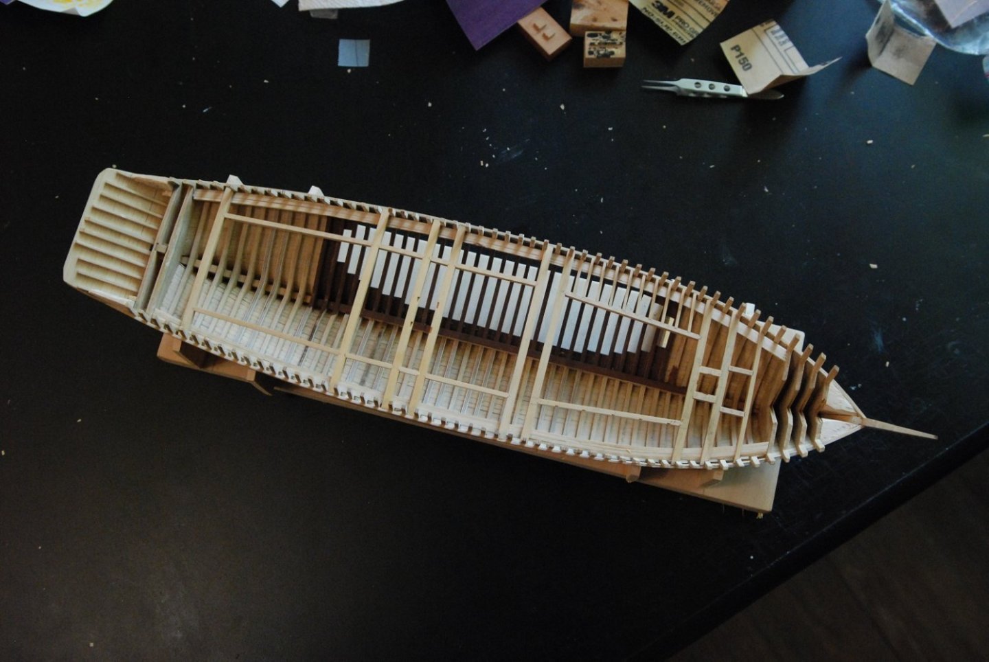
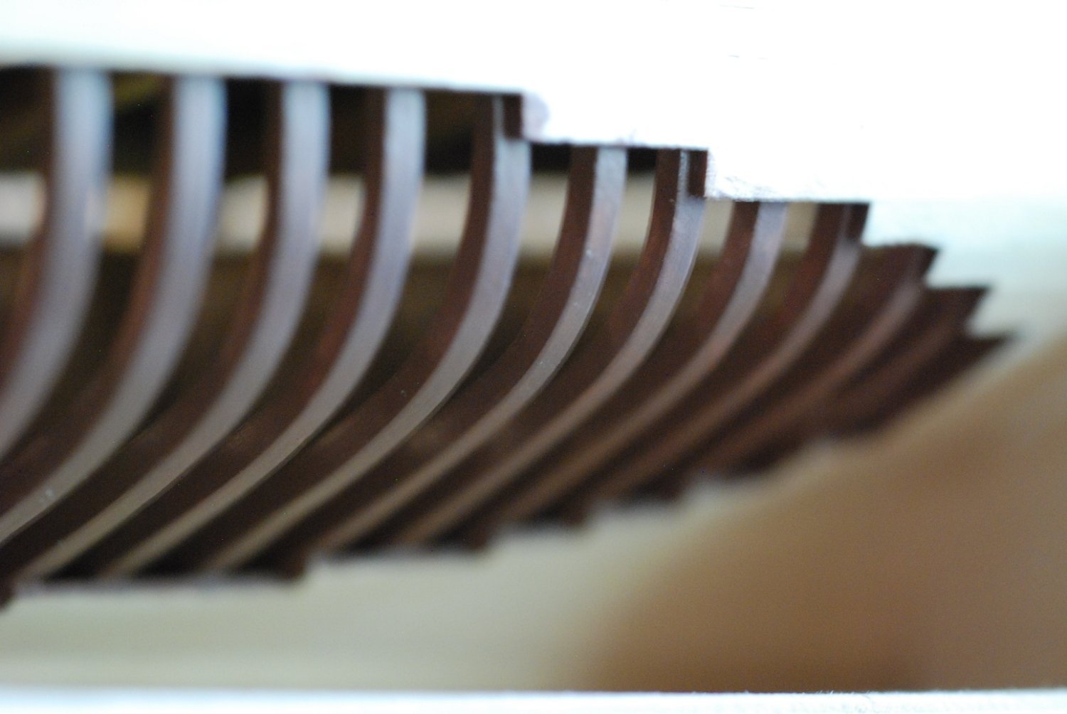
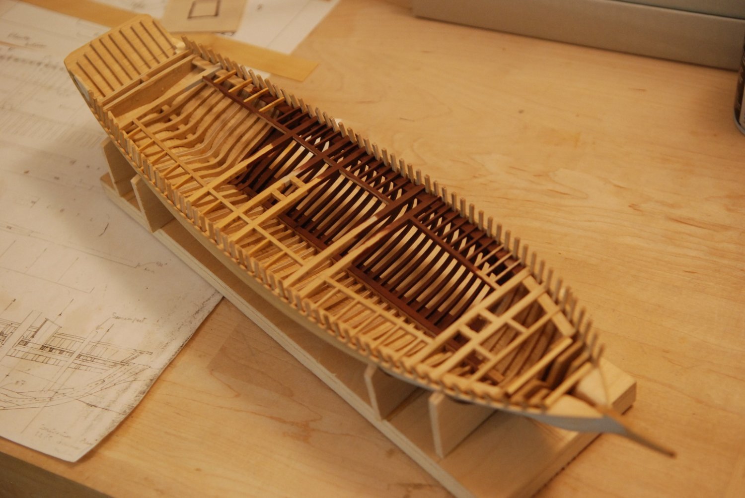
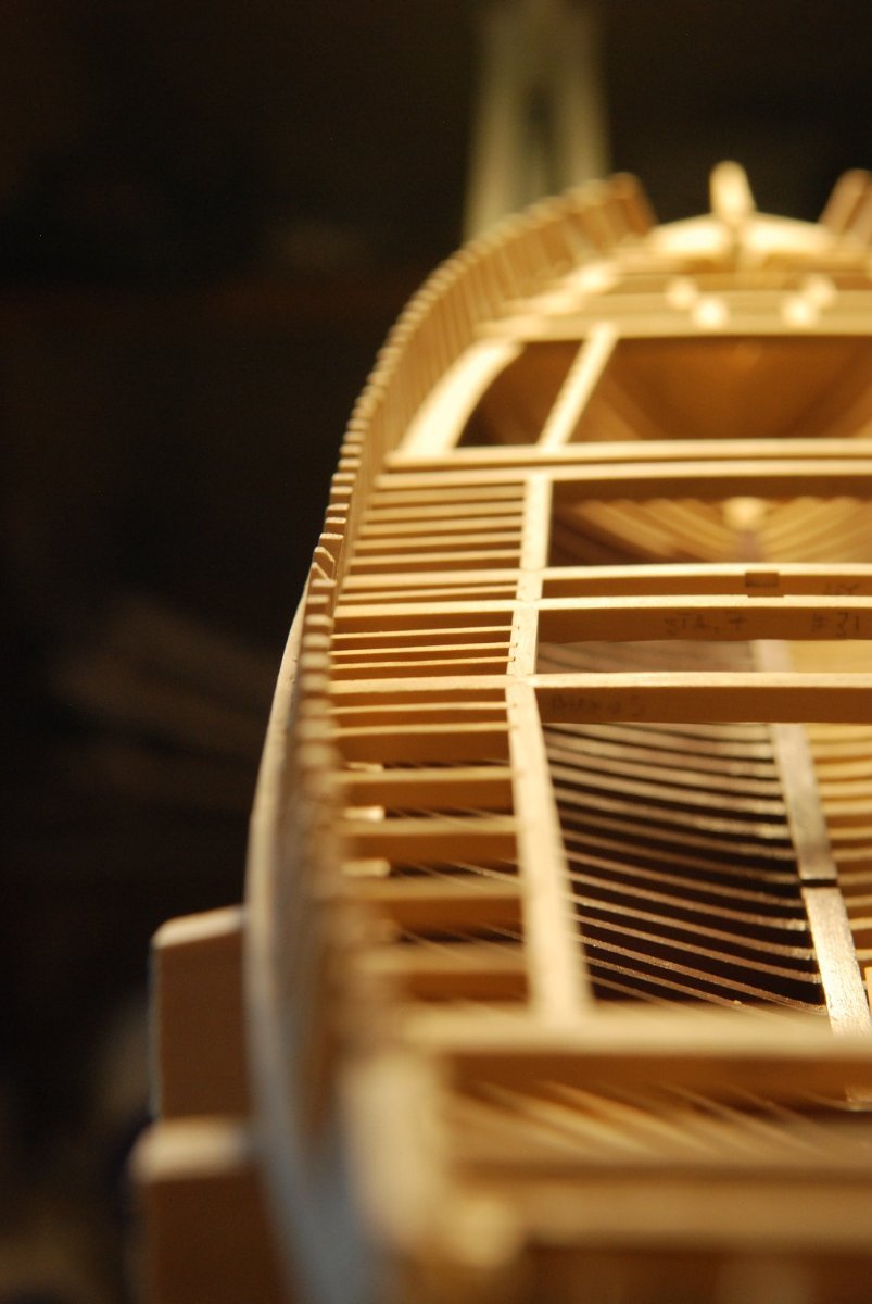
Pretty happy with how the frames have turned out.
Painting this area accurately will be tricky, since I will want the exterior surface painted accurately, but the cut surfaces of the planks will need to be brown.
All beams, carlings, and ledges were dry-fitted to make sure everything is shipshape. Then, the ledges in the area that will be exposed were removed and everything else was glued into place.

Before painting the areas that would remain exposed, I addressed cutting down these two bulkheads at the stern to appropriate height. The more forward of the two was marked using a template of the deck camber.
The excess was carefully chiseled away to allow for a fair run of planking as dictated by this batten.
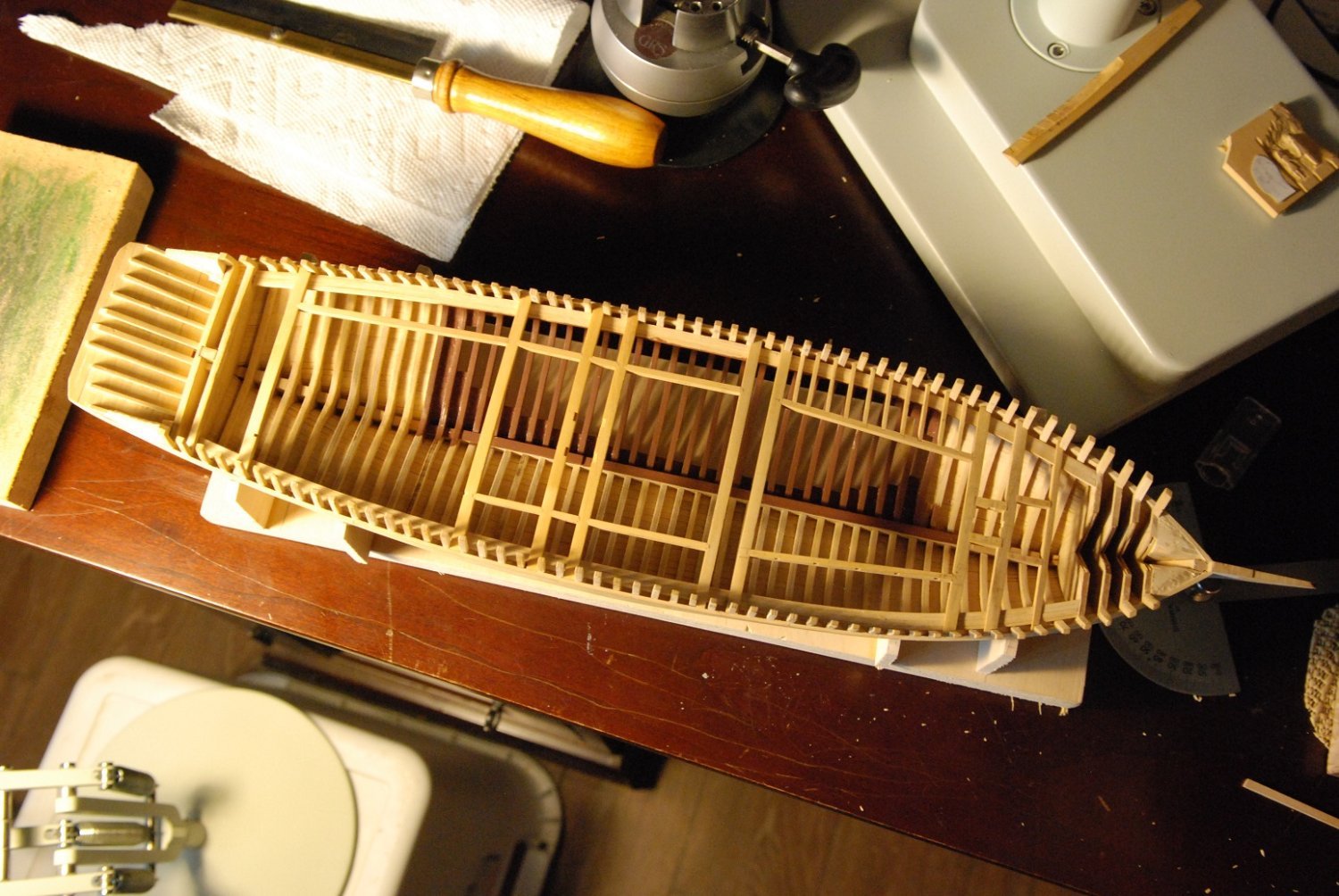
Painting of the exposed deck structure was then performed. The beams and carlings were painted, sanded, and re-painted while in place. The ledges were painted to appropriate smoothness prior to installation.

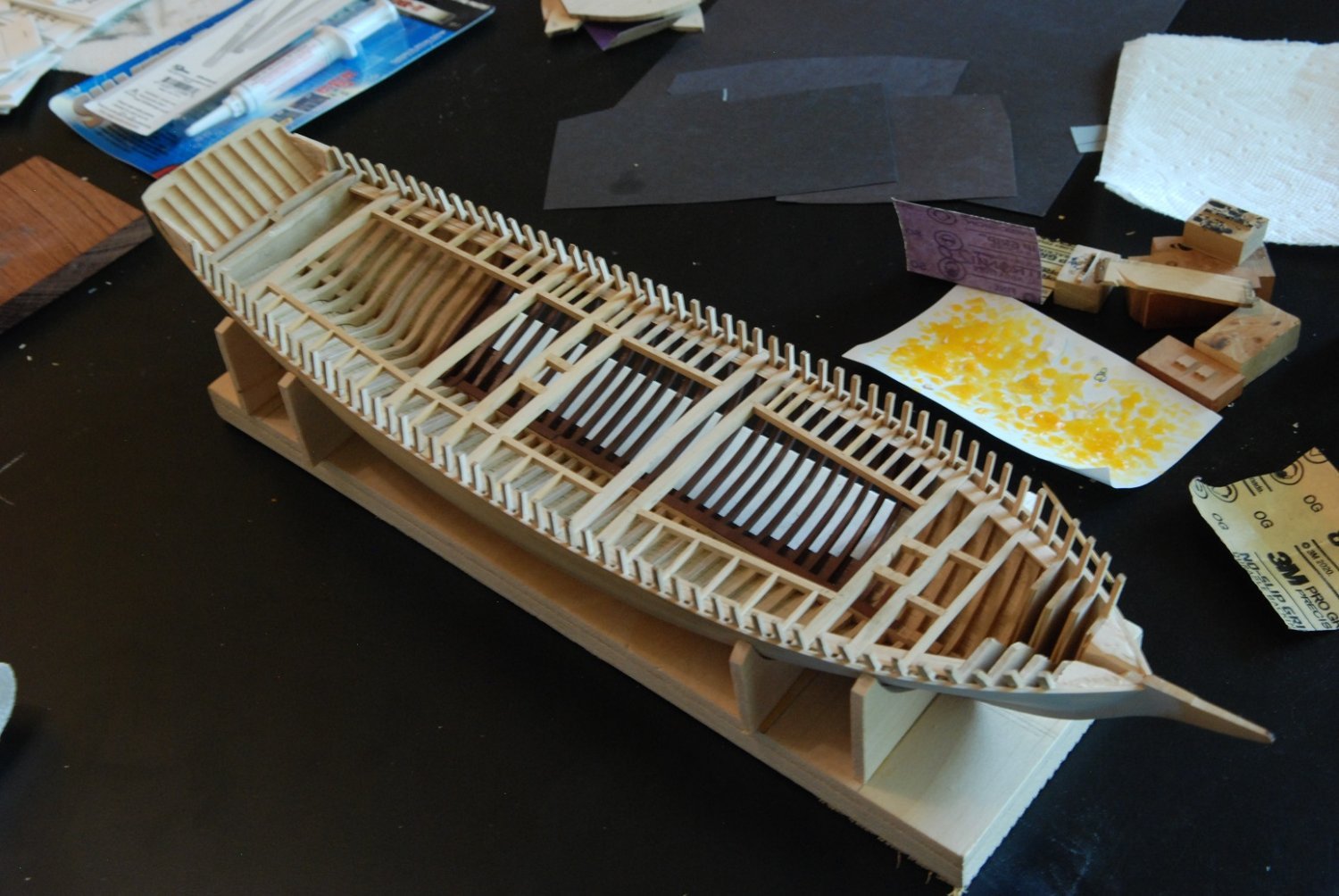
The unpainted ledges indicate where the planking will cover.
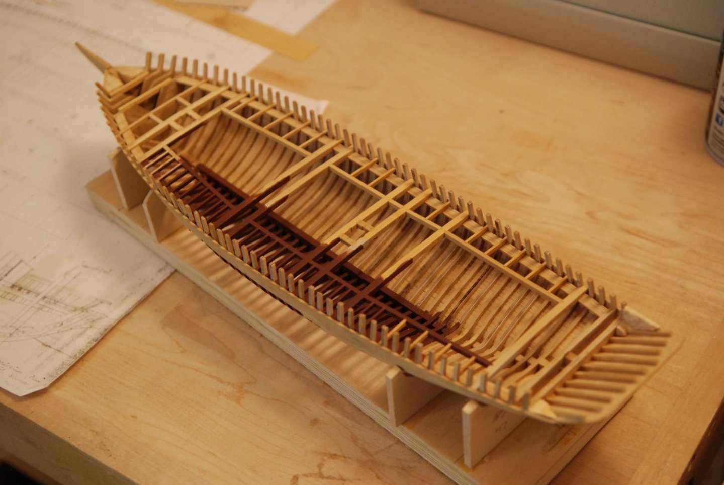

All painting and installation is complete.

Several spalls were added to two forward bulkheads to provide support for the deck planking in the bow. This area was also sanded with coarse sandpaper in an effort to start the deck fairing process.
That was very satisfying! And even more exciting will be when the deck planking begins to take shape. But at the same time, I am obsessing about fabricating the covering boards, which are very complex and delicate in shape. Next post!

- berhard, MEDDO, Paul Le Wol and 11 others
-
14
-
I think full-size cabinetmakers would be jealous of what you have been able to accomplish with the binnacle and belfry. Not to mention the ship's wheel!
- Gahm, Keith Black, mtaylor and 3 others
-
6
-
Absolutely spectacular! Initially I did not understand the threading of the serving line through the eyebolts but after further study it makes sense. Very good job of figuring out the necessary order of events to end up where you did.
- Keith Black, archjofo and druxey
-
3
-
I am appreciating the tutorials in nautical French!
- Keith Black, dvm27, archjofo and 3 others
-
6
-
While you might not have meaningful pictures of the original model, the rest of us now have meaningful pictures of the definitive model!
- archjofo, AJohnson, Keith Black and 7 others
-
10
-


Schooner Mary Day by jdbondy - 1:64 scale (3/16" to 1 foot)
in - Build logs for subjects built 1901 - Present Day
Posted
Margin planking has been installed on the port side!
This is very exciting because once I am finished with the margin planks on the starboard side, full deck planking can proceed rapidly (with a deck framing reveal on the port side).
As you can see, some repainting of the deck framing that will be revealed is in order.