


jdbondy
-
Posts
334 -
Joined
-
Last visited
Content Type
Profiles
Forums
Gallery
Events
Posts posted by jdbondy
-
-

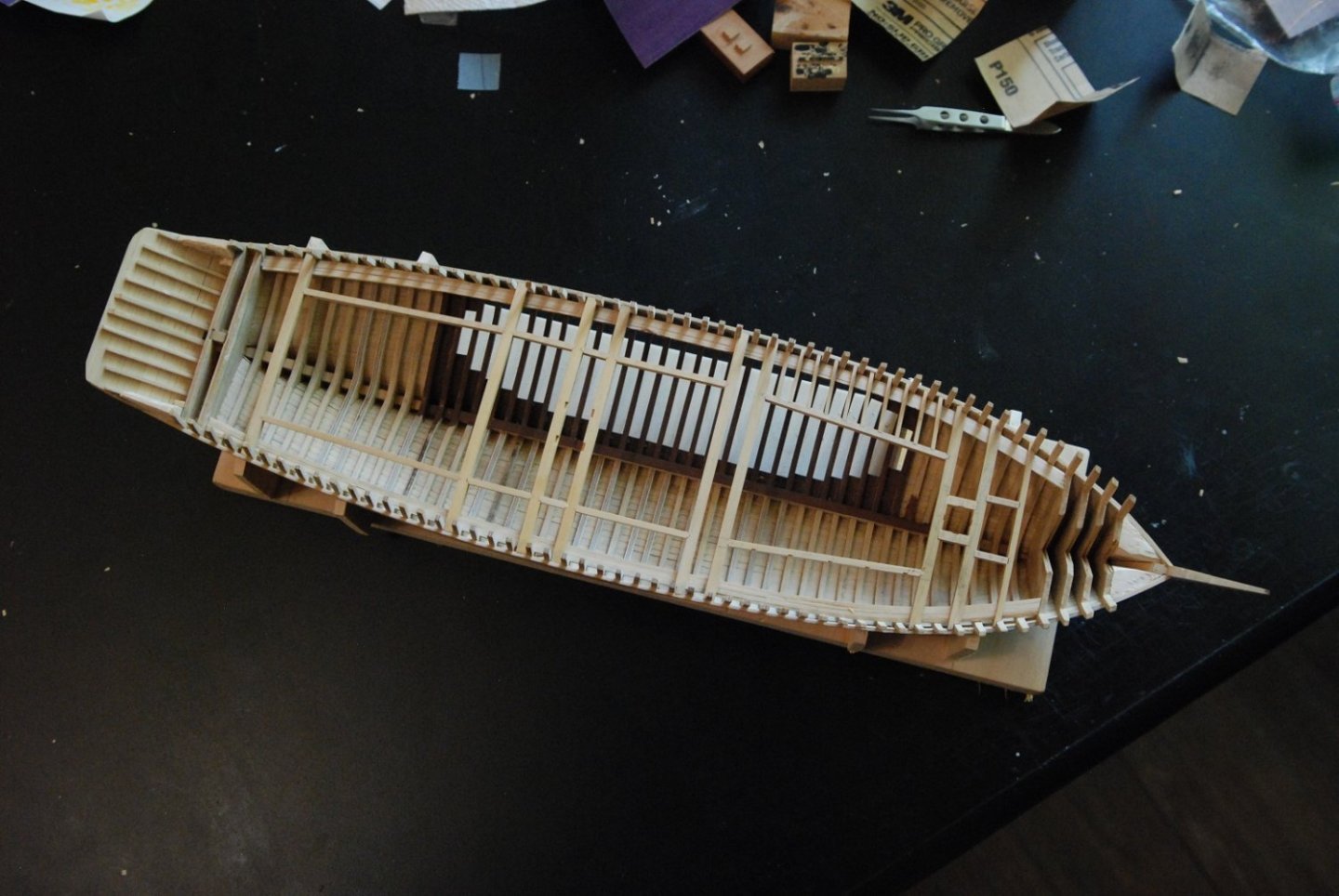
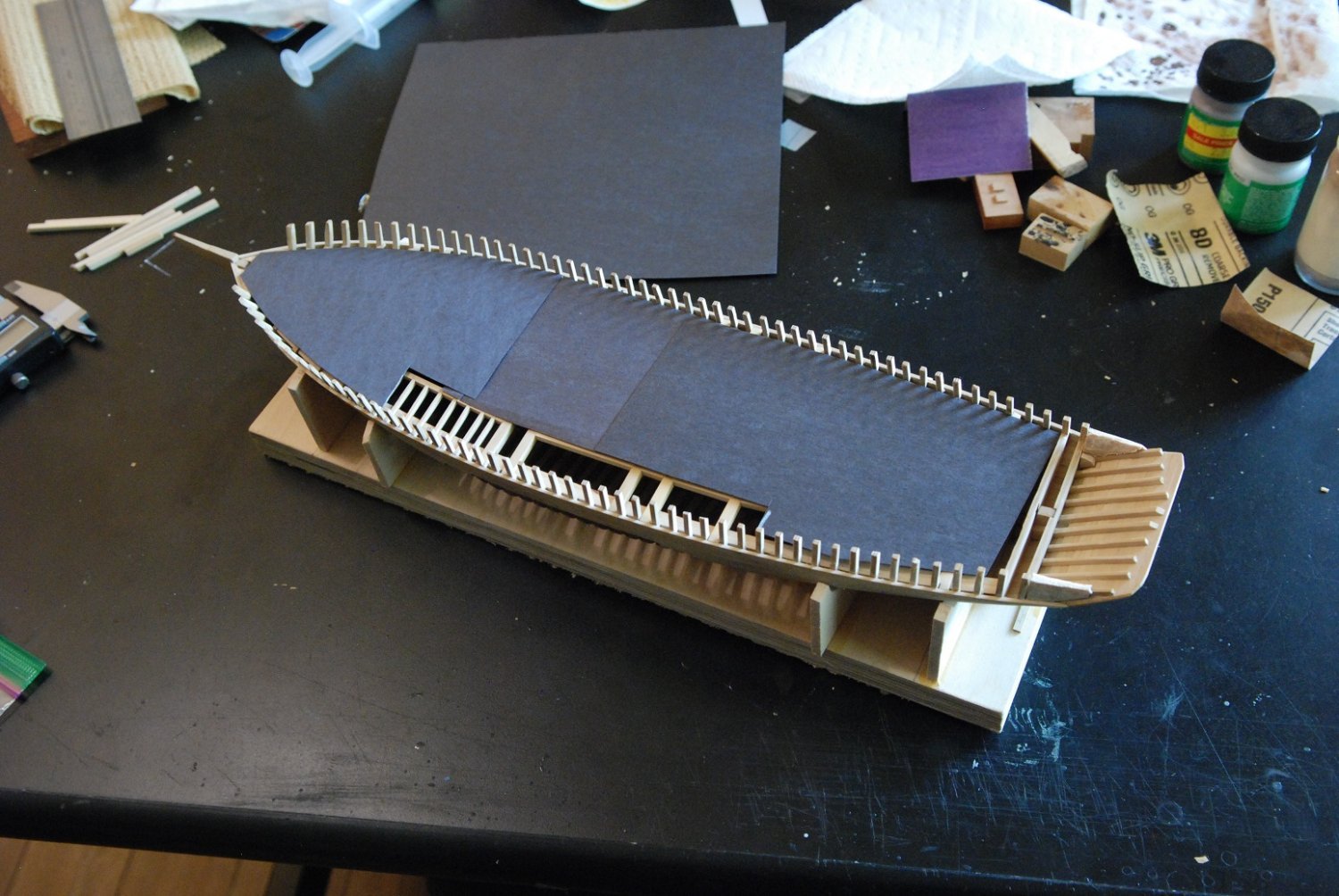
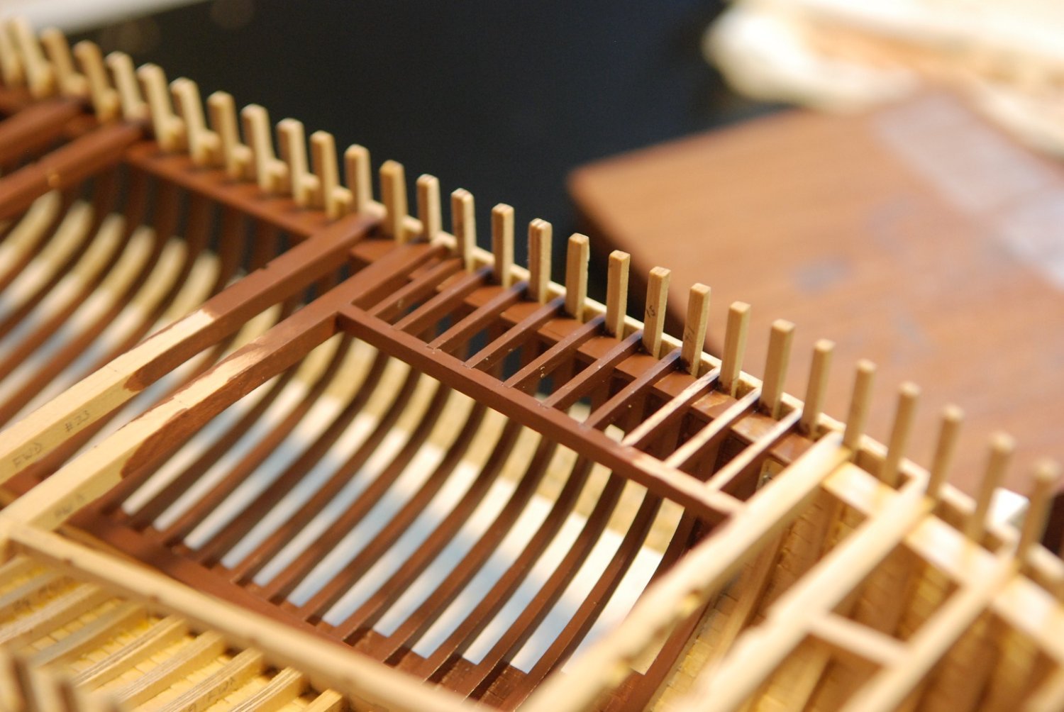
Time to start building the deck structure, which will help solidify the sides of the hull. I had been thinking about installing temporary spalls, but the shape of the hull seemed very stable without them and it didn’t seem to change much when I was fitting the deck beams at the point of maximum beam.
I made a pattern template for the curvature of the beams to match the camber of the deck on the actual ship. On one of my visits to the Mary Day, I strung a string from one side to the other at the point of maximum beam, secured with tape to a stanchion on each side. I then dropped the string on each side until it barely touched the deck in the centerline, then measured the height at each stanchion. The rise in the centerline was 4.5”. I then used the method described by Chapelle in his Boatbuilding text to draw out the appropriate curve on cardstock. Which is challenging to do at this small scale. This was then transferred to a piece of wood for additional stability.
Some of the beams were made with Castello boxwood, while I started to splurge with some English (Buxus) boxwood for some of them so I could see if it was noticeably different from the Castello. The pattern was transcribed onto stock of appropriate thickness, for both the upper and lower surfaces of the beams. Multiple pieces of appropriate length were created, and the center point on the curve was also transferred to each piece.
The joint of each beam with the planking and each beam shelf was often very complicated and called for a lot of trial fitting. Trimming at each end was very gradual and symmetric in order to try to preserve the position of the centerline marks.

There were multiple facets of the joints that had to be trimmed in a symmetric fashion, as the beams articulate with not just the beam shelf but also with the frames themselves.

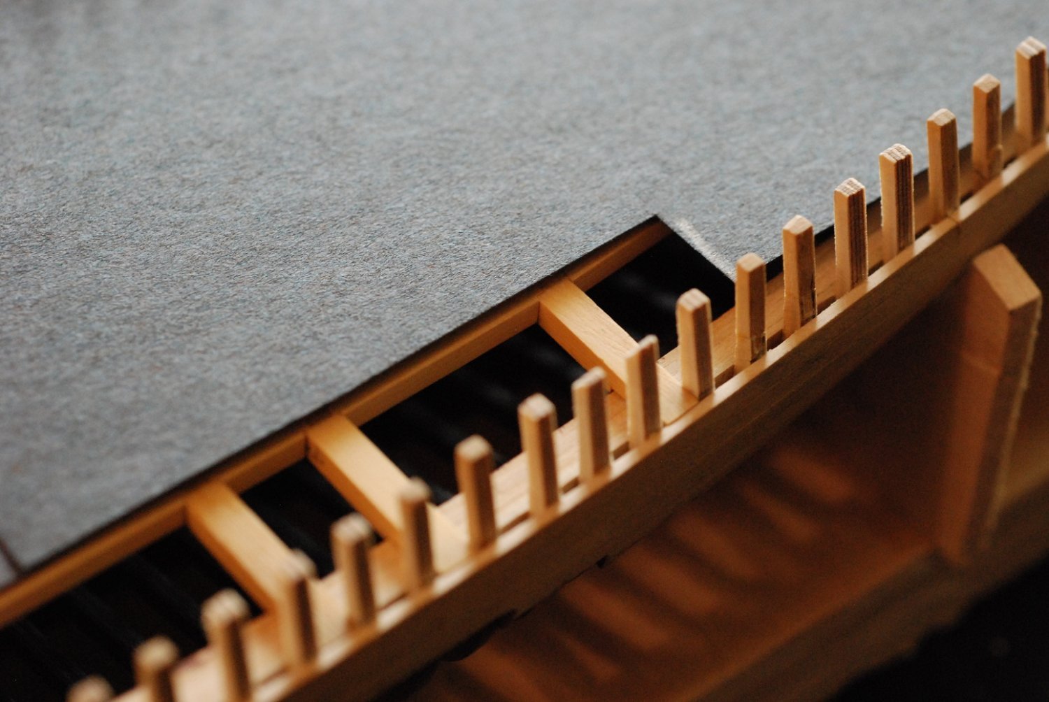
This beam is almost completely flush with the sheer strake.
A lot of work just to install the eight deck beams, and that was after I decided to neglect some beams normally found near the stern.
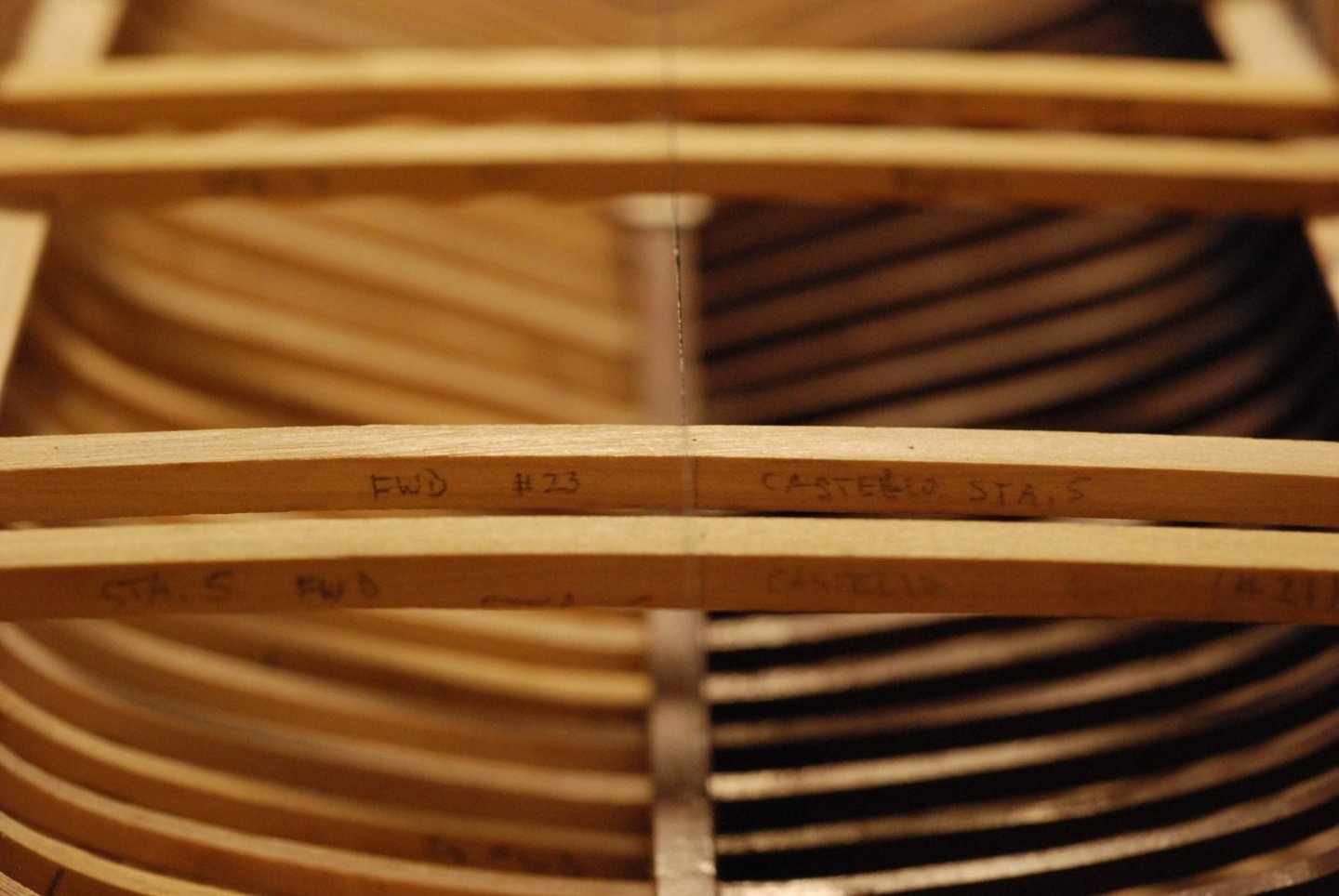
These Castello beams have their center points marked. There is a fine thread strung from stern to stem, and it appears that they don’t quite line up. The difference is about 1/32”. I am thinking that the stem may be leaning to one side a tiny bit.
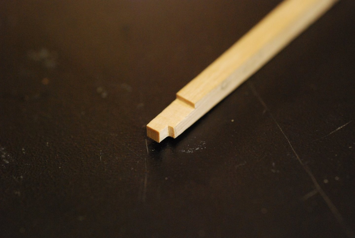
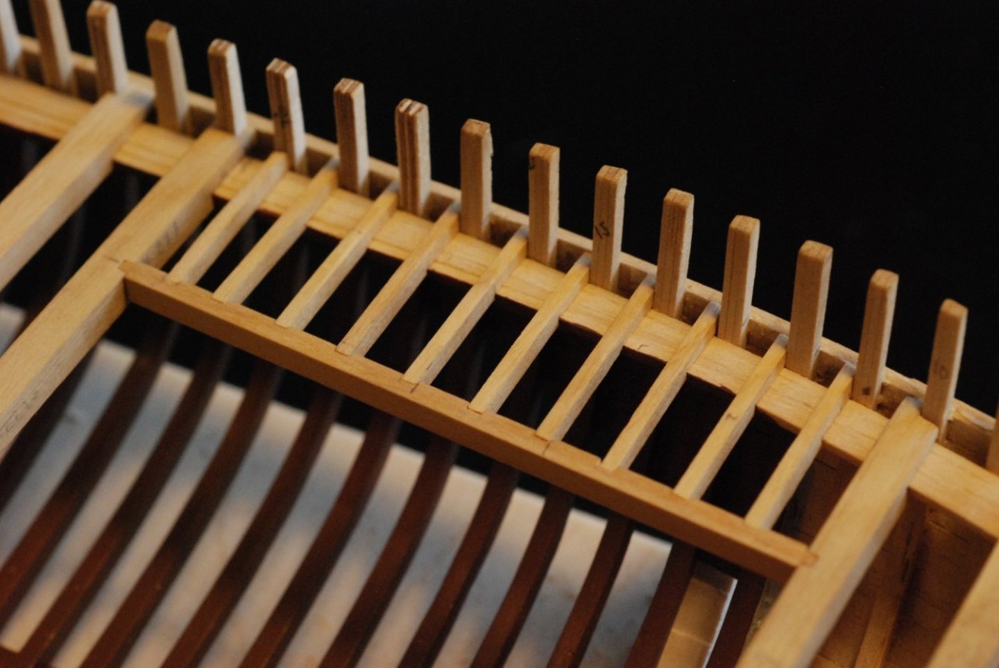
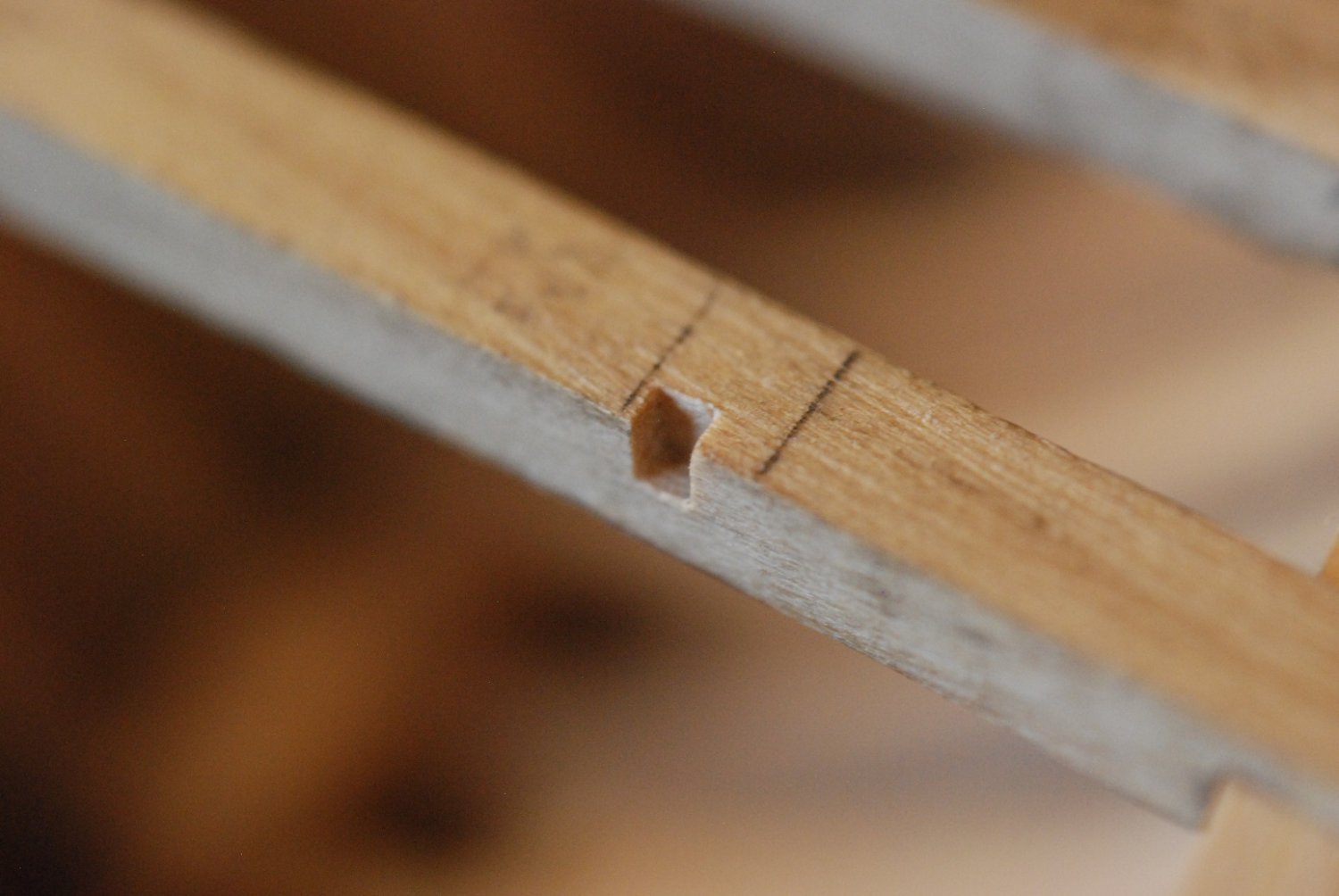
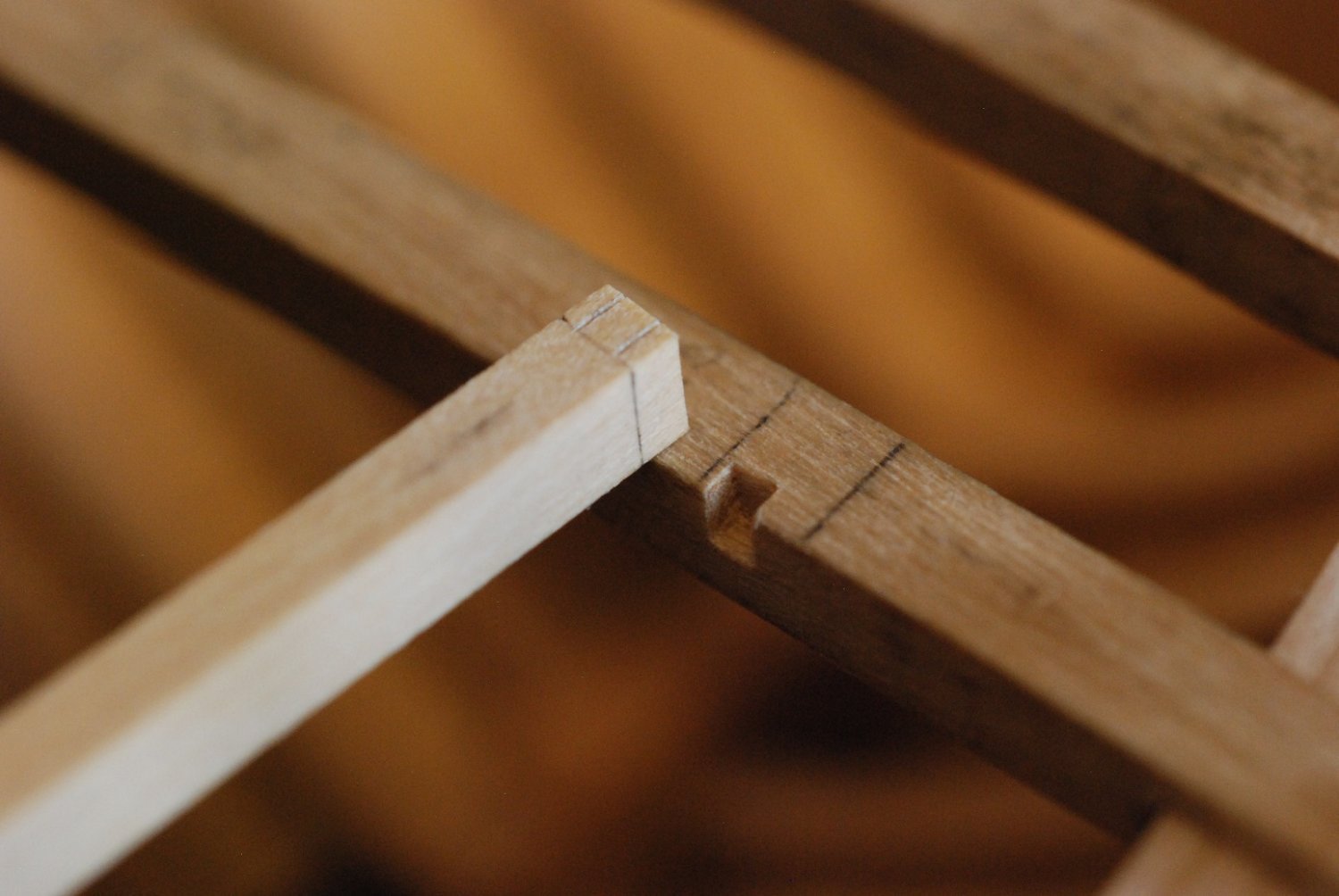
Next up are the carlings that make up the support for the deck houses. This will be my first opportunity to cut joints. The plans indicate dovetail joints, but I decided to cut square joints.
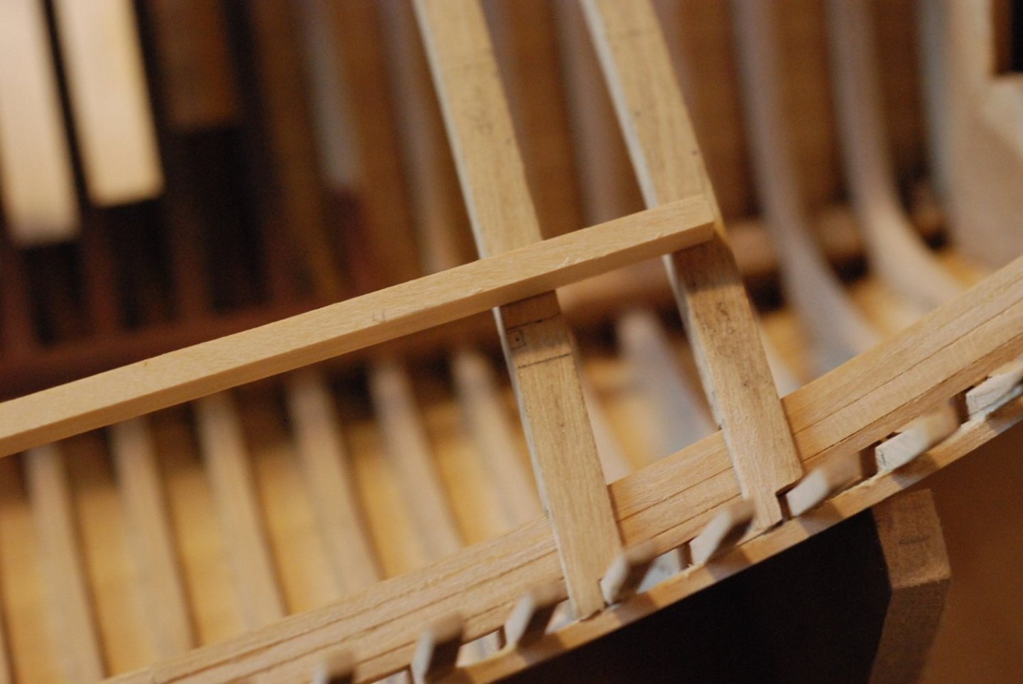
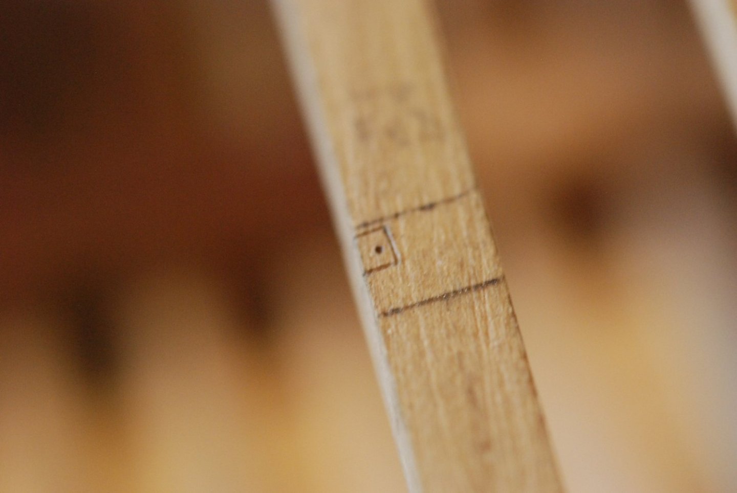
Marking off the joint locations and cutting the carling to length.

The microscope was a huge help in cutting these joints.

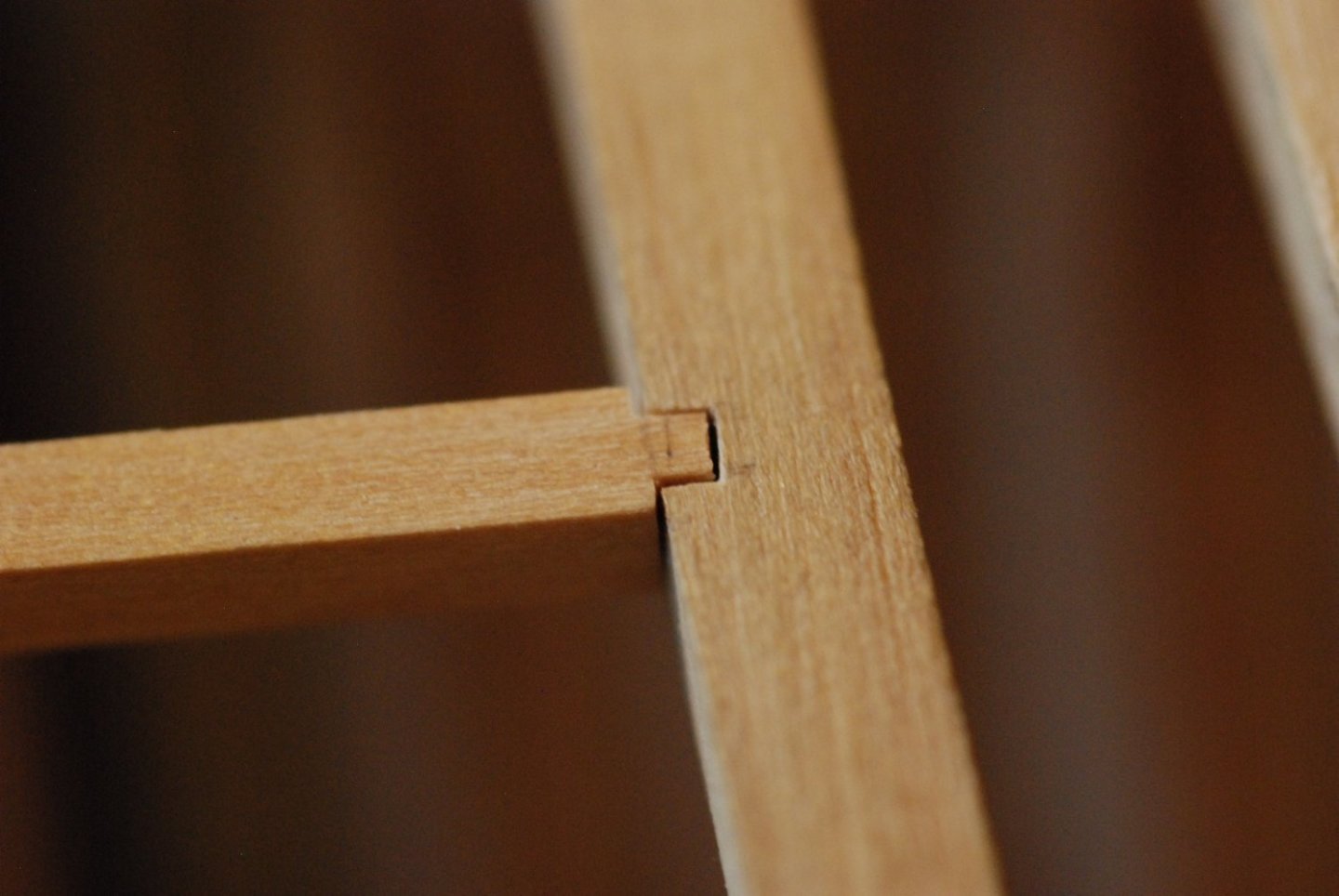
This joint actually has a bit more of a gap in it than I was shooting for. But overall they made for a very rigid deck structure, and it was a very satisfying process.

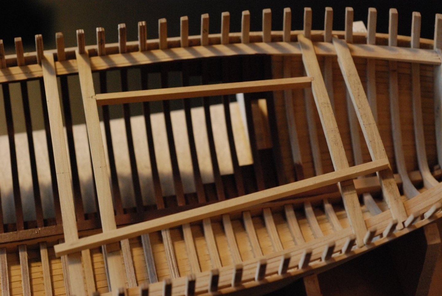
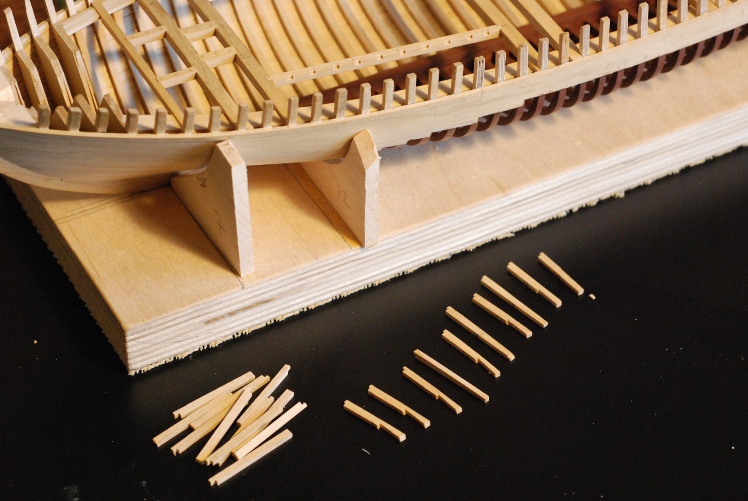
Time for the ledges. In the areas of the deck that are to remain unplanked, all of the ledges will be installed. But in the areas to be covered over, I decided to install every other ledge.
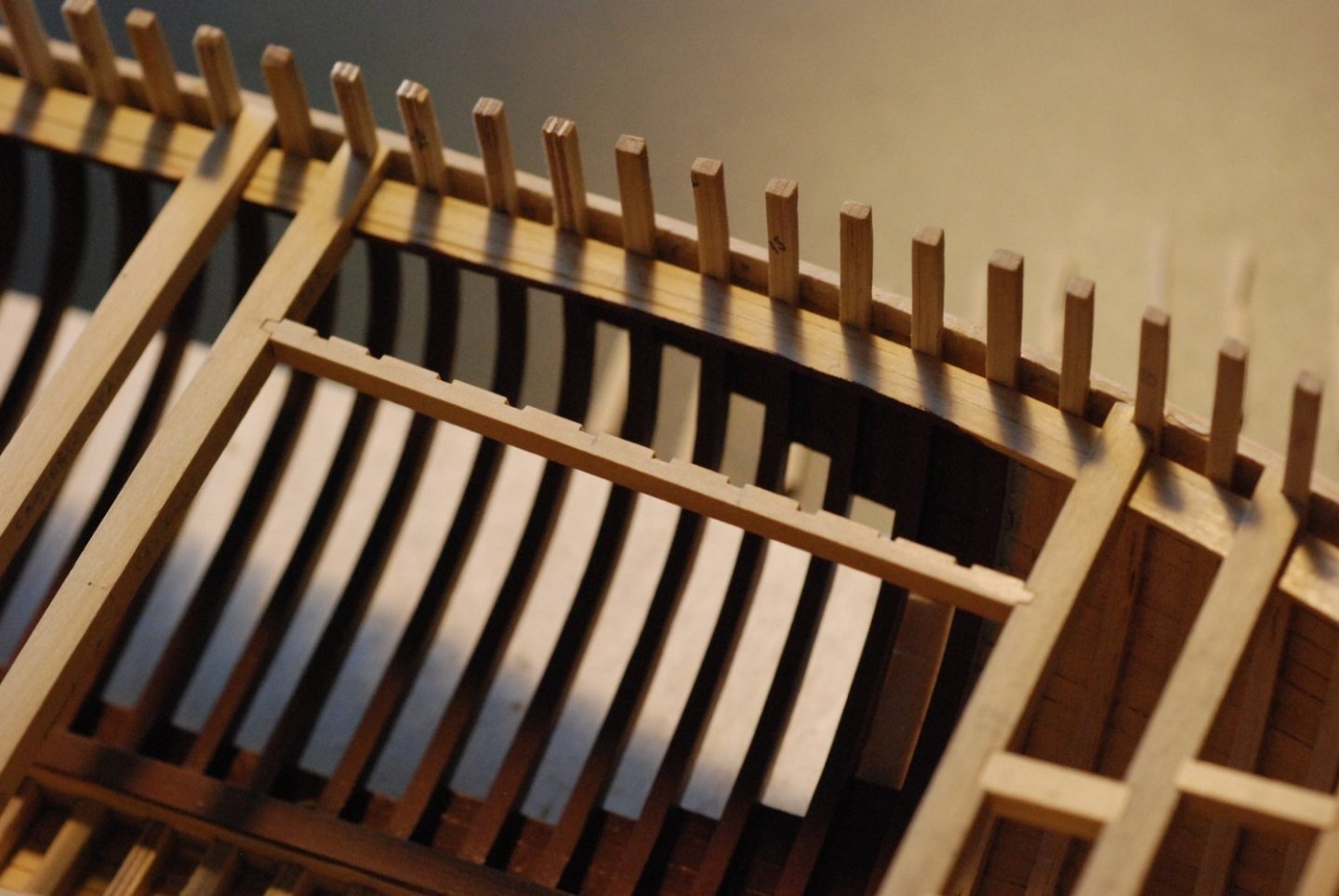
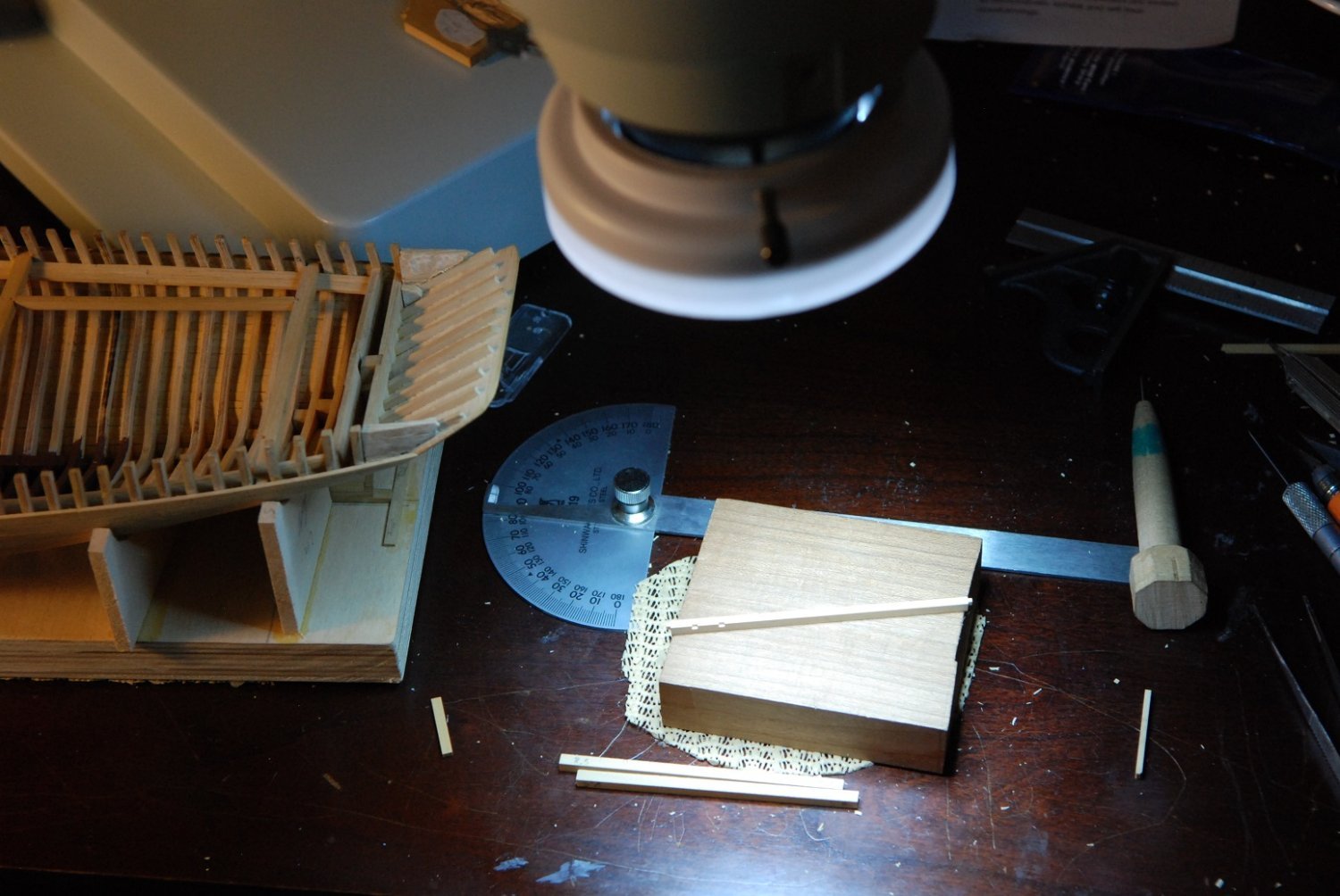
This particular carling was a lot of work, with ten joints in it. Each had to be placed accurately, so that the ledges would stay parallel and would articulate properly with their corresponding frames.

Due to all this trial and error, I set the model right next to where I was cutting the joints under the microscope so I didn’t have to keep getting up from the microscope and go back to the workbench.
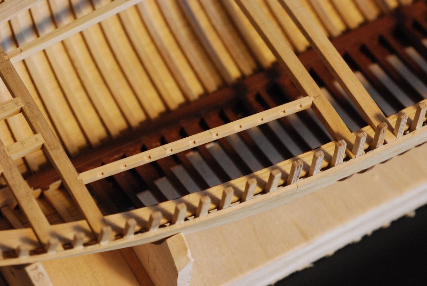
Each ledge was of course unique, as they had to be of the proper length, they had to have proper camber, and they had to be notched on the underside to articulate with the beam shelf.

Port and starboard side surrounding the forward deckhouse is done. Also installed are coamings for a forward hatch, as well as the mast partners.

Now moving towards the stern, with all but one carling trimmed to length and installed.
All carlings cut to length. But not glued in place yet, until I was satisfied with how everything articulated.

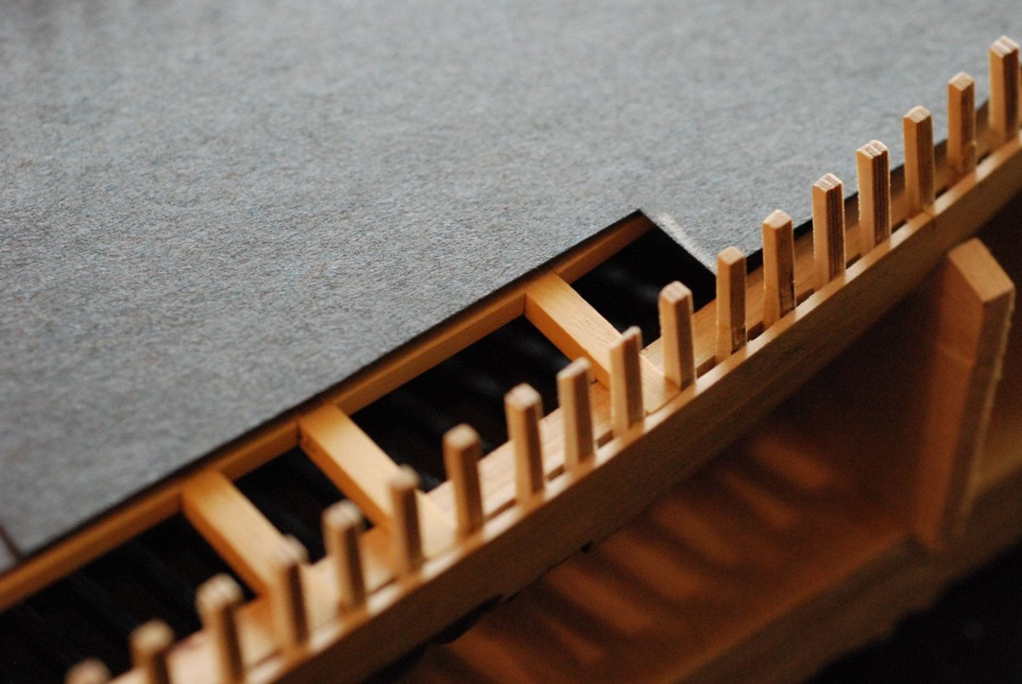
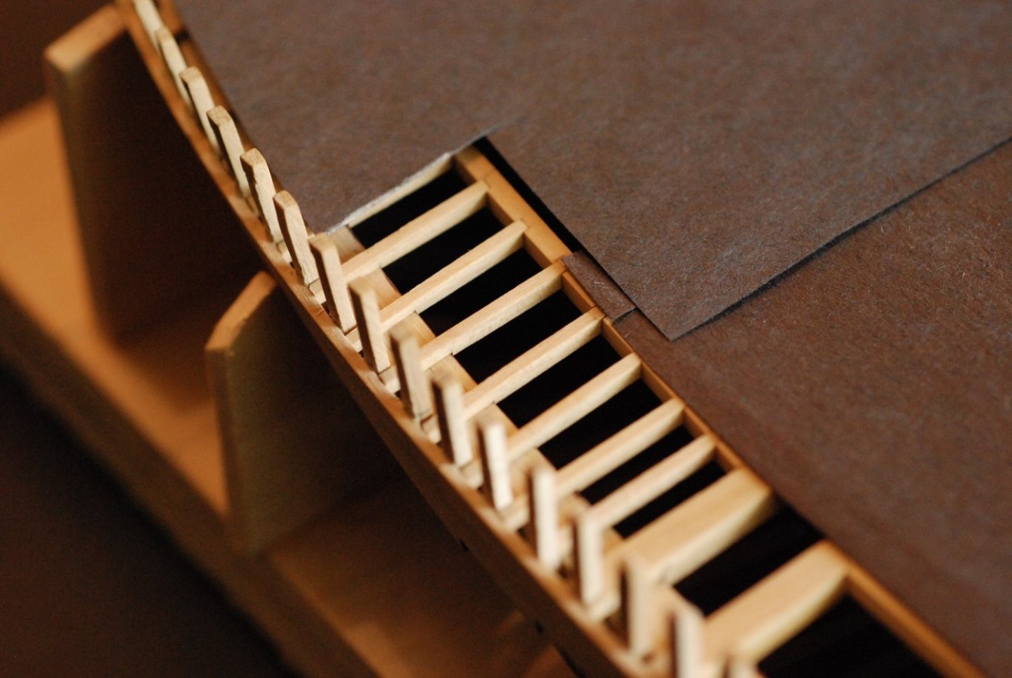
In order to make sure that I painted all interior areas that would be visible following deck planking, I covered the entire deck with the exception of the area that would remain unplanked, then visually inspected the interior. Fortunately it looked like everything was covered.
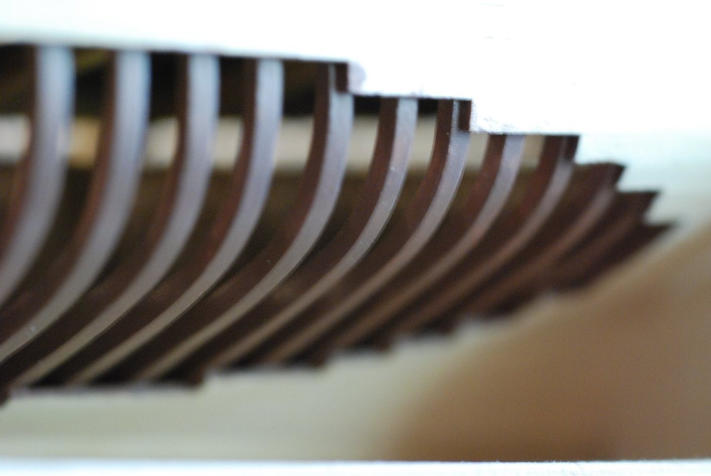
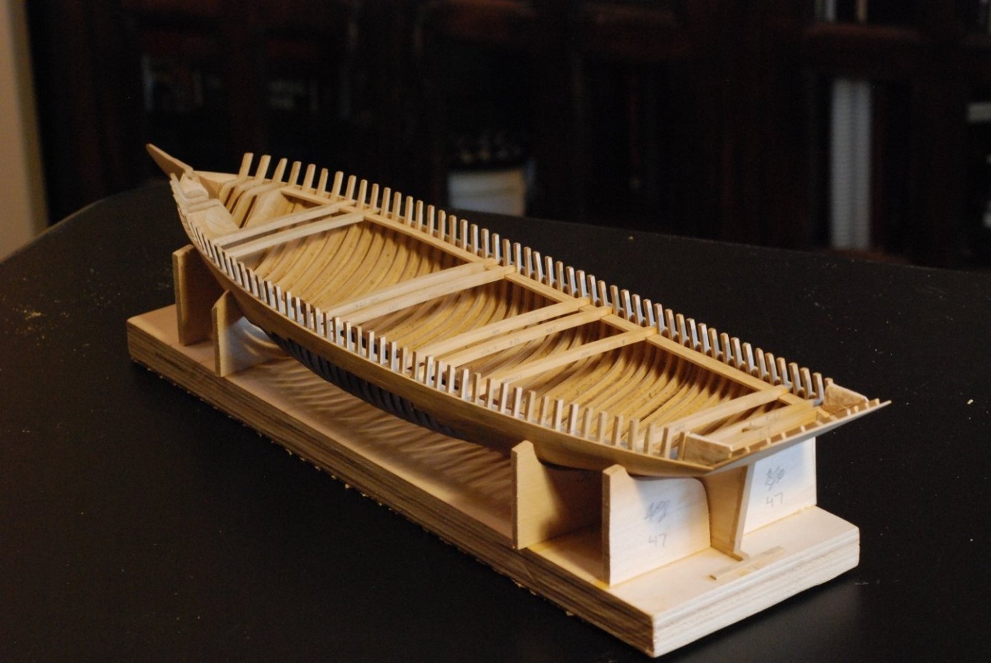
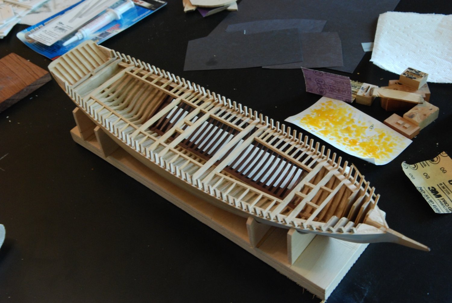
Pretty happy with how the frames have turned out.
Painting this area accurately will be tricky, since I will want the exterior surface painted accurately, but the cut surfaces of the planks will need to be brown.
All beams, carlings, and ledges were dry-fitted to make sure everything is shipshape. Then, the ledges in the area that will be exposed were removed and everything else was glued into place.

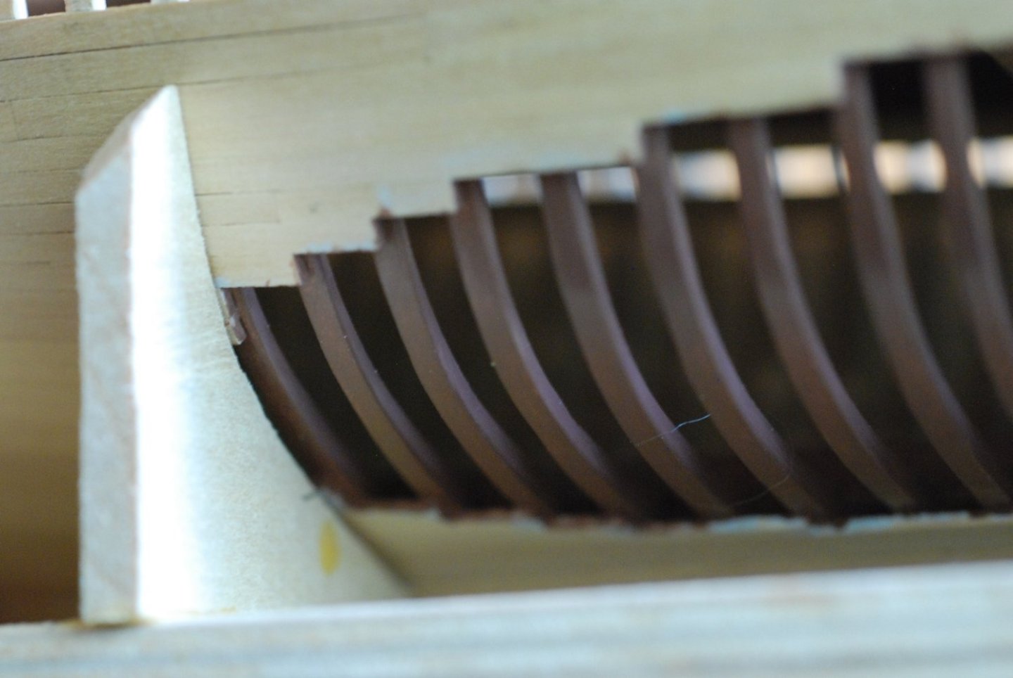
Before painting the areas that would remain exposed, I addressed cutting down these two bulkheads at the stern to appropriate height. The more forward of the two was marked using a template of the deck camber.
The excess was carefully chiseled away to allow for a fair run of planking as dictated by this batten.
Painting of the exposed deck structure was then performed. The beams and carlings were painted, sanded, and re-painted while in place. The ledges were painted to appropriate smoothness prior to installation.

The unpainted ledges indicate where the planking will cover.

All painting and installation is complete.

Several spalls were added to two forward bulkheads to provide support for the deck planking in the bow. This area was also sanded with coarse sandpaper in an effort to start the deck fairing process.
That was very satisfying! And even more exciting will be when the deck planking begins to take shape. But at the same time, I am obsessing about fabricating the covering boards, which are very complex and delicate in shape. Next post!

-
I think full-size cabinetmakers would be jealous of what you have been able to accomplish with the binnacle and belfry. Not to mention the ship's wheel!
- Keith Black, scrubbyj427, archjofo and 3 others
-
 6
6
-
Absolutely spectacular! Initially I did not understand the threading of the serving line through the eyebolts but after further study it makes sense. Very good job of figuring out the necessary order of events to end up where you did.
- archjofo, Keith Black and druxey
-
3
-
-
While you might not have meaningful pictures of the original model, the rest of us now have meaningful pictures of the definitive model!
- Gahm, Keith Black, mtaylor and 7 others
-
10
-
-
Question for you Matiz: the main rail of the head has molding along its outside edge, but I don't see how that could be easily scraped in, since the rail is tapering along its length. How did you do that? Entirely manually?
-
I love how you work around the knots in the lumber to obtain pieces with grain direction that fits the shapes you need!
- Keith Black and matiz
-
2
-
Jeez, now I have to worm my lines prior to serving them?? Are you going to make me parcel them too??
- Keith Black, dvm27, hollowneck and 5 others
-
5
-
 3
3
-
-
Thanks Johann, you answered my question. But I will keep an eye on the continuing discussion with Greg since I am interested in that answer too!
- archjofo, FriedClams, Keith Black and 2 others
-
5
-
I have a question related to Greg's question above. You explained how you measured the needed length for the double strops on the block. But how did you create that continuous loop using served line? Did you serve the loop after it was created with the correct length of line? Did you use line that was already served, and somehow made a continuous loop out of it? Thanks.
- archjofo, FriedClams, mtaylor and 2 others
-
5
-
Let me echo Allan's question. Tell us more about the rope!!
- Keith Black, mtaylor and bruce d
-
3
-
-
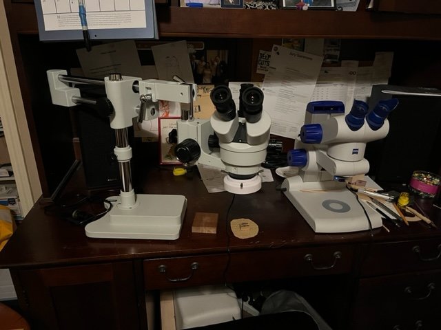
In general, you are looking for a stereo microscope. These use light reflected off the surface of a 3 dimensional object, as opposed to microscopes used for looking at tissues by transmitting light through a glass slide. The binocular vision of a stereo microscope allows that depth perception you referred to. In general, these kinds of microscopes do allow for enough working space between the object and the lens. In the case of my Zeiss microscope, I get about 3-4 inches of clear space between the surface of the object and the lens. Plenty of space for my small chisels. This space is not affected by how much or little I zoom in on the object because the zooming mechanics are within the microscope. The eyepieces have a magnification power of 10x. Then, using the zoom, that magnification can be increased as high as 32x.
Since I just acquired the microscope you see on the boom stand, I am still learning it. Its magnifications are comparable to the Zeiss, with 10x eyepieces and zooming up to a magnification as great as 45x. But I can't see much of a difference between the 32x on the one and the 45x on the other. The new microscope has two advantages: one, a greater amount of clear space between the object and the lens (6 inches), and two, I don't have to remove my glasses to look through the eyepieces. Which has been getting to be a real drag as I go back and forth from under the Zeiss microscope to on the model. The clear space is again not affected by how much zoom I apply.
You will need to figure out for yourself if you need a boom stand. It's not essential for me; I simply steady the work with my left hand while carving with my right. I put a high-friction non-skid pad between the work and the base of the microscope (or the desktop). Or sometimes I am working on a piece that is fixed in a jeweler's ball vise.
Regarding dental loupes, I actually had a rep from a loupes company come to the house to try to fit me with loupes that allowed a long working distance. Nothing he had would provide the magnification I needed. I came to find that if I wanted really high magnification without using a microscope, I would have to do like the watchmakers and wear a watchmaker's loupe up against my eye, then bring the workpiece to within 1-2 inches of my eye. I wouldn't be able to work that way for very long.
I hope all this helps!
-
I have a Zeiss dissecting microscope that is intended for "student" use (probably students at a high-priced private school) that has been very nice. But it was expensive, even at a discount. Like $1000. I am now trialing a second microscope that I recently obtained second-hand that will have the capability for display on my computer's screen, once I figure out the software program. In general, a microscope has been key for enabling the kind of carvings you are now working on. Dissecting microscopes can be found on eBay starting at $100-200. I think that any average quality microscope will enhance your ability to generate fabulous small-scale carvings.
Photos of the two microscopes are attached.
-
Ben, a friend pointed me to your lovely build. I am now following along here, as well as on your Winnie build.
- mtaylor, druxey, FrankWouts and 1 other
-
4
-
-
I find myself sad that this chapter is coming to a close...but even more exciting chapters to follow!
- mtaylor, hollowneck, Keith Black and 3 others
-
6
-
-
Hi Gary, I was happily directed to this build log from a different log. I am making today's comment to make sure you are familiar with an article that appeared in the January/February 2023 edition of Wooden Boat, entitled "The Wizards of Stony Creek". It talks about Johnny Waters and his various boats (including oyster draggers) in the area of the Thimble Islands on the Connecticut coast. You seem to be someone who would be interested in the article. Enjoy!
- mtaylor and FriedClams
-
1
-
 1
1
-
Thanks, Druxey, Hubac, and Chris. Yes Chris, the manner was chosen because of the fact that at this scale, frames would be entirely too fragile to stand up to the planking process.
-
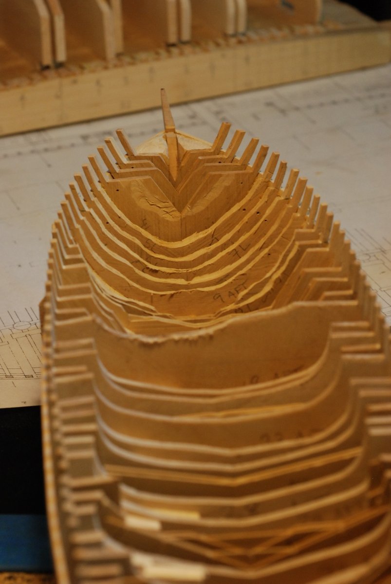
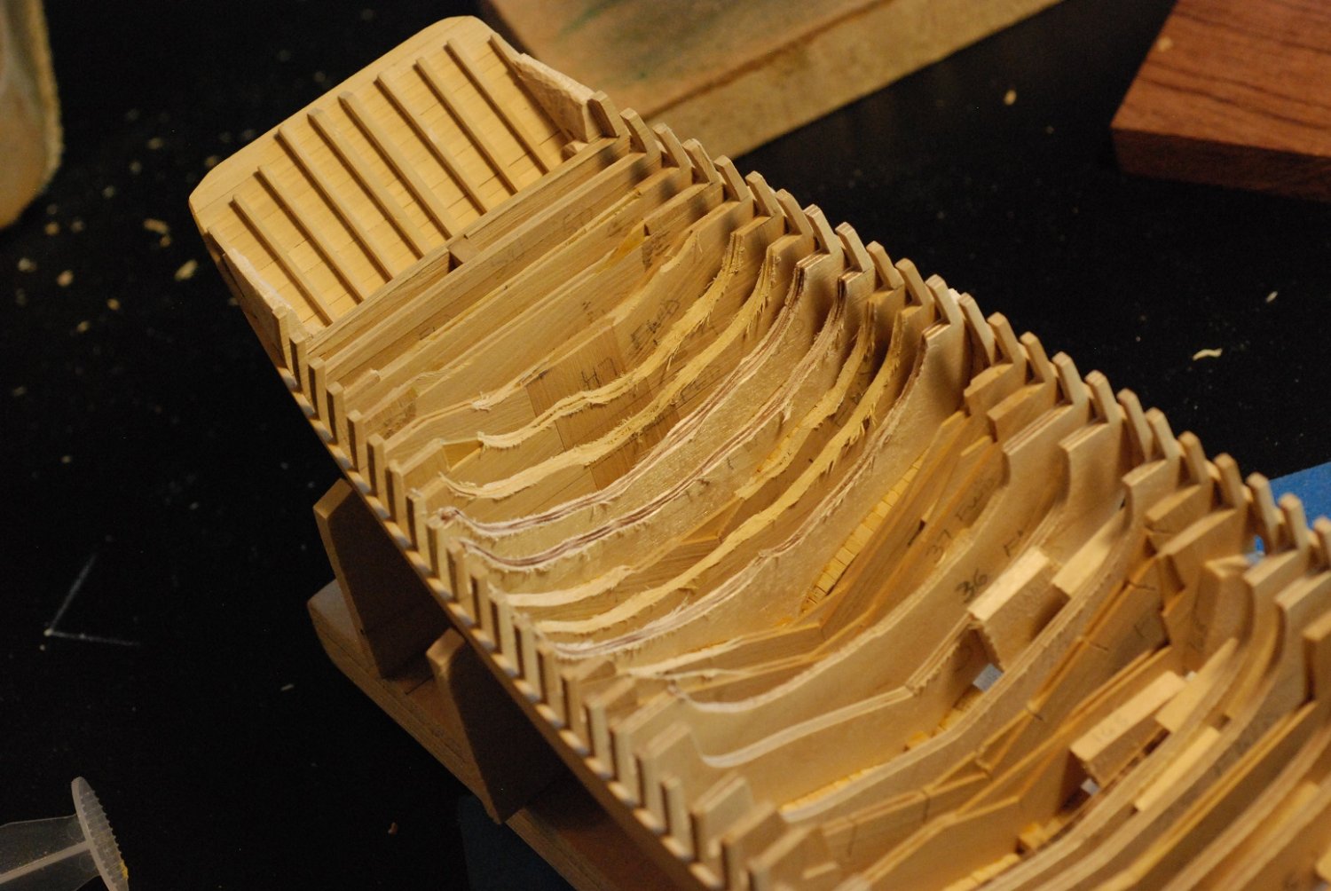
Wow, it's been 6 months since my last post!
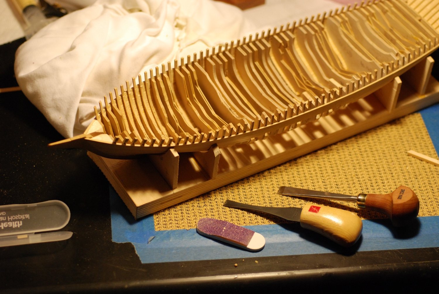
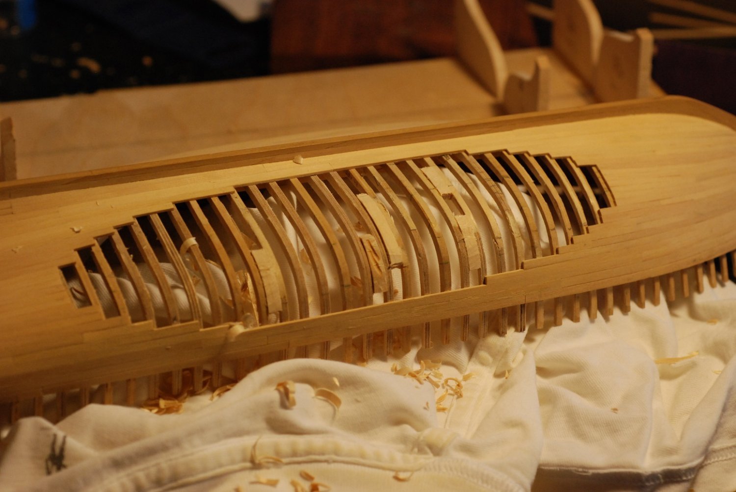
This next post is sort of a moment of truth. It’s time to grind out these numerous bulkheads down to forms that resemble the actual shapes of the interior framing of the boat. Which is no small task given the volume and number of these bulkheads. Numerous tools were considered for the job. The work in the above picture was done with the drum sander attachment to a Dremel.

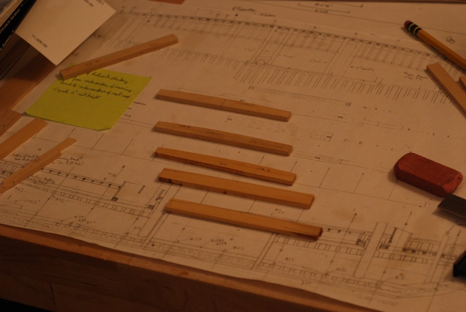
Here are some hand tools I tried, in an effort to see how safely and efficiently wood could be removed.

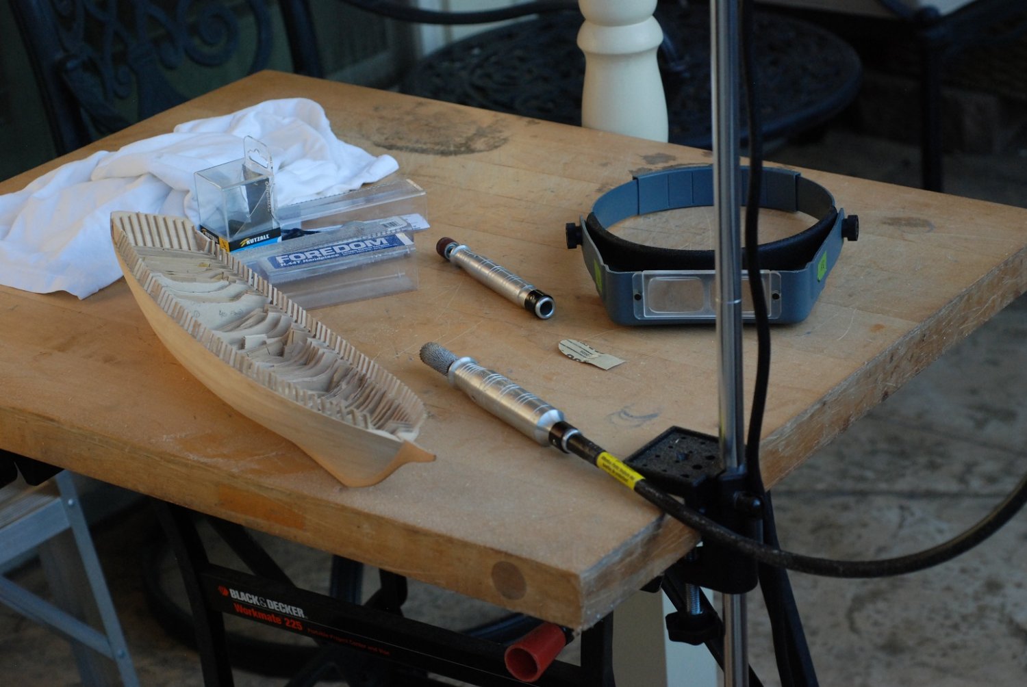
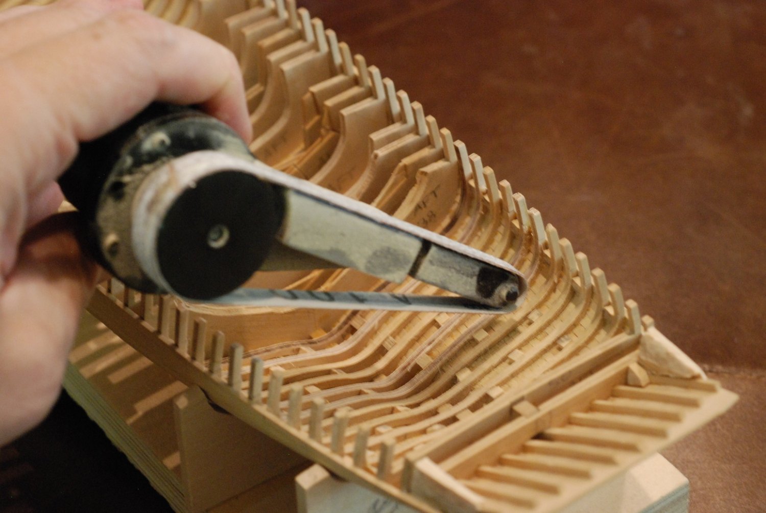
But it was pretty clear that the job called for more than just a Dremel. It was time to invest in a Foredom rotary tool. The Foredom is essentially the same kind of tool as a Dremel with a flex-shaft, but there are an amazing number of handpieces that can be attached to a Foredom.
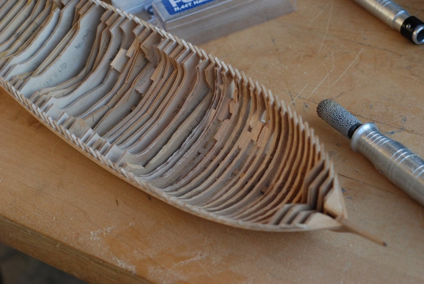
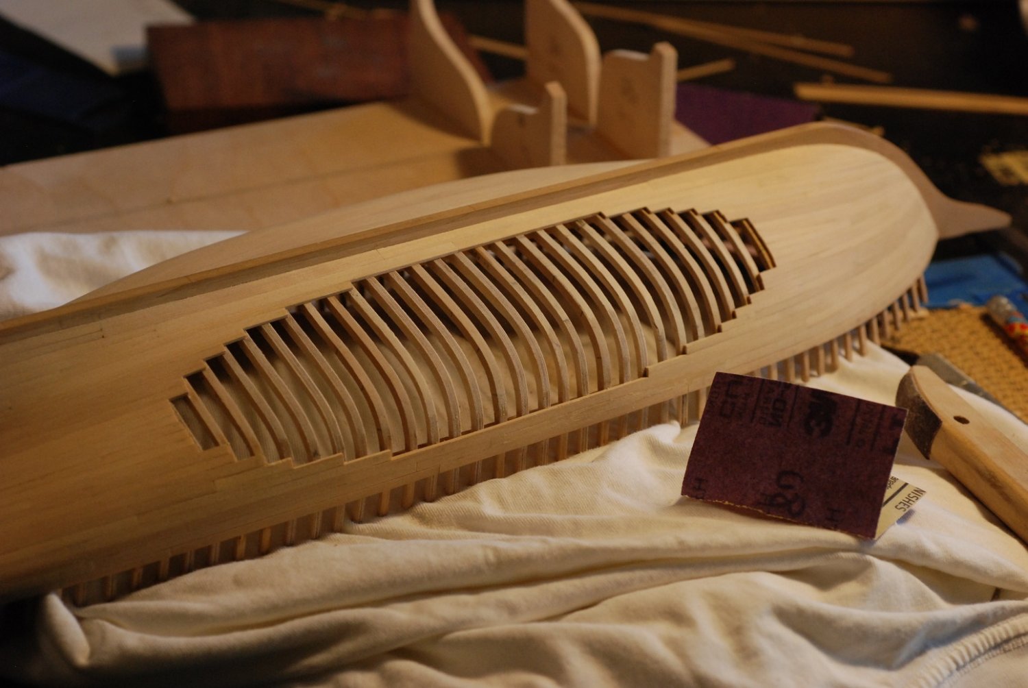
So I set up the workbench outside, with a hanging stand for the motor and a bullnose bit attached to the handpiece. This tool works very well and generates huge amounts of sawdust.
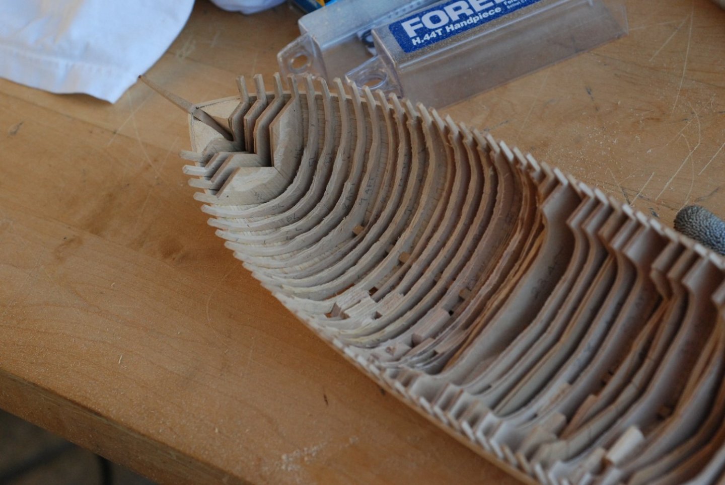
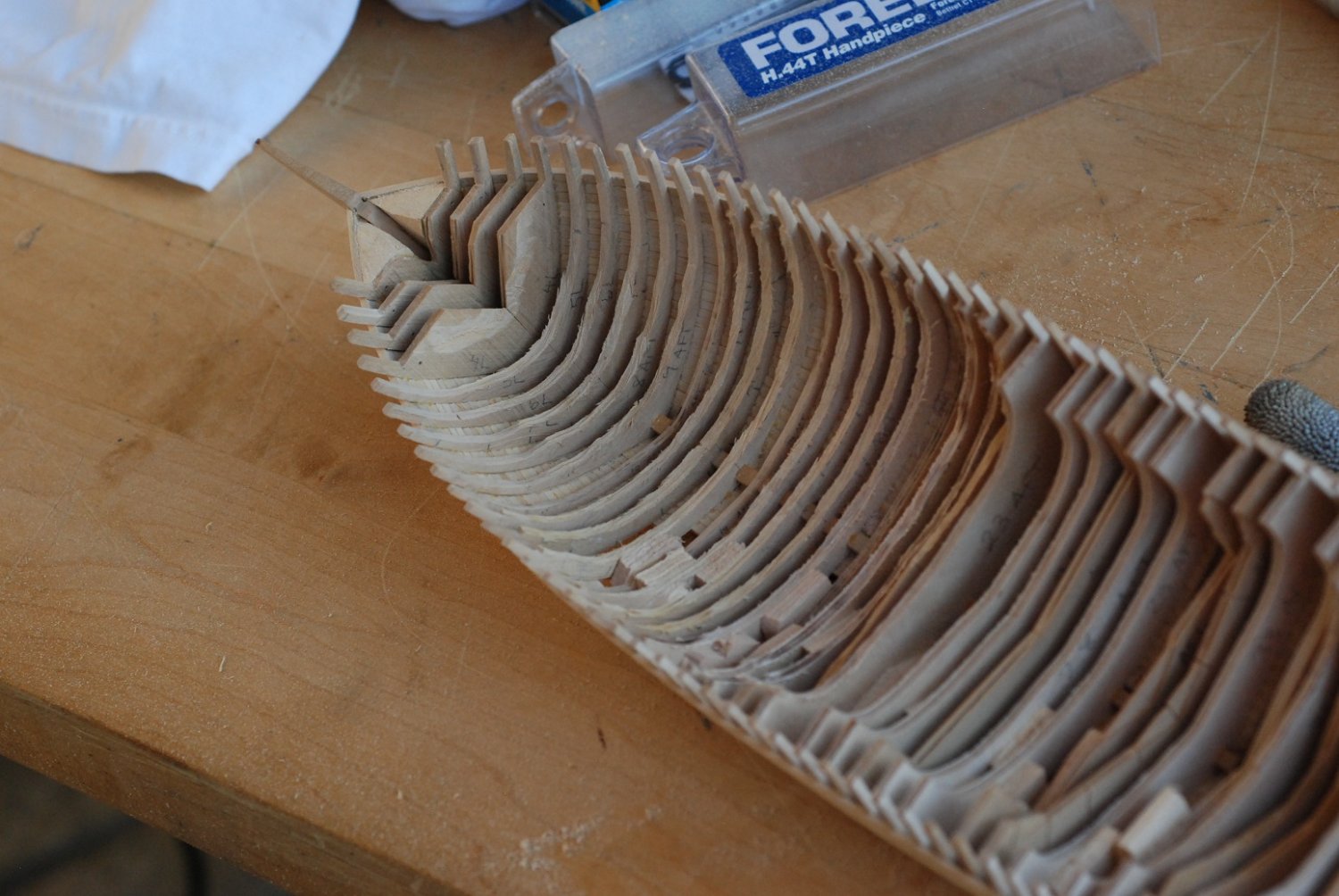
It makes quick work of grinding down the frames, but I had to make a deal with myself to only go so far with this tool. It could very easily do serious damage if I lost control of it.
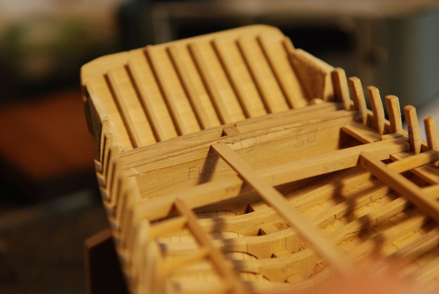
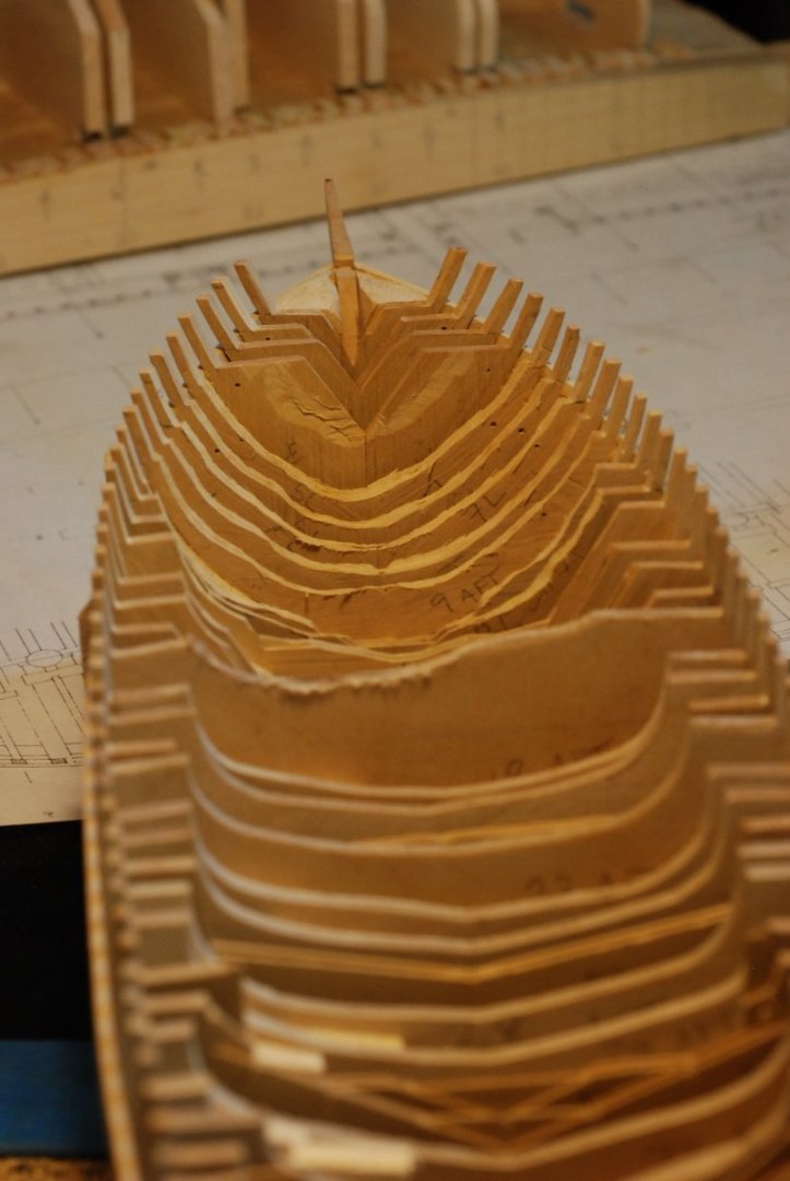
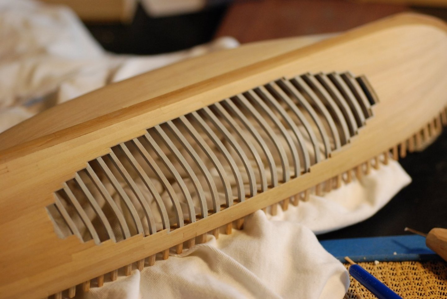
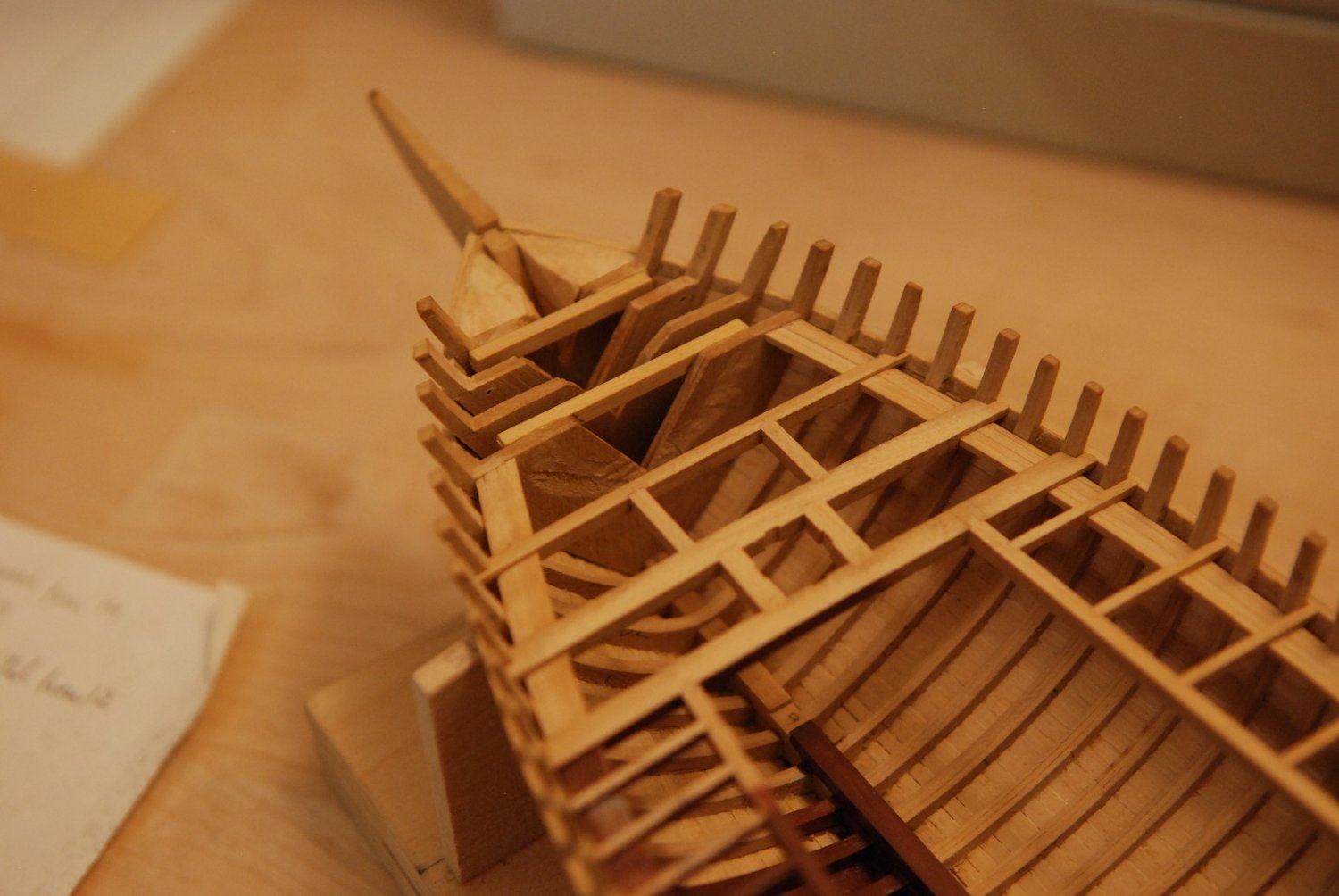
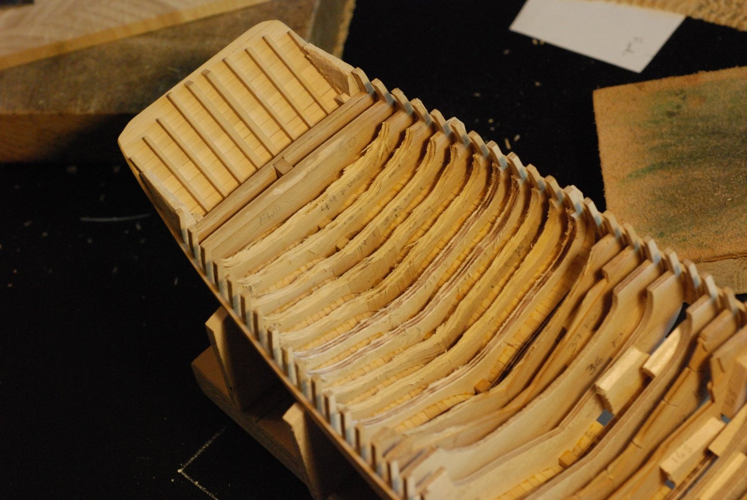
In the bow, there are four frames just aft of the bow filler blocks that I will not grind down.
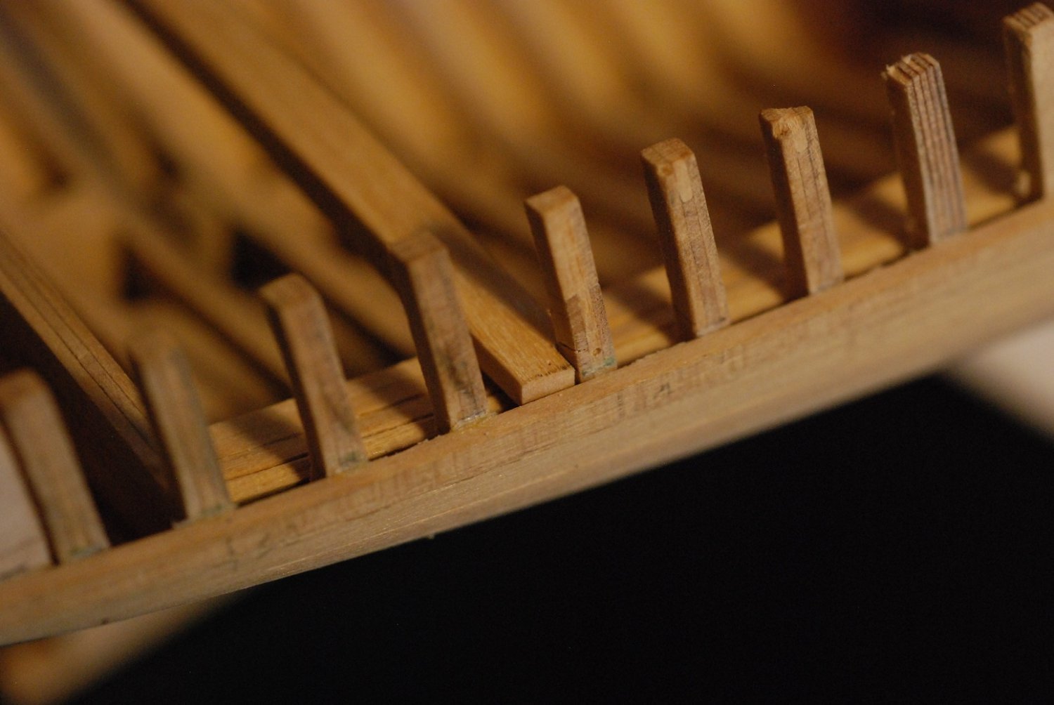
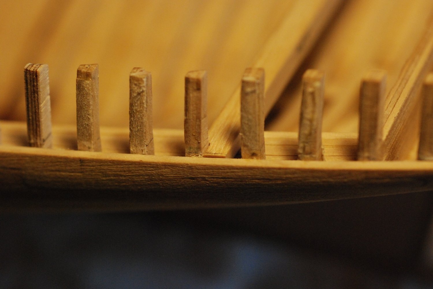
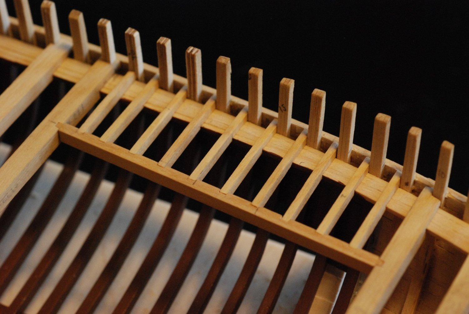
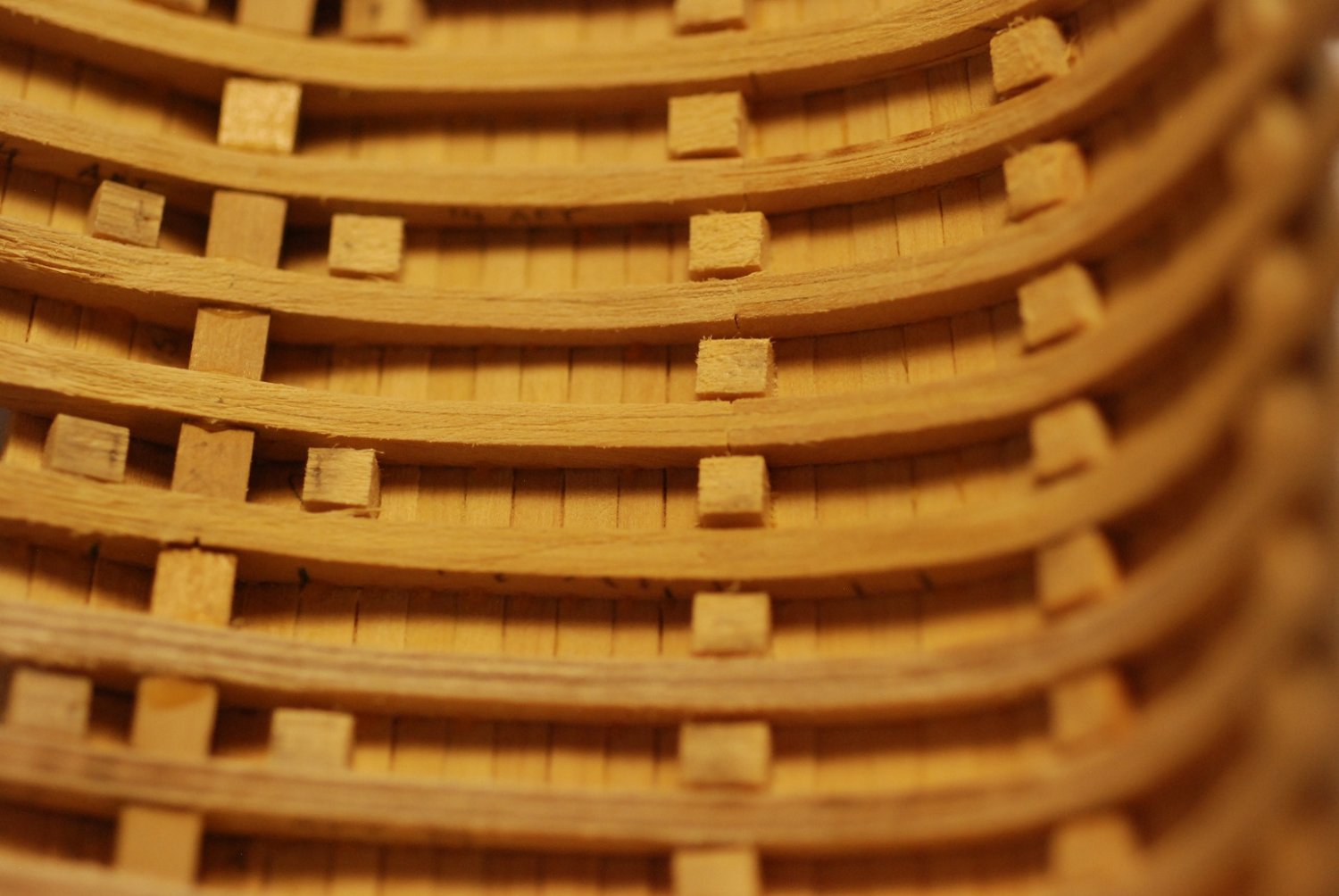
As a reminder, certain of the frames had been previously brought down to their proper molded dimensions, to serve as guides for future fairing of the frames between them. Three of these frames are visible here.
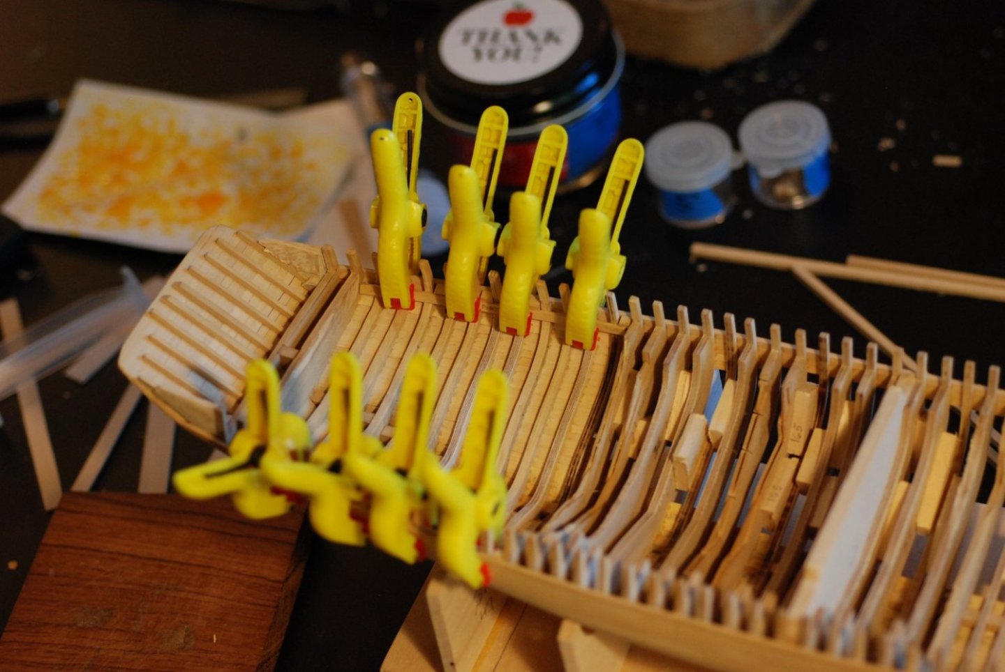
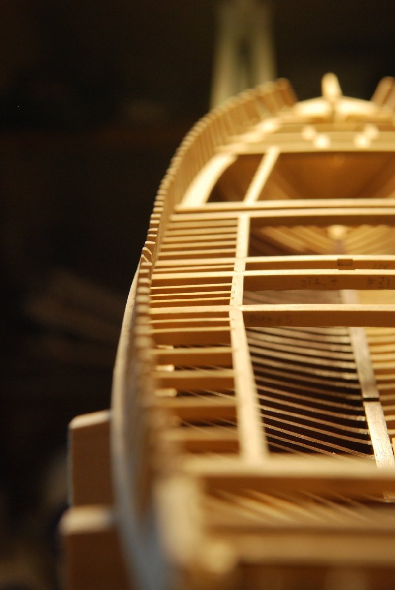
As I got closer and closer to proper molded dimensions, I decided to temporarily glue sacrificial blocks that were of the target thickness of the frames in those areas.
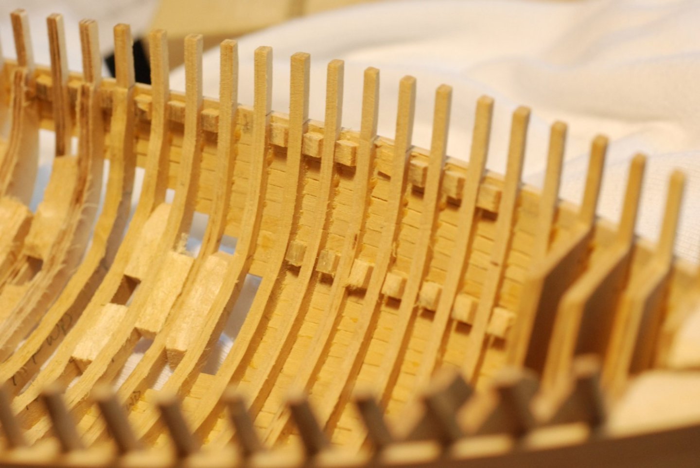
I could mark these with pencil and watch to see when I was starting to hit their surface in order to get an idea of when I was getting close.

Sort of like topography lines on a topo map, the blocks are lined up on the points at which each frame should have a certain molded dimension.
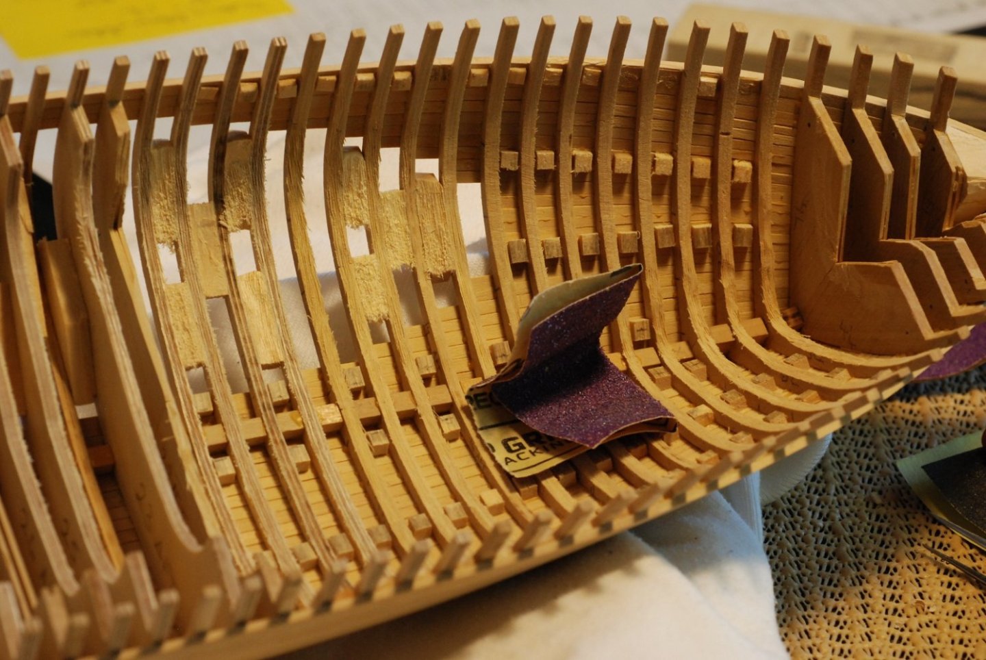
It was a lot of work bringing the frames down to their proper dimensions. Here I am using sandpaper to take off the really coarse marks left behind by the bullnose bit.


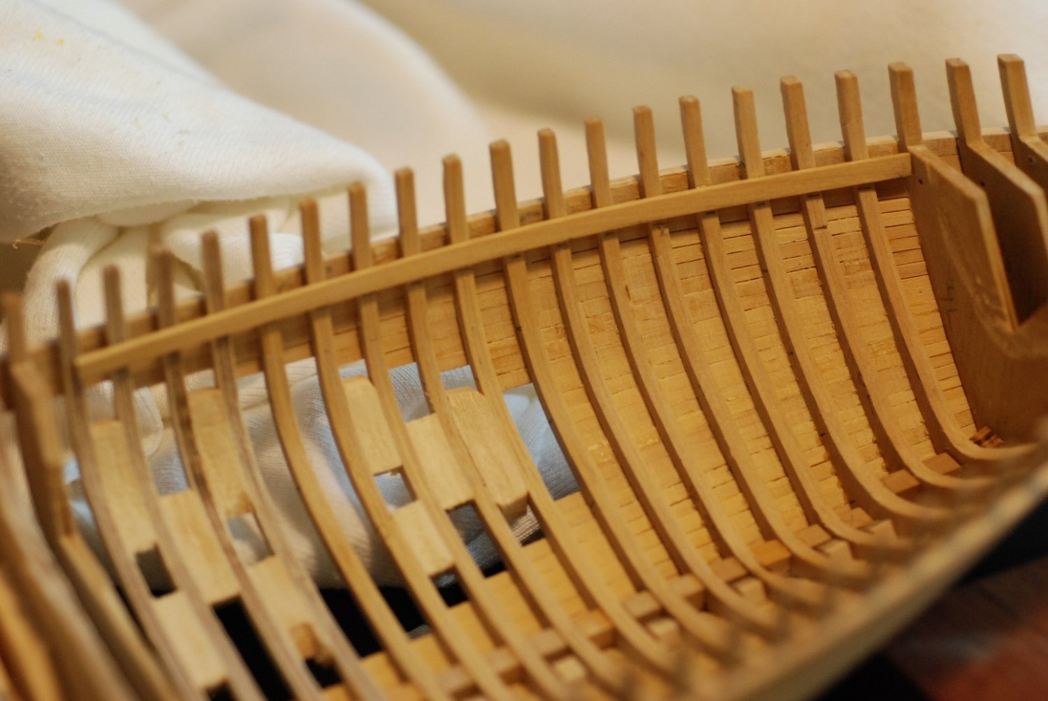
This was how I handled the forward third of the hull. In the middle third, I kept the bulkheads in place for the moment, because I wasn’t certain of the stability of the hull.

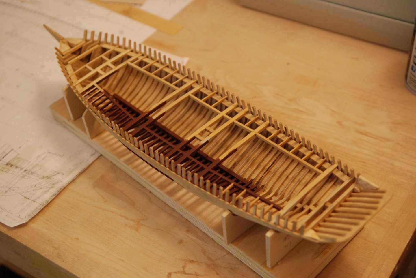
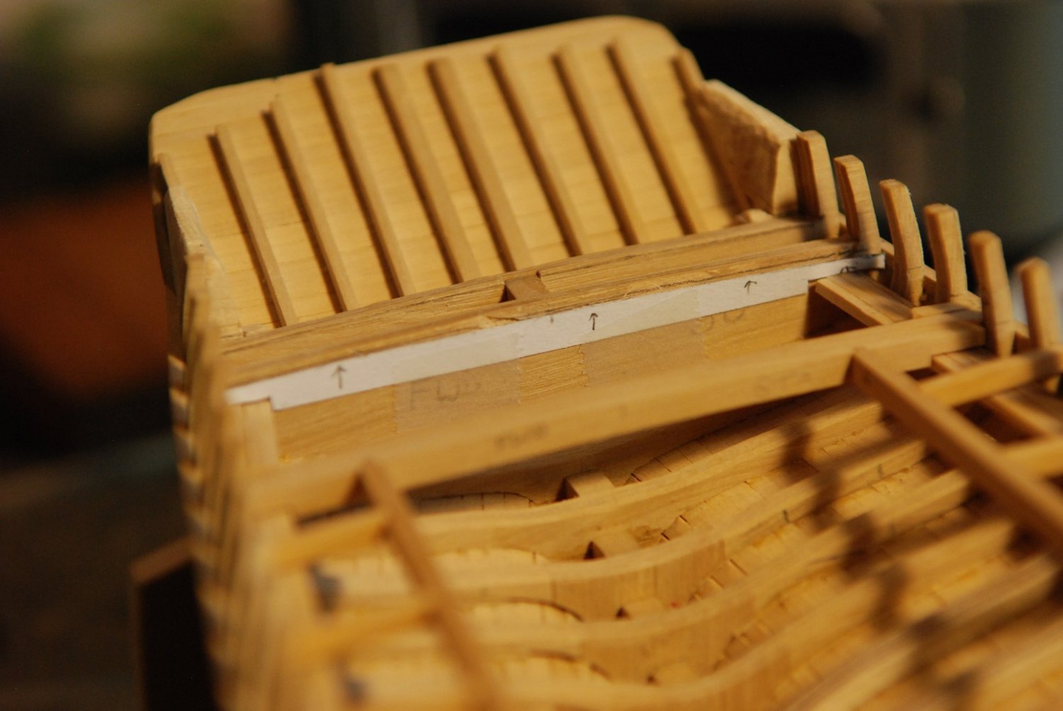
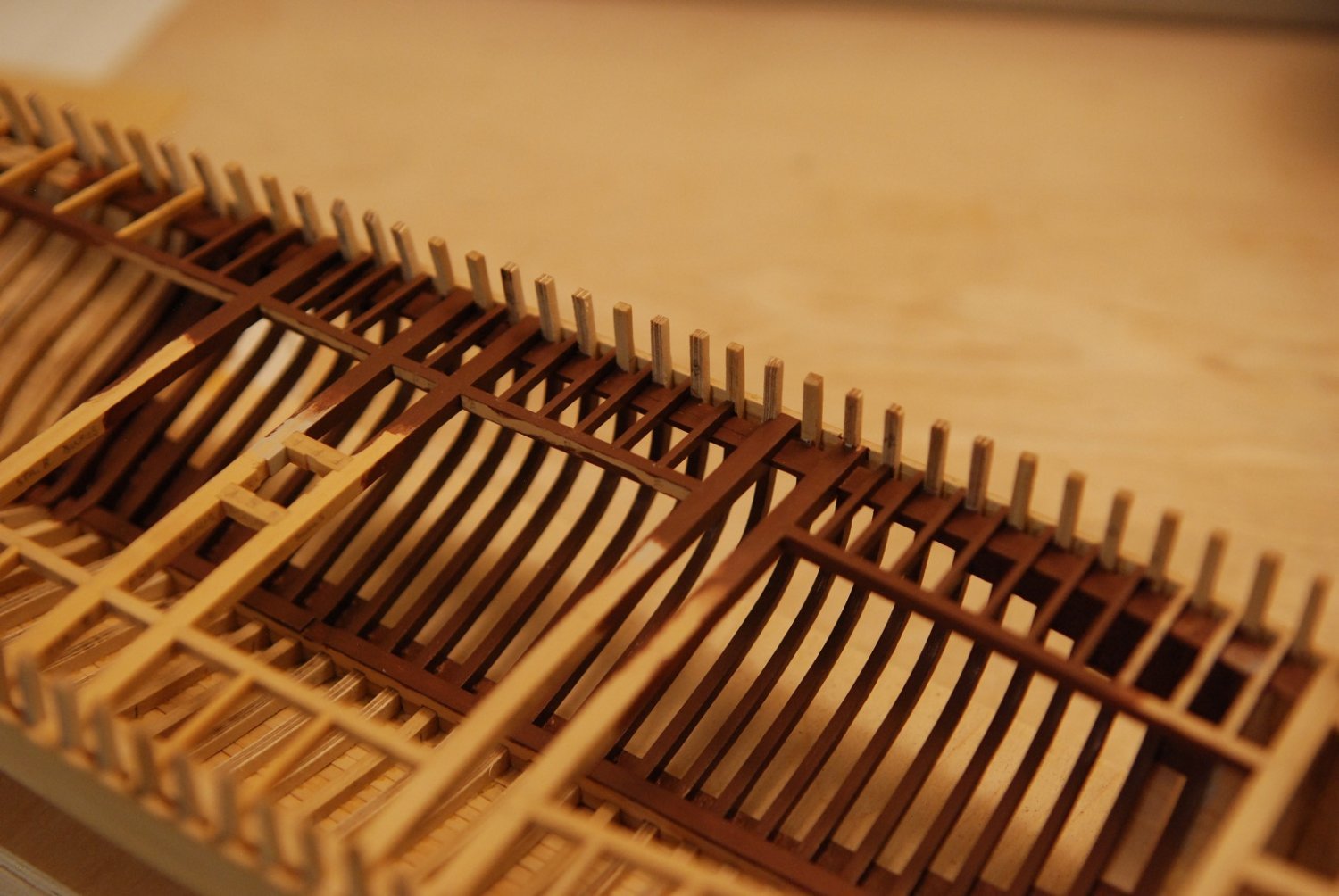
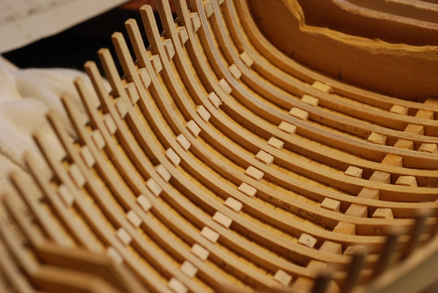
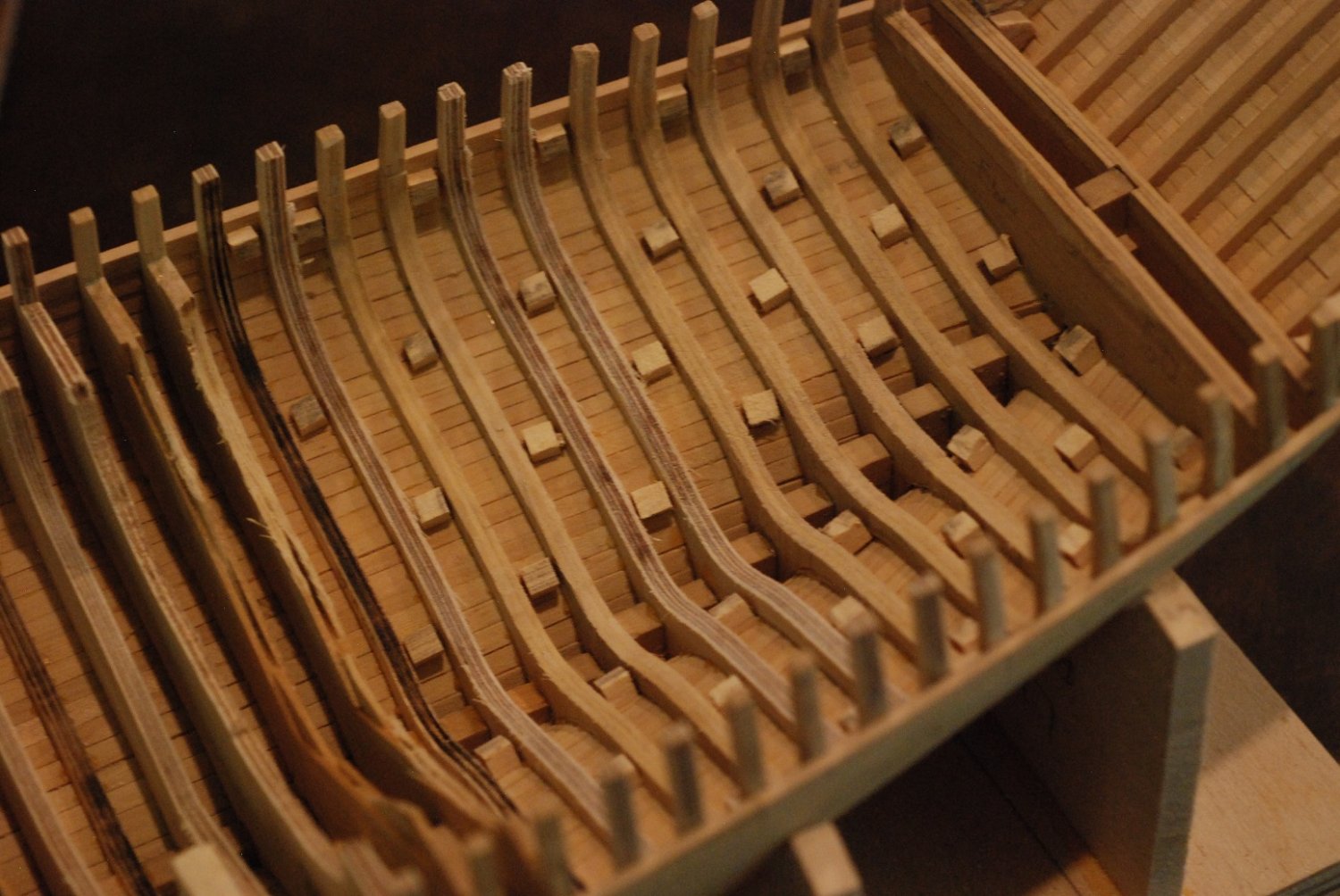
In order to stabilize the ground-out bow segment, I moved on to installation of the deck clamps. In this picture, the measuring blocks for the molded dimensions of the frames at the level of the sheerline have been removed. In their place, new blocks have been installed that properly space the deck clamps from the sheerline.

Using these blocks, the initial stringer of the deck clamps was installed. (I guess this particular piece would be called the deck clamp, and then additional pieces inboard of it would be the beam shelf.)
These spacer blocks were then removed.

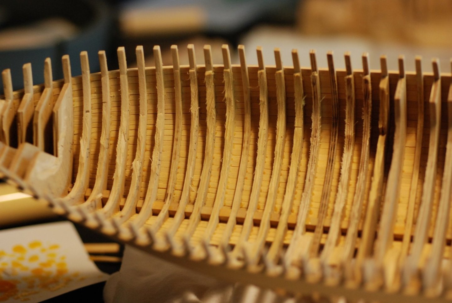
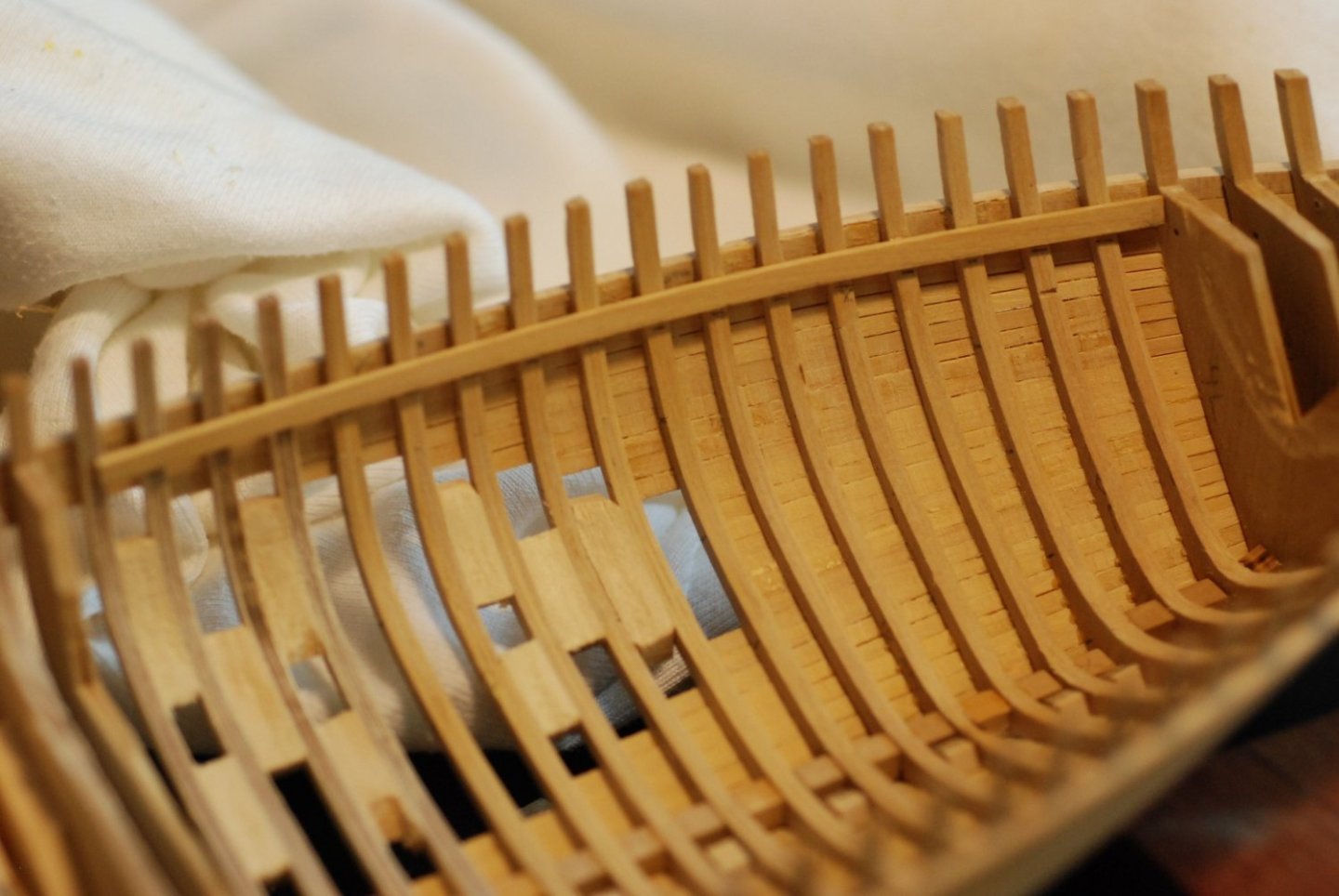
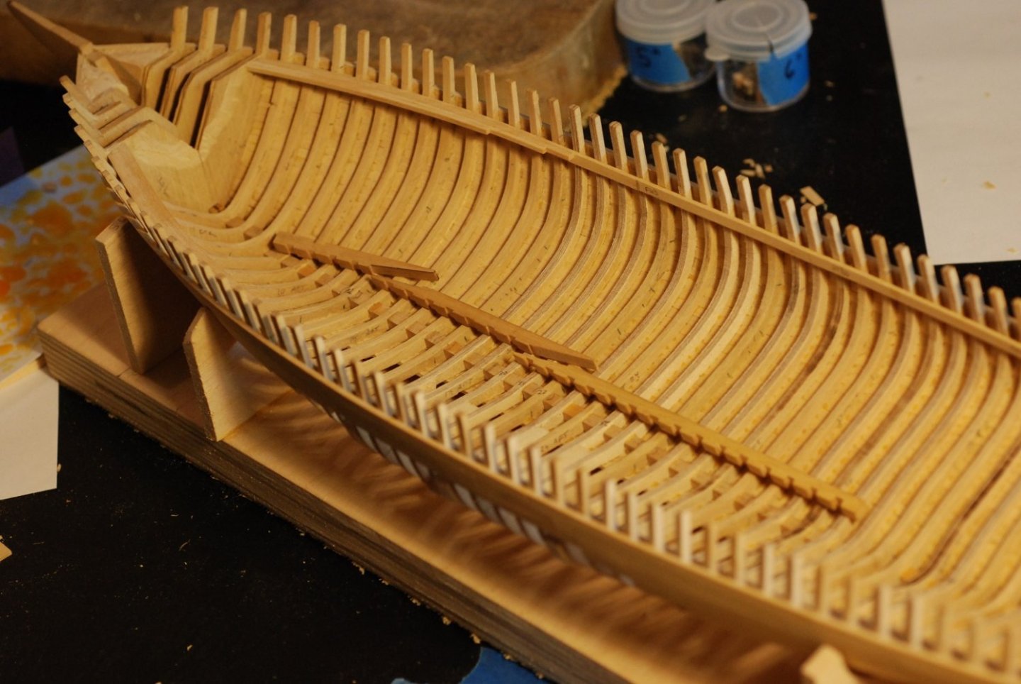
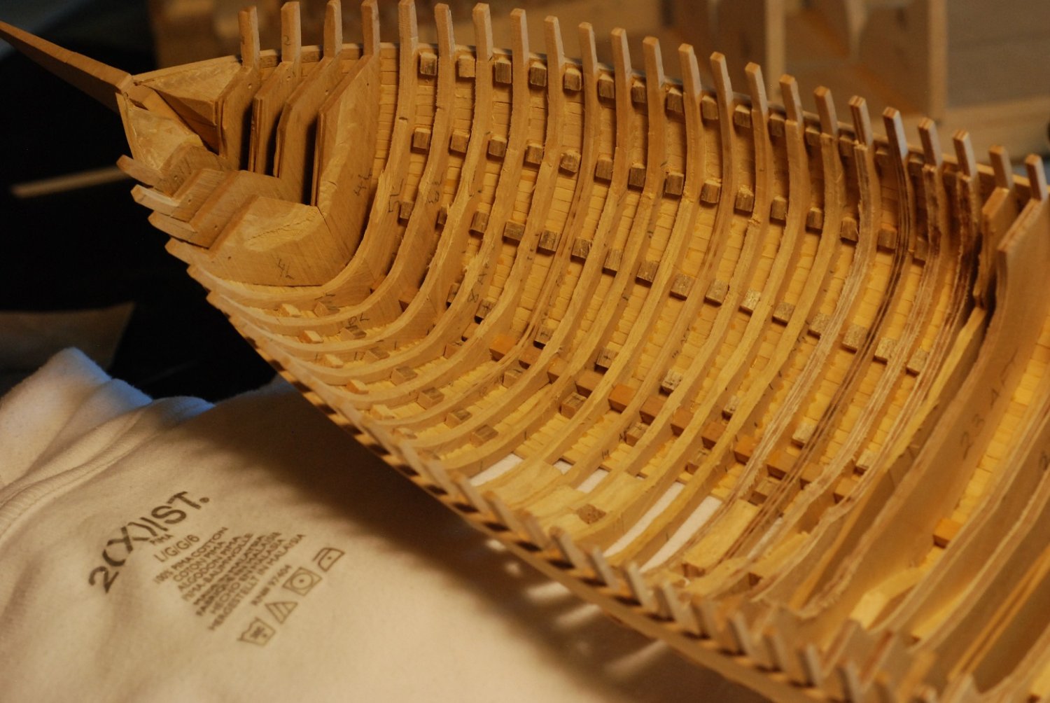
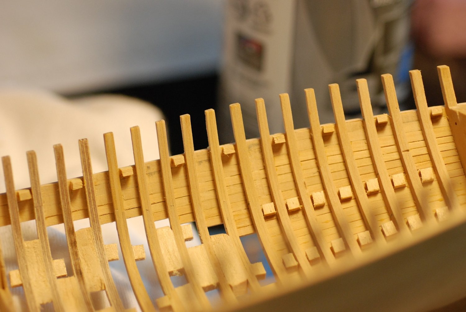
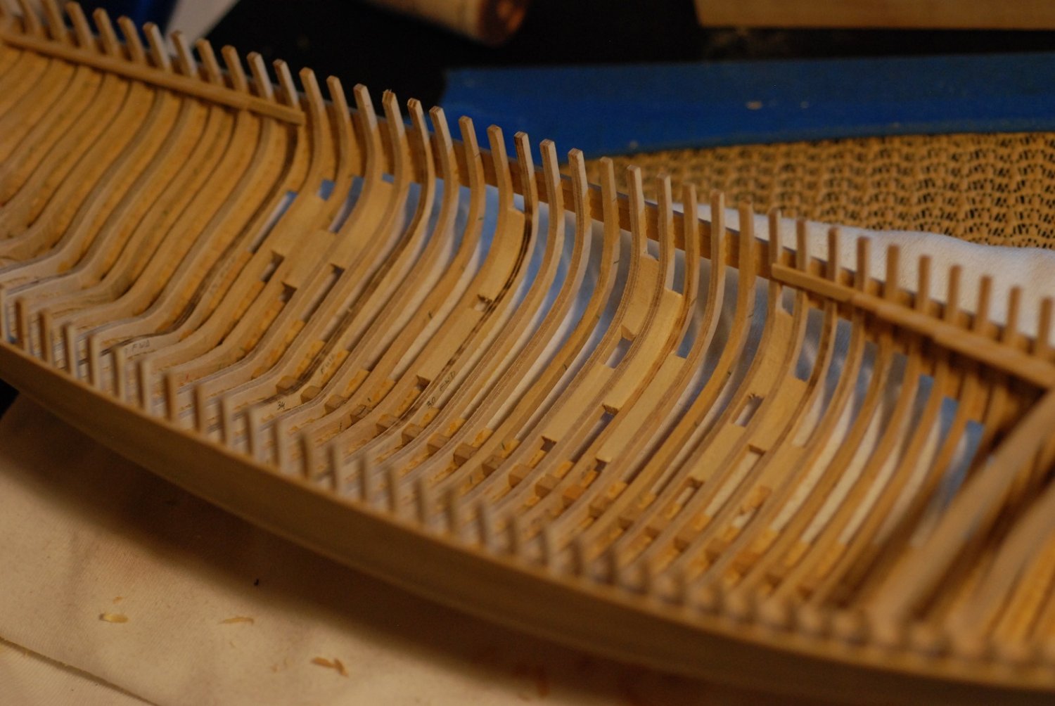
Here the thickness guide blocks are being removed from the areas where proper thickness has been achieved.

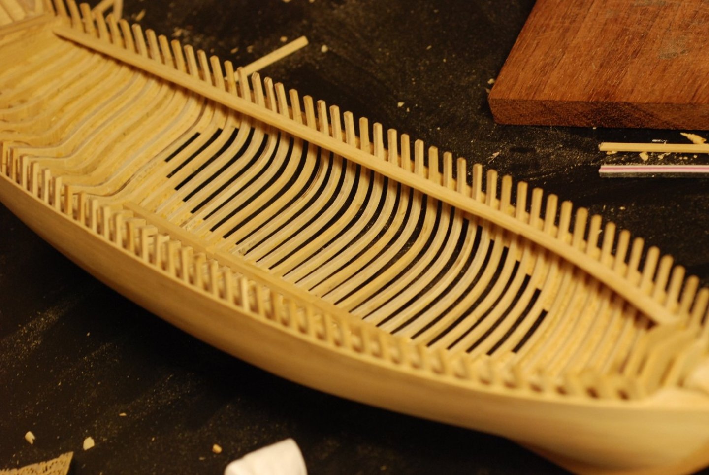
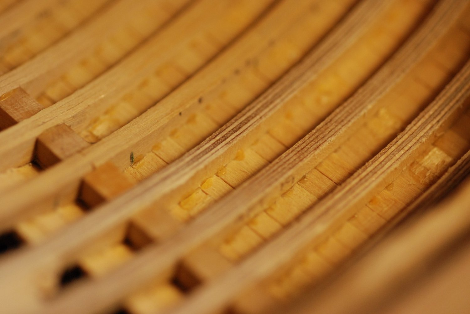
That is a very satisfying look.

If you look closer, though, you can see the difference between the frames that were made from sandwiched layers of Castello boxwood and those made with Baltic birch plywood. Also visible are beads of squeezed-out glue from planking installation.
Now I moved on to the stern third. The two aftmost bulkheads will stay in place.

Once again, the bullnose bit was used initially.

And then thickness guides were installed. I really needed a faster way to bring the frames down to proper thickness, without the violence of the bullnose bit.

I had seen this device used by other builders on their build logs, and it appeared to be ideal for getting into small areas better than any other attachment. It requires a different handpiece attachment to the Foredom (a right angle attachment) and is a bit of an investment, but the same handpiece can be used for other useful things like an angle grinder.

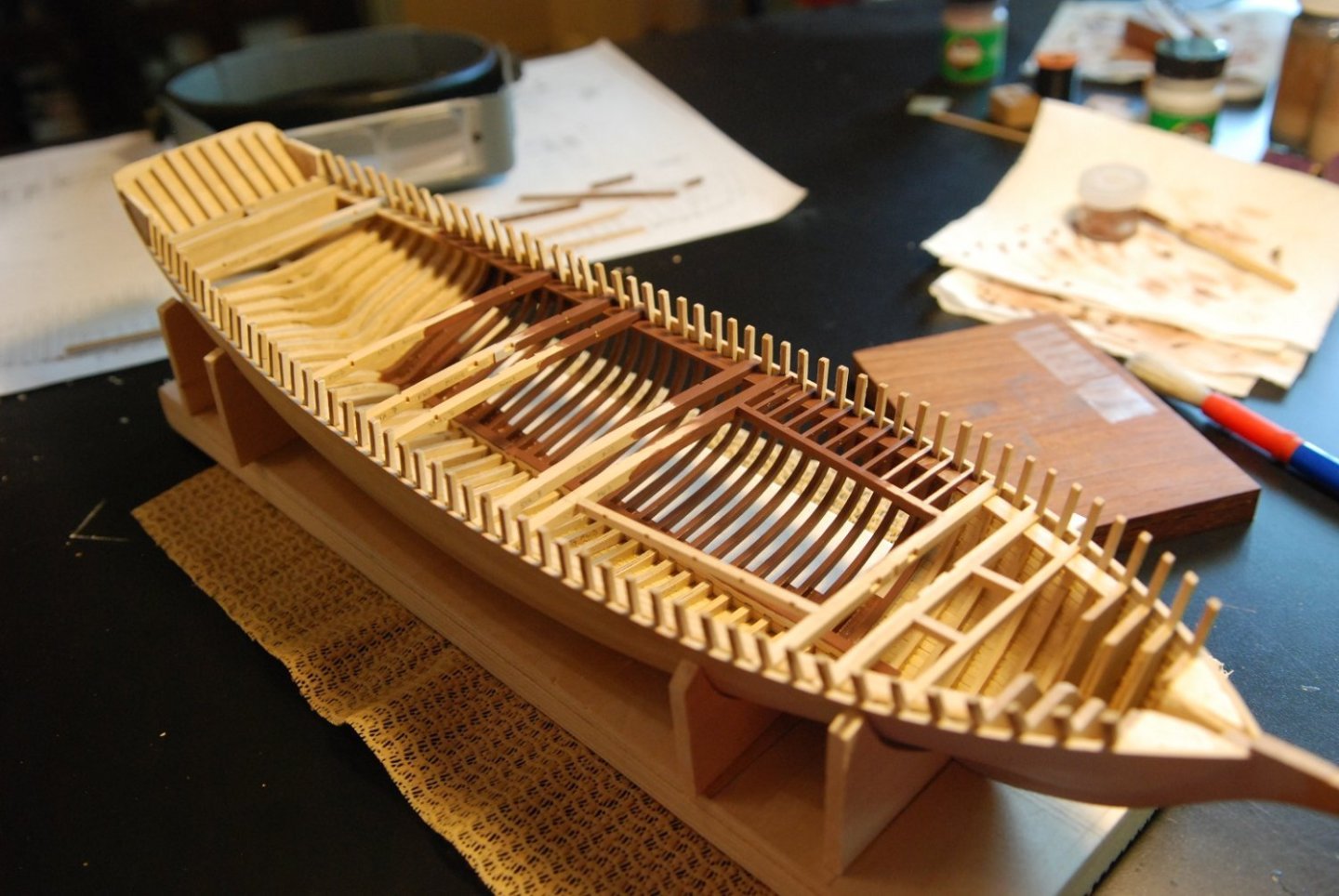
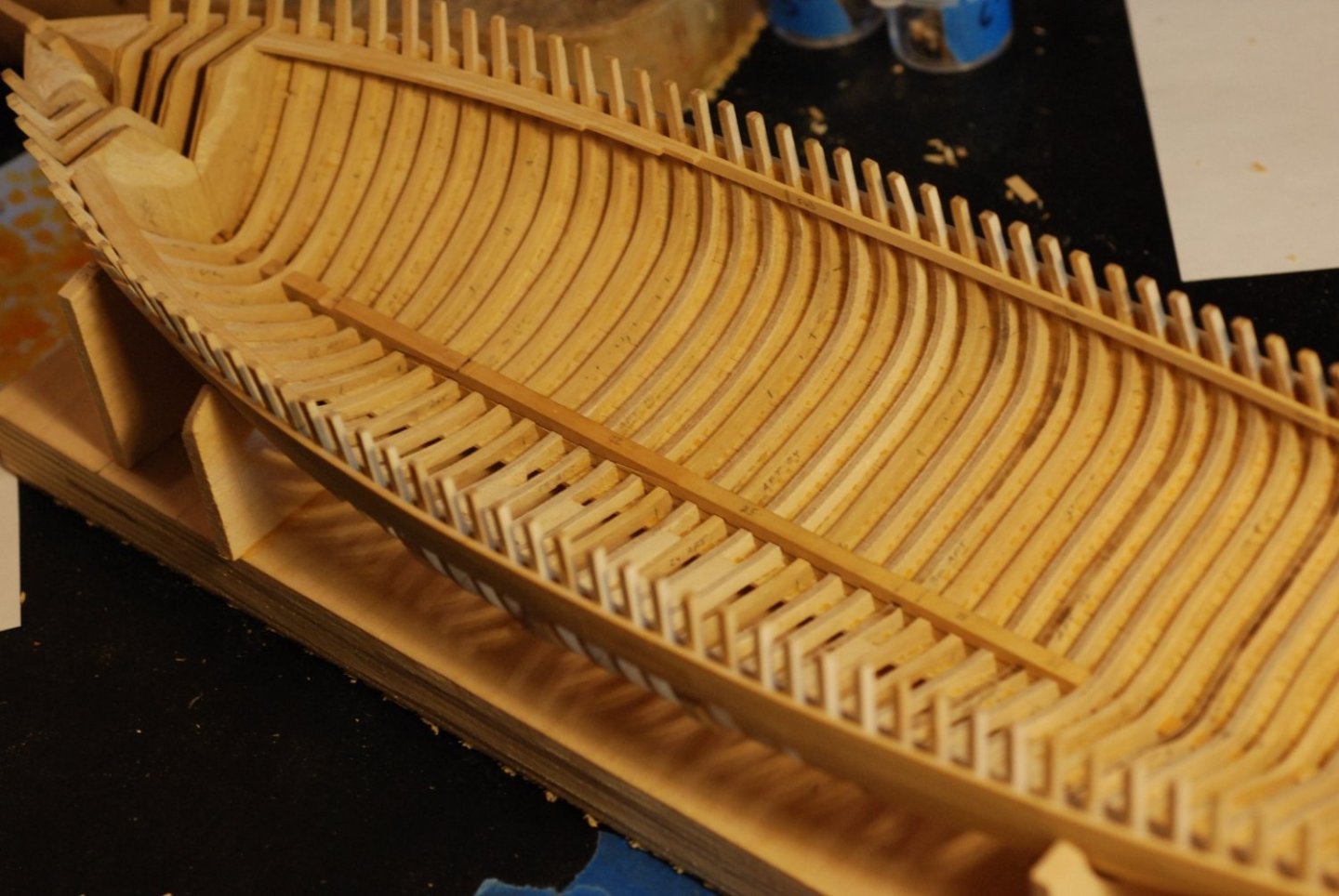
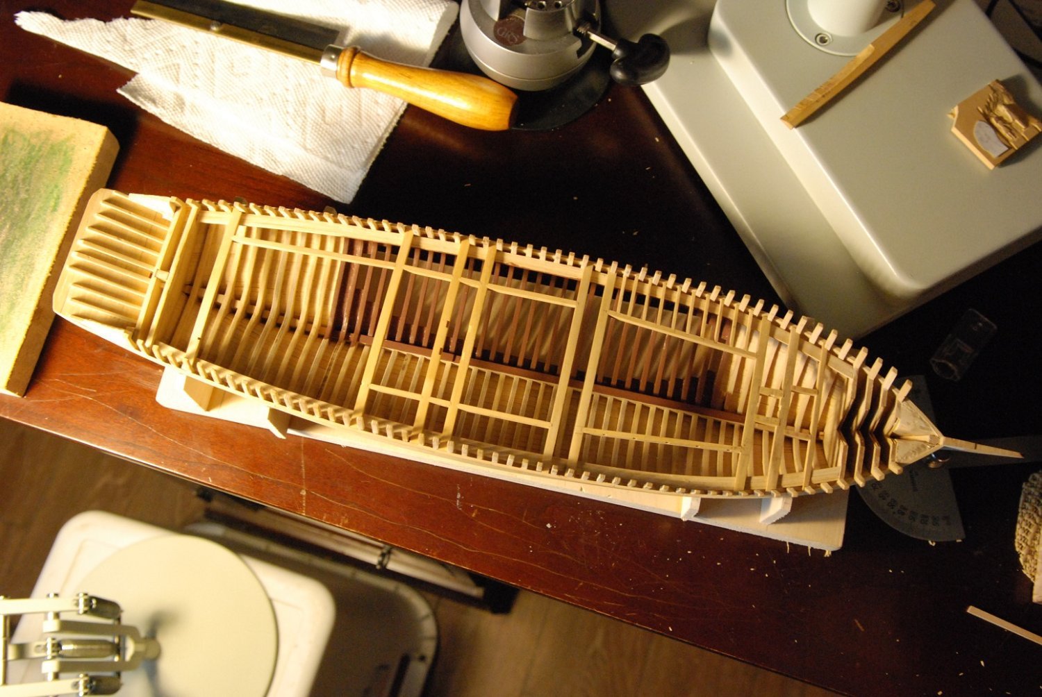
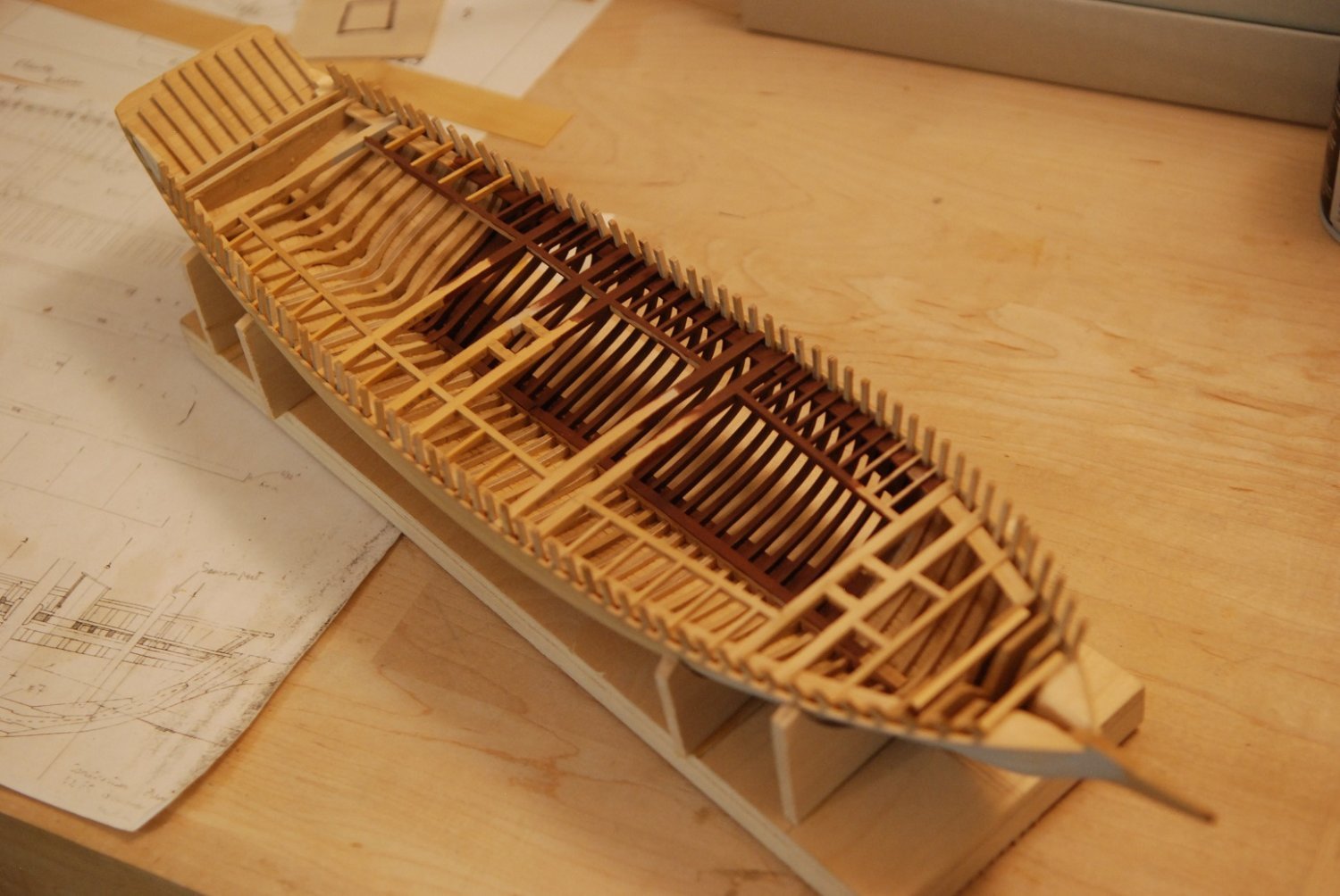
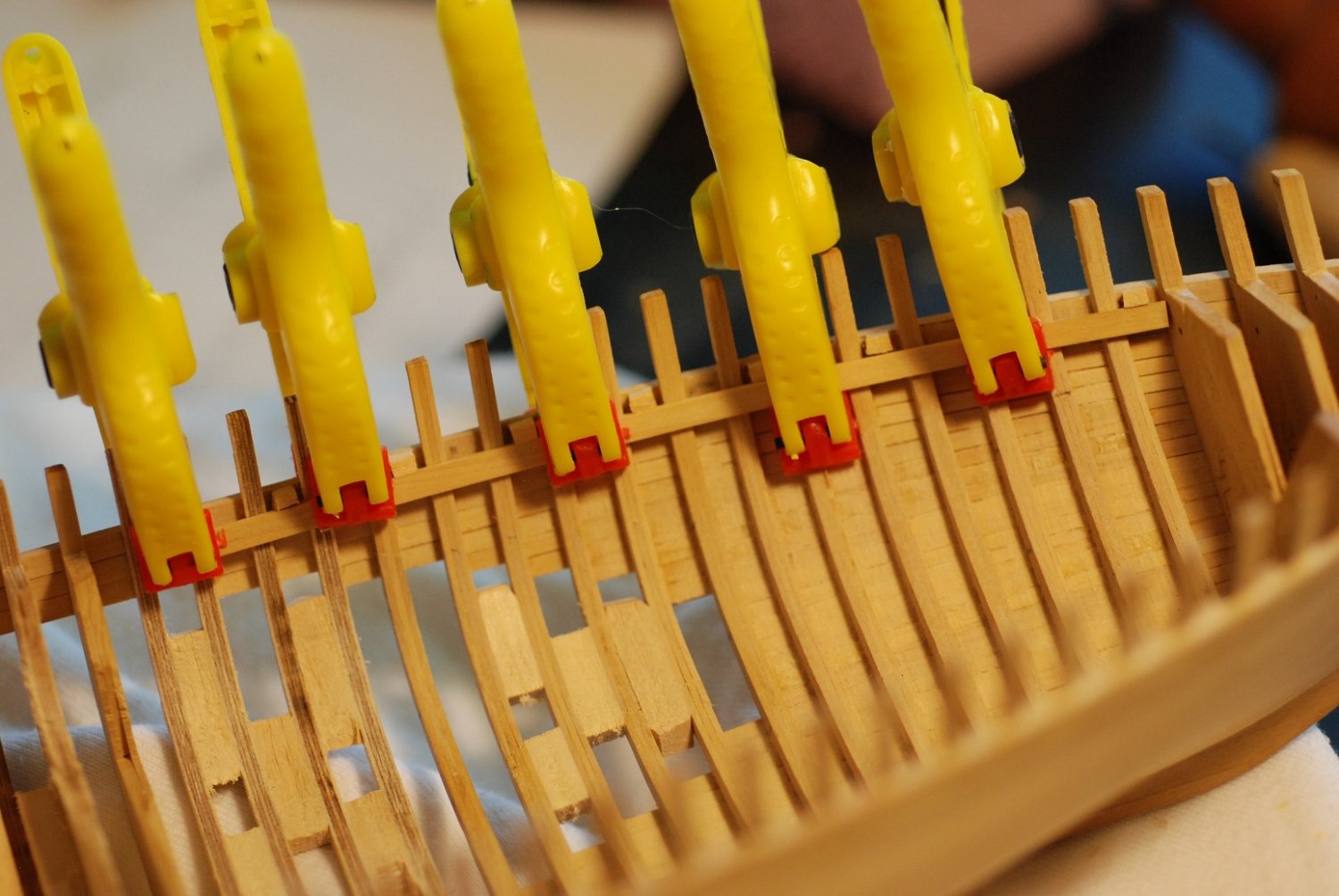
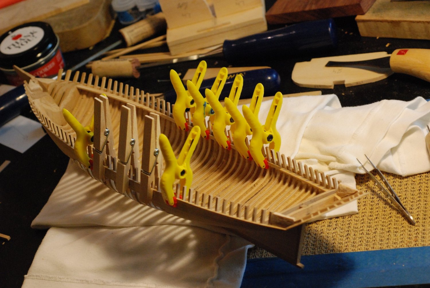
After smoothing the frames, the deck clamp was installed.
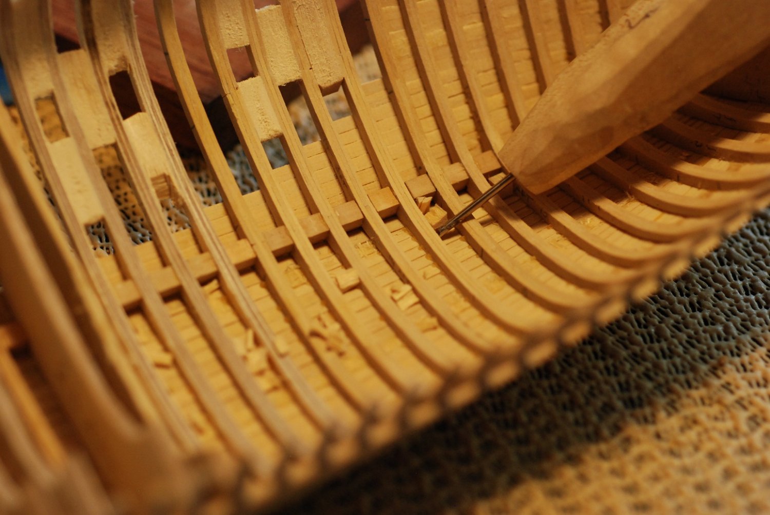
Then on to the midships portion of the hull, with the same technique. Here I am using a hand held thingie to which I could apply adhesive-backed 60 grit sandpaper for fairing of the interior surfaces of the midships frames.

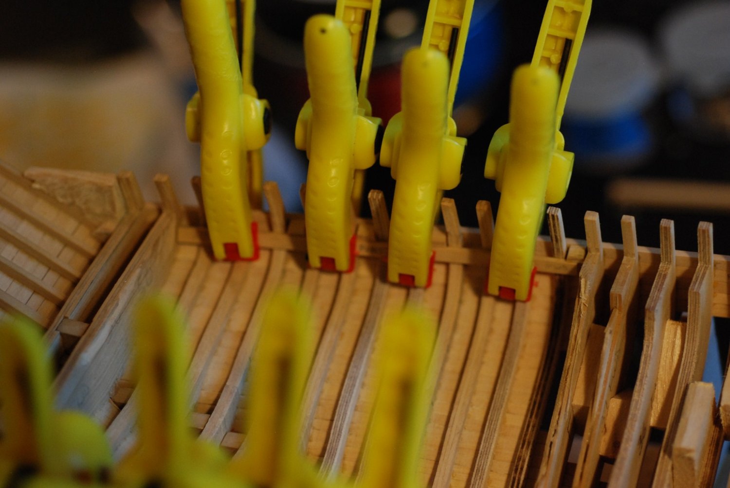
These support blocks did their job of supporting the free-floating frames in the unplanked portion of the hull.

The midships portions of the deck clamps are being installed.
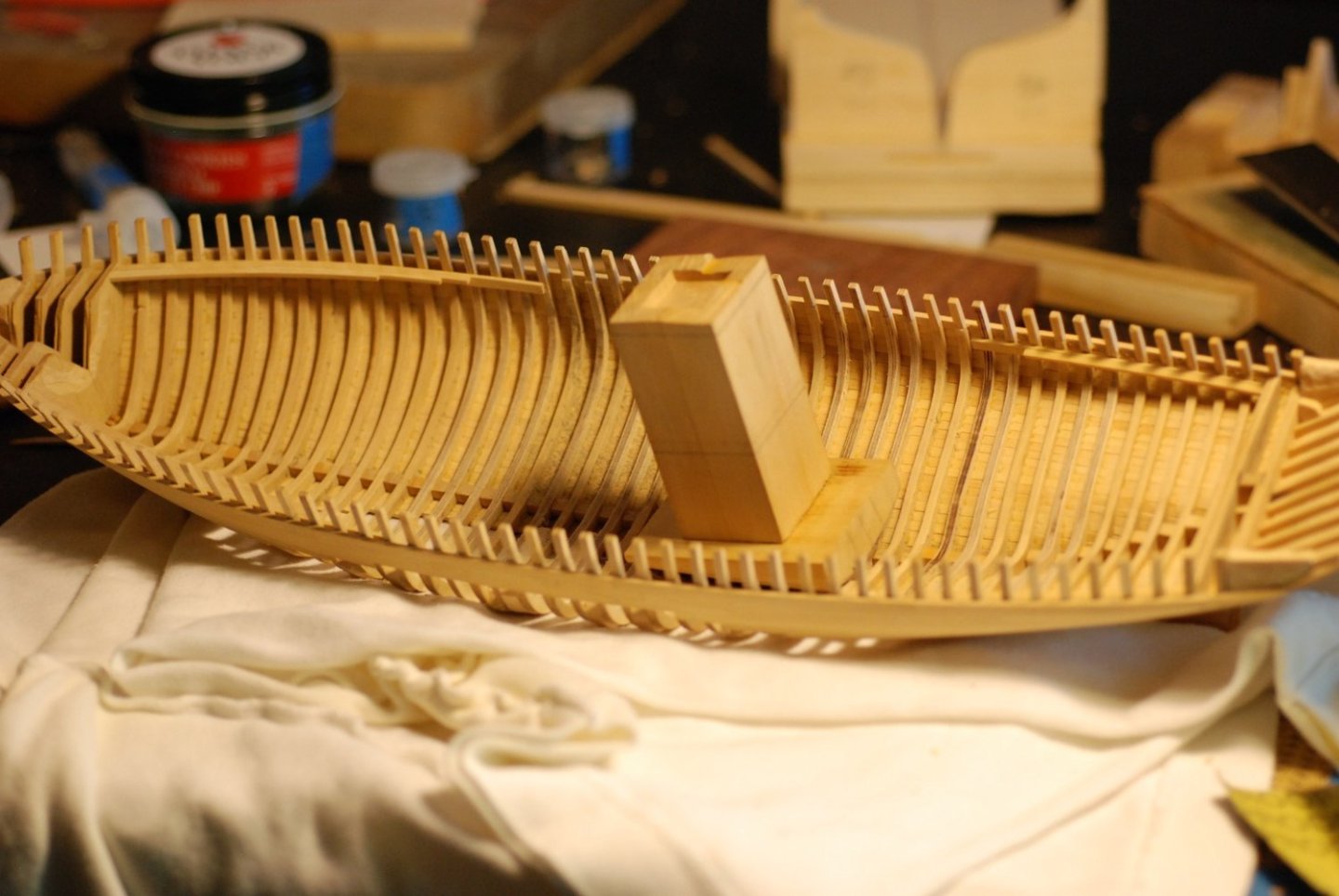
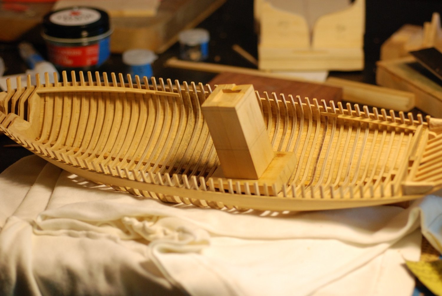
Then the keelson was manufactured in 3 parts. It was carried to just short of the deadwood.
The keelson installed.
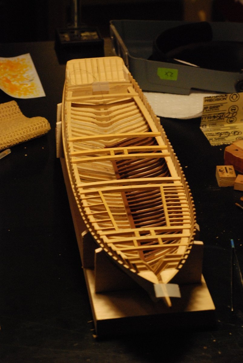
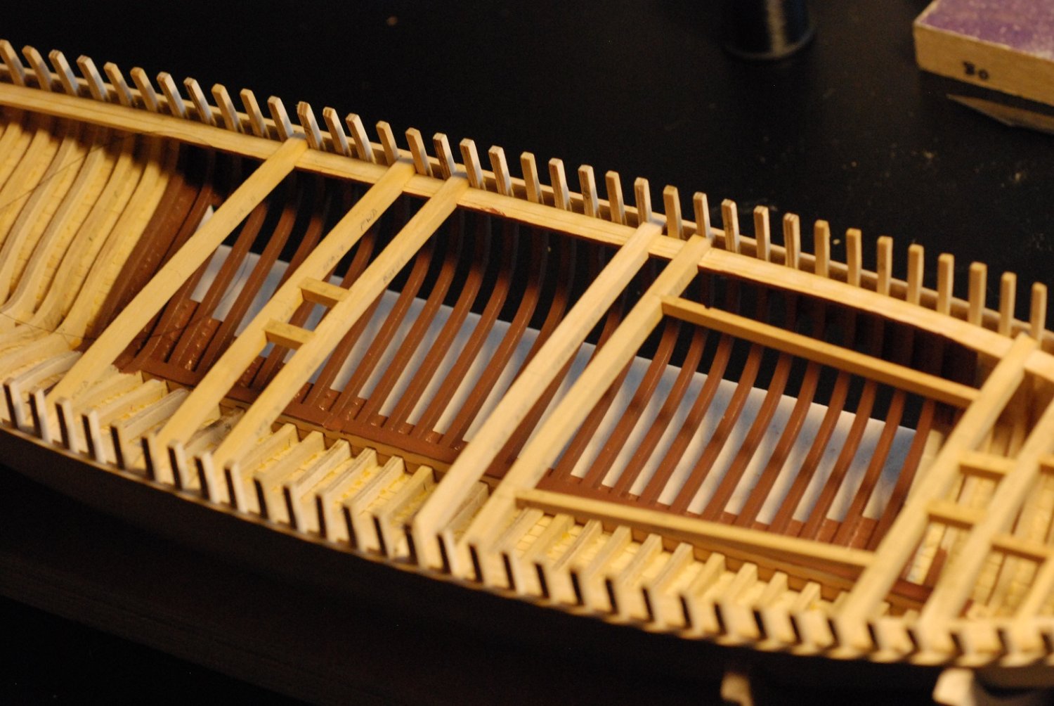
Deck clamps and beam shelves fully installed.

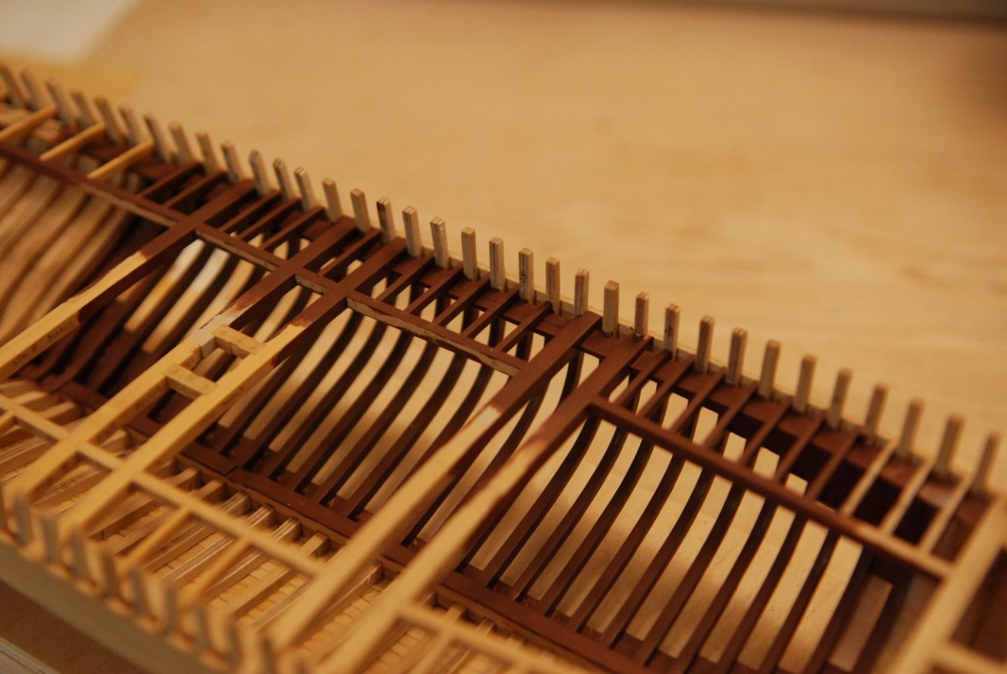
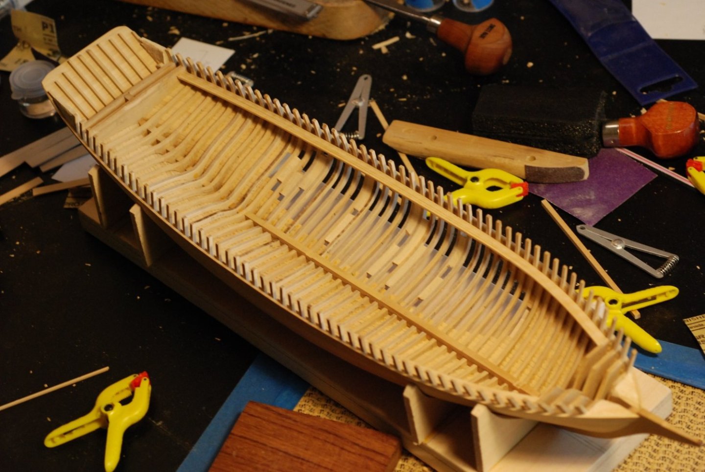
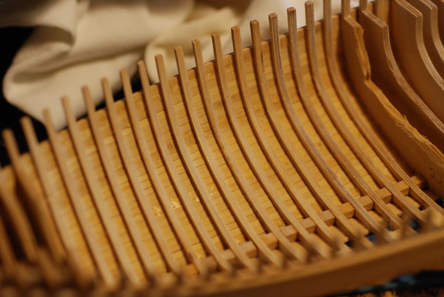
Time to remove the support pieces of wood between the frames.

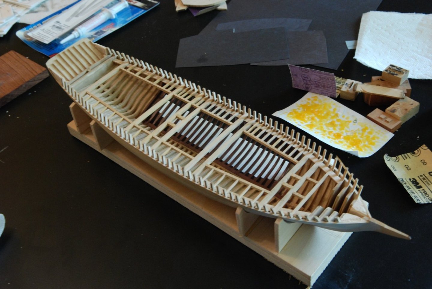
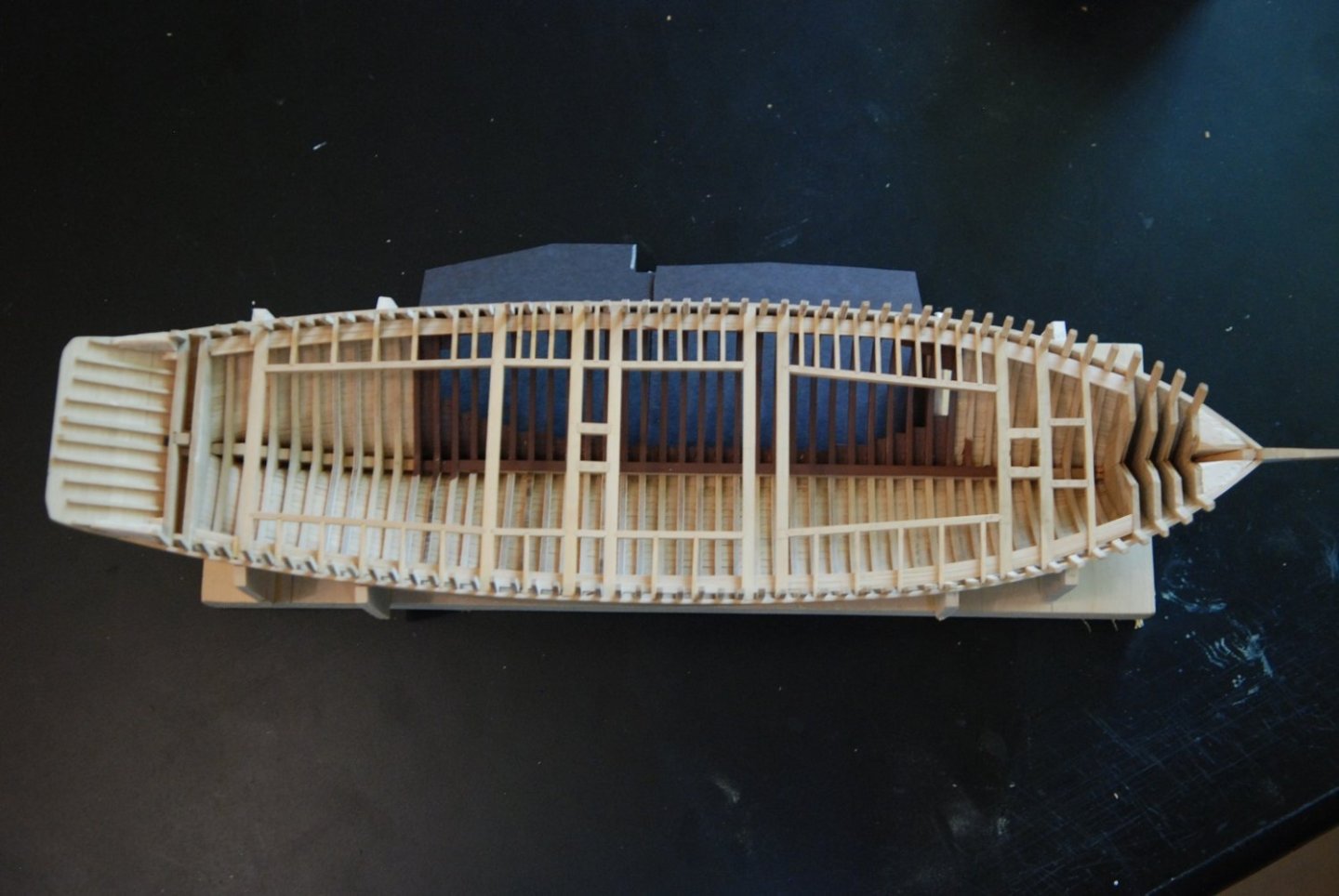
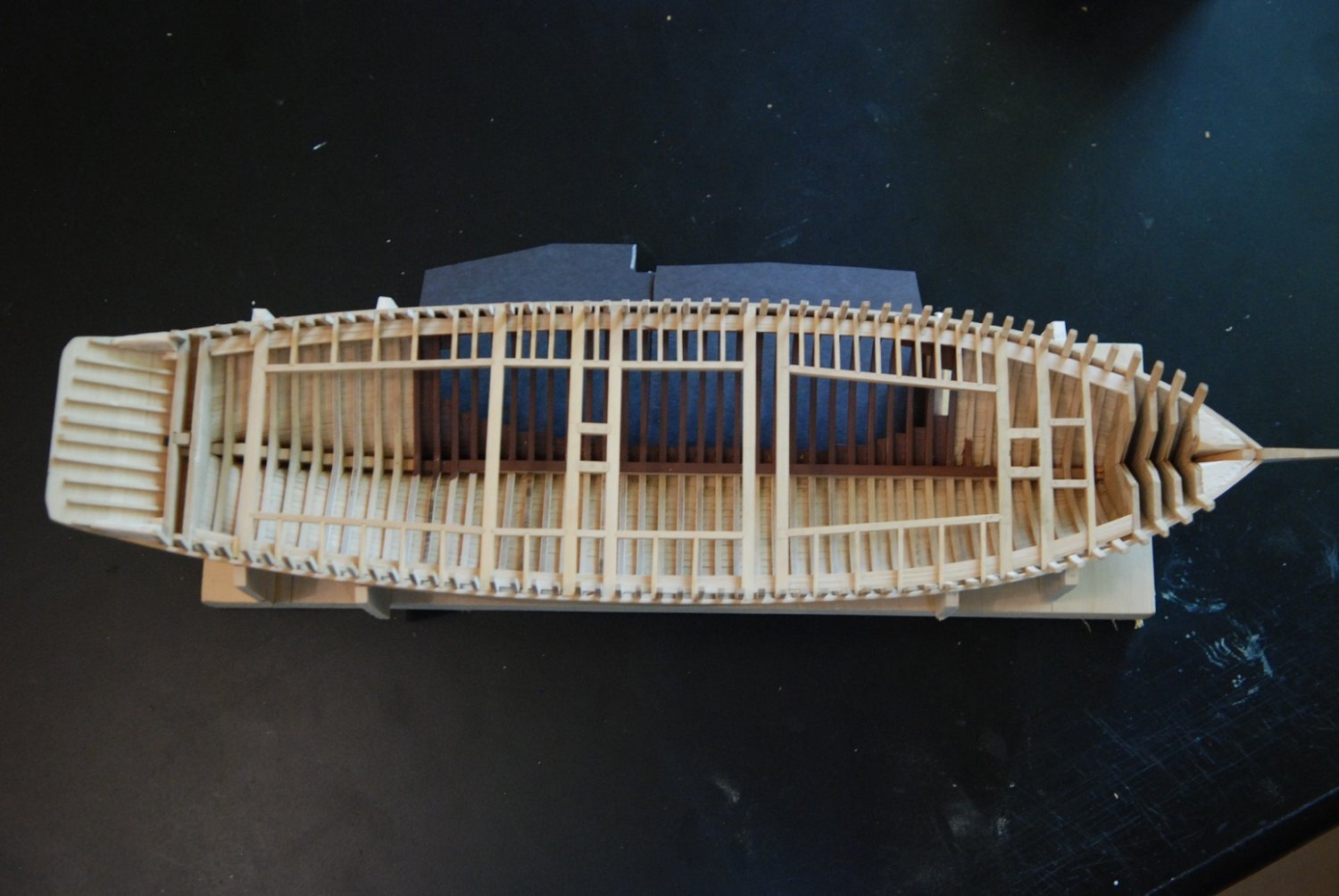
In addition to the unplanked frames, a portion of the deck in this same area will be omitted to show the deck beams, carlings, and ledges.
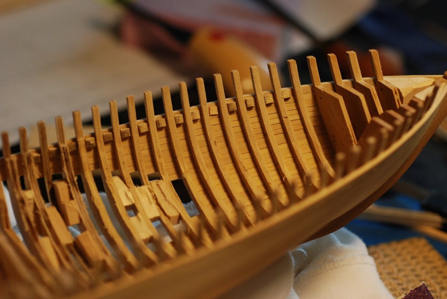
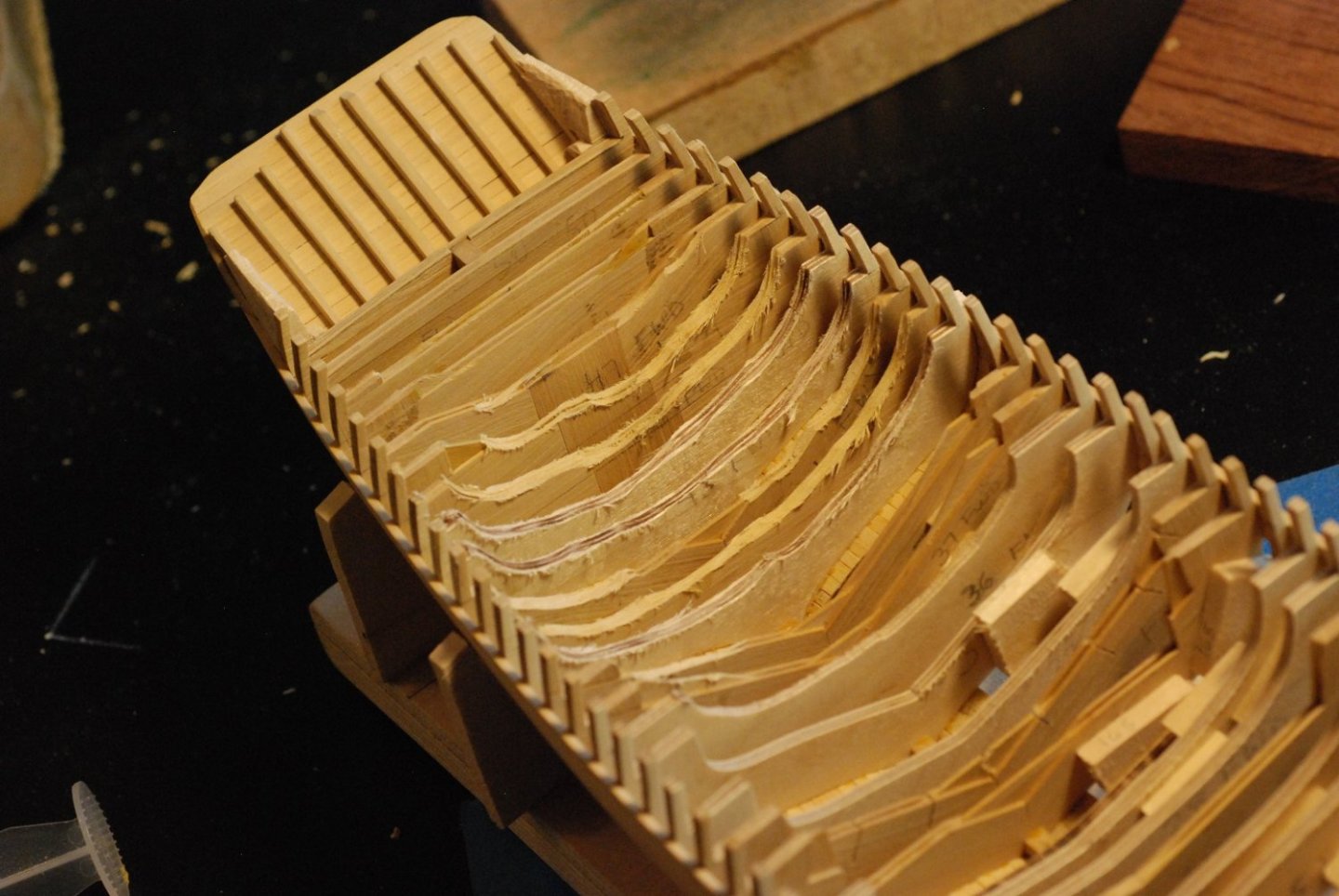
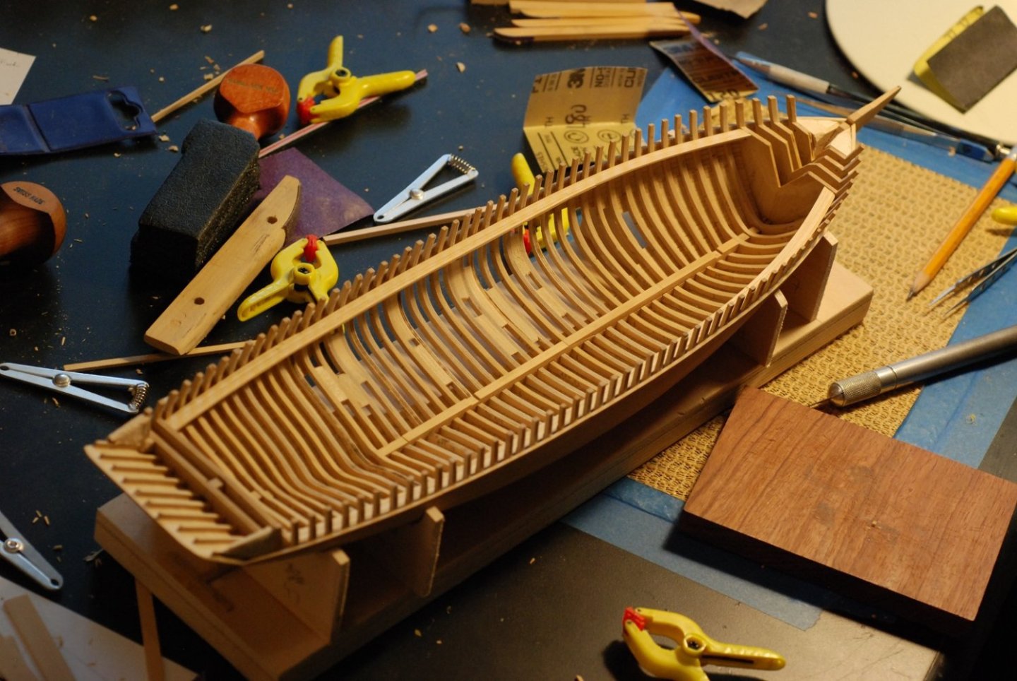
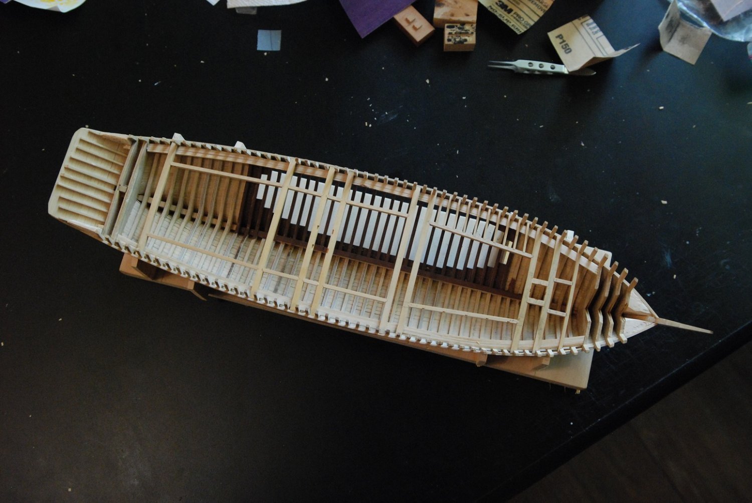
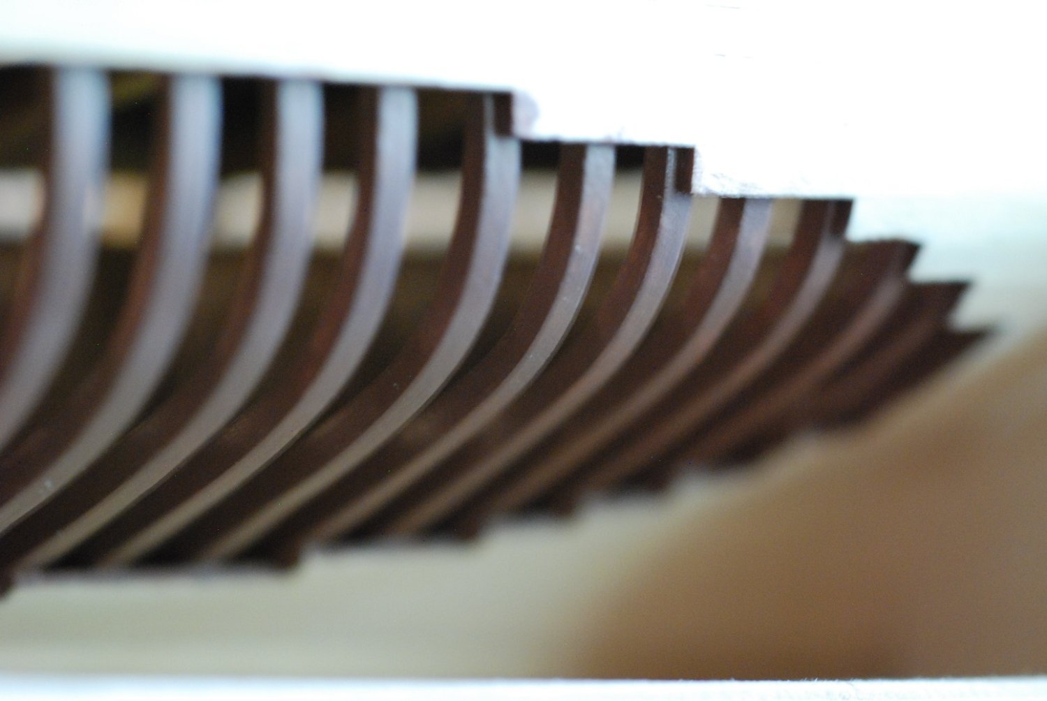
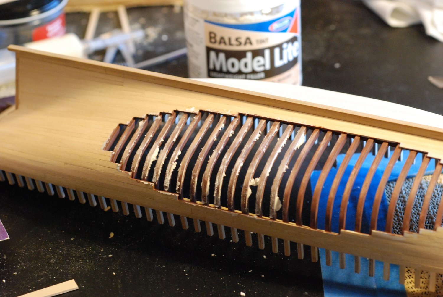
Primer has been applied to the exposed frames.

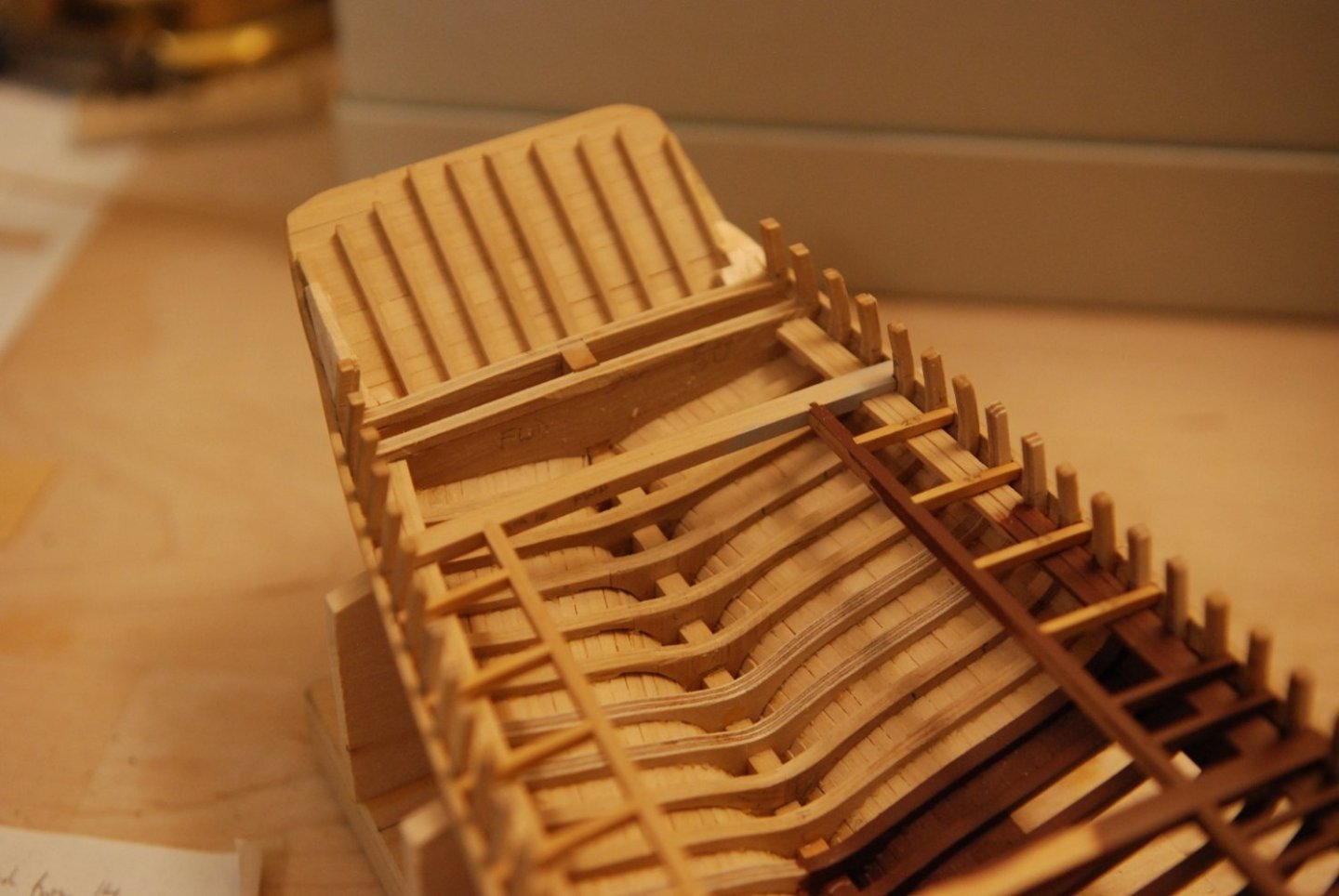
I applied some paint just to see how it would look, and the appearance indicated that smoothing with filler would be necessary. Doing this helped to make the frames look the same as one another, whether they were sandwiched boxwood or birch plywood.
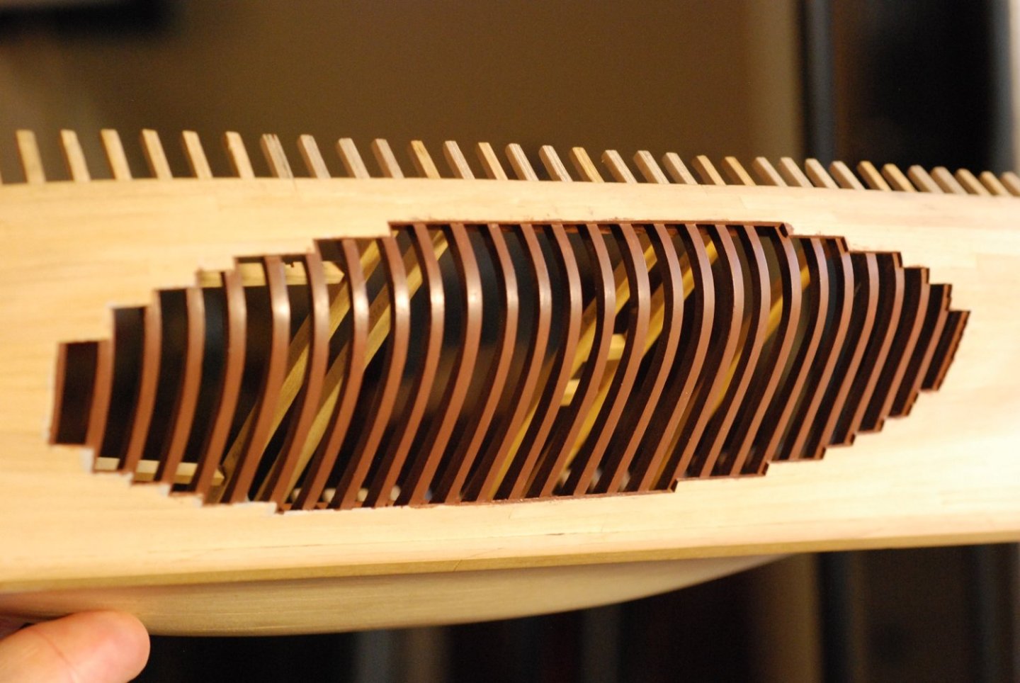
This was after 2-3 coats of brown paint.

Since the deck will be partially unplanked, I also applied the paint to the portion of the interior that would be visible through an unplanked portion of decking.
This picture gives a preview of some of the deck beams and carlings. This process will be covered in the next post.
-


.jpg.ff7f0e6fe98506a94cb46bdadbd54a86.jpg)
.jpg.366caa9e4f22ad1456f1f4990c73a3ea.jpg)
.jpg.82f5a5fa59bf63263cc2c930d4917440.jpg)
La Créole 1827 by archjofo - Scale 1/48 - French corvette
in - Build logs for subjects built 1801 - 1850
Posted
So now we have interlocking thimbles?? Come on, Johann, this just isn't fair to those of us who might try to keep up!