Snug Harbor Johnny
-
Posts
1,500 -
Joined
-
Last visited
Content Type
Profiles
Forums
Gallery
Events
Everything posted by Snug Harbor Johnny
-
 'Saw this today, and wondered if this is accurate ...
-
You're going at warp speed on this build ... at least compared to my ship, which has two speeds - dead slow and stop.
-
I could use a few more arms and hands ... like one of those Hindu Gods/Goddesses ... to hold and manipulate items. Hmmmm, 'wonder what the Admiral might think. 😉
-
I'd likely just leave it as is, and call it 'character' - after all, at a distance the thin gaps are not very noticeable ... close up pics always magnify any defect or every bit of 'fuzz' on rigging lines. Sanding and refinishing is a pain and would amount to a 'delay of game' - but there is an approach that might be less trouble, given the mahogany-like appearance of the lower part of the hull. That would be amber shellac. Cans of Zinsser 'Bull's Eye' amber shellac do just fine. Apply the shellac (and I tend to use the clearer portion floating on top of the contents of the can) with a thin artists detail brush to get into the cracks, then wipe away any excess on the adjacent planks lightly and quickly with a lint-free cloth bunched up. The shellac in the cracks will dry in a few hours and shrink as the alcohol (methanol) solvent vaporizes. The solids left behind will have partially filled the crack, and each successive application will fill the cracks more until totally filled - and the color should be pretty close to what you have now. A very light pass with a bunched cloth having a little plain denatured alcohol on it will remove any traces of shellac on the adjacent planks, but will not affect either the poly coat or the crack filling. In cabinetry work with mahogany, larger cracks are filled with 'stick shellac' melted by candle flame to liquify it before forcing the goo into the large fissure (made either by repair or perhaps a less than satisfactory joint) with a small spatula or large dental tool. It solidifies as it cools and can otherwise be blended over with regular shellac (color modified as needed). Stick shellac comes in several shades to accommodate other woods, but this technique does not apply to you model's situation.
-
'Great buy, mate.
-
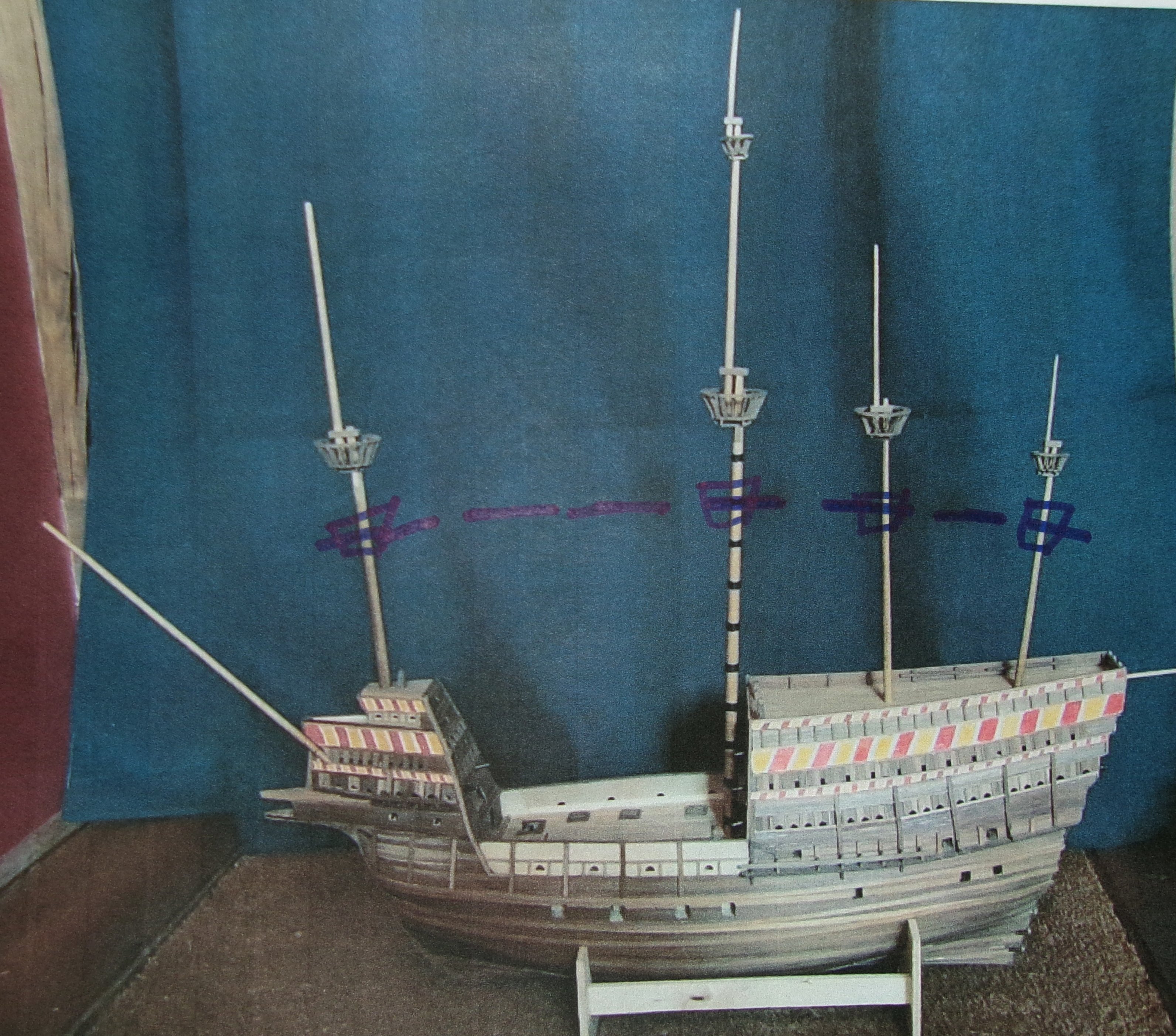
Your decorated castles are absolutely fabulous ... The fighting tops being on a 'curved trajectory are attractive, but when I get around to ever finishing a GH, I may favor a lower position for the fighting tops (topmasts look fine) as marked below. But the fore top could be just about on the level as the main top ... hard to decide - but when the time comes I could start with higher first mast segments and them trim from the bottom as desired. Given the crammed troop loading and extra armaments in the castles and tops, its no wonder that the Mary Rose capsized like the Vasa ... much to our present knowledge.

-
Be careful with the bowsprit from here out, mate. Many have had little accidents with clippers in general (and other types) where breakage occurs with the spar and other bits like dolphin striker and whiskers.
- 29 replies
-
- 1
-

-
- Cutty Sark
- Revell
- (and 1 more)
-
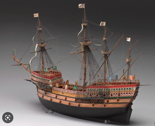
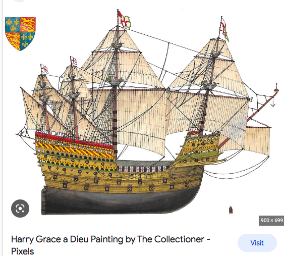
I've noticed that on the Anthony Roll, the first section of masting (as well as the bowsprit) seem 'impossibly' tall - topped by modest mast sections. This depiction is also seen in other contemporary art. Talk about instability in all but the lightest breezes. The old Sergal 1:65 Great Henry used proportions like that in the kit design, and examples of more recent art also take after 'Anthony Roll proportions'. Yet there are examples of what seem to be more likely (sea worthy) mast length proportions both in art and models as shown below:
-
G'day, mate! We're glad to welcome another member from 'down under'.
-
Bare wood model decks not in a case can get dirty over time, and fine dust can get in the grain of the wood. A thin coat of clear shellac or varnish can prevent this, and make future dusting/cleaning easier. Note that 'stain' has a tendency so soak into some of the grain more than other parts of exposed wood that can lead to uneven coloration. A way to limit this effect it to lightly apply a 'stain prep' or wood conditioner (Minwax makes a pre-stain conditioner) before applying colored stain. The prep soaks into the grain ahead of the stain - the exposed fiber end 'drinking' the prep like through a soda straw. With a few minutes rest, a light application of stain with a gathered lint-free cloth will lay some color over the prepared wood in a way that the color will be more even, with fewer, lighter dark areas.
-
Maybe an experienced European paper modeler can recommend the makers of the 'best' designed and assemble-able paper kits. This one (once a better Fokker kit is identified and obtained) can be the 'warm up' ... A crewman on a B-17 warned of a Fokker at 10 o-clock,, and a gunner replied, "You mean the Messerschmidt?" Said the crewman, "Yeah, THAT Fokker !"
-
If anything, when in doubt, start with a higher number (finer grit) paper first (like 320) and just see what it does. You can always go coarser if you need to, rather than start too coarse - that can put scratches in the wood that have to be further sanded down with finer grits to remove, and that can make the planking get too thin.
-
'Can't say enough good things about your whirlpool project, mate !
- 185 replies
-
- 6
-

-
-
- Flying Dutchman
- Black pearl
- (and 2 more)
-
You can use a small sanding block with a fine grit sandpaper wrapped around the block - say, 220 grit. Lightly go over the area, and the block will insure only the 'high spots' are lessened. Looking at your picture, it shouldn't take much - a few passes may do.
-
Rob Riedderich used the 1:96 C.S. hull as a 'base' to make other clippers, with impressive results. Most know that Revell's 1:96 Thermopylae has the C.S. hull - and even though they nixed the second deck house, made a modified Thermie rear cabin and fudged the deadeye/shroud arrangement to be more like the Big T, that kit leaves a LOT to be desired. I've studied my stashed Thermie kit and pondered how to re-engineer the plastic Revell hull and deck to be 'closer' yet to the original, and the problems are manifold - too much to do to be practical. Often overlooked and yet essential, the subtle 'racing yacht' lines of the original T's hull are different than those of C.S. (the differences are thought to have given Thermopylae an advantage in light to moderate winds), and no wood kit ever got the T's lines right either. The correct lines are available on the internet, and can be scaled as desired. So I've studied and made drawings of those, with an eye to doing an 'old school' solid hull. We'll see if anythoing can come of that.
-
Greetings, Mate ! Check out builds over ships you're interested in ... lots of tips to find there. Snug
-
HMS Endurance 1/70 Scale by OCCRE
Snug Harbor Johnny replied to SaltyScot's topic in Wood ship model kits
Hornet's comments may apply to many of the moderately priced kits Occre sells, e.g: belaying pins that seem "fat" and out of scale (also too short for the scale they're in - presumably to avoid them breaking); 'average' rigging line supplied - which is par for the course in a majority of kits from many sources; not enough sizes of deadeyes (also they are white, so one must stain them dark) - also not uncommon in other kits; Hull lines vary in places from the known lines (not uncommon in many kits, but not hard to correct if desired); wrong size portholes for cabins (actually they are brass grommets - passible for the deck house, but the long stern cabin had no surface mounted portholes on the sides, just holes in the planking because the portholes were recessed) ... I could go on, but sacrifices were made to keep the price around $200 (varies depending on source). If the Endurance is is what someone WANTS to build out of interest in it, then the choice is between the only kit offered as a good base (as Grandpa Phil noted) to do with whatever level of accuracy desired (and some upgrade items will be purchased) ... OR they can do it from scratch for themself, with old kits (intact or partly built) as a source of some materials. If someone is looking for greater accuracy of some other ship all 'in the box' (regardless of which ship it happens to be, the object being to start a project without having to change much of anything), then a thorough researching of MSW kit reviews and builds is recommended before making any decision. But 'better' kits ... and a lot elsewhere has been asked and pondered elsewhere in our forum as to "what's the best kit"... will likely cost more to buy, and may still need a few 'upgrades' to get closer to 'authentic' - realizing that most ships went through configuration changes during their life. One should decide WHICH 'version' of a particular ship one is to build, based on what it was doing at a particular time (thus how it was configured THEN). E.g: There is the Polaris before it was converted and renamed Endurance, the Endurance as modified when it left England for South America (uncovered steering mechanism and no dog kennels yet), the Endurance when it left South America for Antartica, and the Endurance stuck on the ice where it was further modified for the Winter. The 'look' will be somewhat different for each version. -
HMS Endurance 1/70 Scale by OCCRE
Snug Harbor Johnny replied to SaltyScot's topic in Wood ship model kits
The first Endurance build log on MSW I followed was by Hake Zou, and he built it pretty much 'out of the box' and made a good looking model. Other builders have added their own logs with a few (or a lot) of modifications. You can have a look at them as well and pick and choose among any alterations that have been made ... or not. I did a kit review and found Occre's Endurance a good value. The builder doesn't have to deal with guns, gun ports, large numbers of yards, complex rigging or copper plating the underside. If you only substituted 'scale rope' (not costly) for the rigging, and perhaps looked at Hake's rigging suggestions, you'd likely appreciate the results. Fair Sailing ! Snug -
Eastern Europe has a long history of sophisticated paper modeling of all sorts of things. Of course paper is thin enough to be viewed as a two-dimensional material, and paper model design flows from how one can bend, twist, roll and otherwise join 2 dimensional components. I wonder if this background (school of thought or shared history?) is reflected in more recent kits coming from Eastern Europe. Model kits (non-ship) from U-Gears are laser cut on thicker wood stock, thus have a third dimension. But the U-Gears offerings are built like puzzles without having to bend pieces (for the most part). The Nitkin ship kits have a mixture of thick and thin wood parts, and the the planking does require bending. The pre-cut shapes of all the planks likely correspond to a certain "perfect" hull shape (determined in the design phase). The hull frames do have lines on each side to serve as a guide for how to fair them ... but get the builder only 'so close' to the theoretical ideal. Fairing is a tricky (artistic, actually) process where not trimming/sanding quite enough versus going too far can be measured in thousands of an inch (or hundredths of a millimeter). Perfectly 'faired' hulls (whether frames or bulkheads, with filler wood or not) won't have any 'kinks' or 'dips' in planking (or springy wire used to lay over a hull in progress to judge the fairing process) put over the exterior. A plank length designed to fit perfectly over an ideal faired distance will appear short or long in its place depending if the fairing along the hull covered by that plank is not exact. There's the rub! 2-D laser cutting cannot pre-fair ship frames, and frame assembly also produces slight positional variations in the framing that even 'assembly jigs' (on smaller models) can't completely prevent. With regular plank-on-bulkhead kits, one must cut, shape and fit one's own planks from long pieces of planking stock to conform to whatever fairing shape the modeler happens to have achieved on the hull. This may seem inconvenient to some, but the result will be appropriate for the hull being built. The concept of a 'fully engineered' kit where all the shapes have been pre-determined and will 'fit like a glove' is alluring indeed - but I fear that it will likely remain something of a "Holy Grail". We're forced to deal with at least a few assembly variables that still require a modeler to 'work around' a few surprises. But isn't that what model ship building is all about? So I wouldn't be too hard on Pavel because of the very high (and difficult) bar he's aiming for, and consider the 'partnership' of sorts that exist between kit designer and model builder. Consider the words of old Einar Billing, founder of Billing Boats: "The most important point is that this kit is intended to be built, and not merely assembled. In consequence, you must not expect the parts to fit together perfectly - it will be necessary to exercise skill and imagination in the building of this kit. I have tried to make the parts as accurate, and the instructions as precise as possible - but thought and care should be exercised during the construction. After all, any child can put a puzzle together. I wish you a lot of success in building your model."
- 58 replies
-
- 5
-
-
-
- Santa Maria
- Ships of Pavel Nikitin
- (and 1 more)
-
The amount of darkening varies from where in the tree a sample comes from - heartwood (older and deeper in the tree trunk) verses 'sapwood' (more recent wood laid down towards the outside of a log as the tree grows). There is likely a variation in chemistry. Also, different trees of the same species can vary in color, possibly due to genetic variation as well as differences in the soli components/nutrition on the spot where each tree stands. I've had mahogany darken long after being completely sealed in a a French Polished shellac, so I can't see how oxygen could get through the coating. (Oxidation does change unprotected wood more rapidly.) So perhaps the presence of light as well as a delayed chemical reaction may be the mechanism of action. Yet the change is on or near the surface, so re-cut or freshly sanded wood is light in color.
-
Hello from the Chesapeake Bay area
Snug Harbor Johnny replied to SaltyScot's topic in New member Introductions
Old timers from Maryland may remember National Beer ... From the land of Pleasant Living - Brewed on the shores of the Chesapeake Bay. -
Hello from the Chesapeake Bay area
Snug Harbor Johnny replied to SaltyScot's topic in New member Introductions
Ahoy, mate ! this early bird is glad to welcome you to MSW. I found that going through many builds of ships I found interesting provided a world of information - as well as tips and work-arounds to the occasional glitch that many model designs have. Of course, there are modelers in plastic, metal and paper here as well, but working in wood has many advantages - especially when it comes to redoing something. My #1 suggestion when building is to use 'scale rope' (bought or self-made) instead of the often 'fuzzy' thread one can find in a wood model ship kit. #2 might be to use better blocks/deadeyes. -
Q. Why wouldn't the planking cooperate with the model maker? A. They were on strake.
-
Don't forget the painting of Henry setting out for Calais - it shows shields all around the top decks - presumably supported by open railings - so archers could shoot through the gaps between shields and still have a lot of protection via the shields. Also, boarding netting would only be put up when the ship was readied for action with an enemy. Henry was on a diplomatic mission, so there are no nets in place.
-
Welcome aboard , mate! Your ship look great, so if you do the rigging - try and use scale rope from Ropes of Scale or Syren ... or even make your own. Compare MSW builds with them and you'llsee the difference in the close-ups.