Snug Harbor Johnny
-
Posts
1,508 -
Joined
-
Last visited
Content Type
Profiles
Forums
Gallery
Events
Everything posted by Snug Harbor Johnny
-
 Eastern Europe has a long history of sophisticated paper modeling of all sorts of things. Of course paper is thin enough to be viewed as a two-dimensional material, and paper model design flows from how one can bend, twist, roll and otherwise join 2 dimensional components. I wonder if this background (school of thought or shared history?) is reflected in more recent kits coming from Eastern Europe. Model kits (non-ship) from U-Gears are laser cut on thicker wood stock, thus have a third dimension. But the U-Gears offerings are built like puzzles without having to bend pieces (for the most part). The Nitkin ship kits have a mixture of thick and thin wood parts, and the the planking does require bending. The pre-cut shapes of all the planks likely correspond to a certain "perfect" hull shape (determined in the design phase). The hull frames do have lines on each side to serve as a guide for how to fair them ... but get the builder only 'so close' to the theoretical ideal. Fairing is a tricky (artistic, actually) process where not trimming/sanding quite enough versus going too far can be measured in thousands of an inch (or hundredths of a millimeter). Perfectly 'faired' hulls (whether frames or bulkheads, with filler wood or not) won't have any 'kinks' or 'dips' in planking (or springy wire used to lay over a hull in progress to judge the fairing process) put over the exterior. A plank length designed to fit perfectly over an ideal faired distance will appear short or long in its place depending if the fairing along the hull covered by that plank is not exact. There's the rub! 2-D laser cutting cannot pre-fair ship frames, and frame assembly also produces slight positional variations in the framing that even 'assembly jigs' (on smaller models) can't completely prevent. With regular plank-on-bulkhead kits, one must cut, shape and fit one's own planks from long pieces of planking stock to conform to whatever fairing shape the modeler happens to have achieved on the hull. This may seem inconvenient to some, but the result will be appropriate for the hull being built. The concept of a 'fully engineered' kit where all the shapes have been pre-determined and will 'fit like a glove' is alluring indeed - but I fear that it will likely remain something of a "Holy Grail". We're forced to deal with at least a few assembly variables that still require a modeler to 'work around' a few surprises. But isn't that what model ship building is all about? So I wouldn't be too hard on Pavel because of the very high (and difficult) bar he's aiming for, and consider the 'partnership' of sorts that exist between kit designer and model builder. Consider the words of old Einar Billing, founder of Billing Boats: "The most important point is that this kit is intended to be built, and not merely assembled. In consequence, you must not expect the parts to fit together perfectly - it will be necessary to exercise skill and imagination in the building of this kit. I have tried to make the parts as accurate, and the instructions as precise as possible - but thought and care should be exercised during the construction. After all, any child can put a puzzle together. I wish you a lot of success in building your model."
- 58 replies
-
- 5
-

-

-
- Santa Maria
- Ships of Pavel Nikitin
- (and 1 more)
-
The amount of darkening varies from where in the tree a sample comes from - heartwood (older and deeper in the tree trunk) verses 'sapwood' (more recent wood laid down towards the outside of a log as the tree grows). There is likely a variation in chemistry. Also, different trees of the same species can vary in color, possibly due to genetic variation as well as differences in the soli components/nutrition on the spot where each tree stands. I've had mahogany darken long after being completely sealed in a a French Polished shellac, so I can't see how oxygen could get through the coating. (Oxidation does change unprotected wood more rapidly.) So perhaps the presence of light as well as a delayed chemical reaction may be the mechanism of action. Yet the change is on or near the surface, so re-cut or freshly sanded wood is light in color.
-
Hello from the Chesapeake Bay area
Snug Harbor Johnny replied to SaltyScot's topic in New member Introductions
Old timers from Maryland may remember National Beer ... From the land of Pleasant Living - Brewed on the shores of the Chesapeake Bay. -
Hello from the Chesapeake Bay area
Snug Harbor Johnny replied to SaltyScot's topic in New member Introductions
Ahoy, mate ! this early bird is glad to welcome you to MSW. I found that going through many builds of ships I found interesting provided a world of information - as well as tips and work-arounds to the occasional glitch that many model designs have. Of course, there are modelers in plastic, metal and paper here as well, but working in wood has many advantages - especially when it comes to redoing something. My #1 suggestion when building is to use 'scale rope' (bought or self-made) instead of the often 'fuzzy' thread one can find in a wood model ship kit. #2 might be to use better blocks/deadeyes. -
Q. Why wouldn't the planking cooperate with the model maker? A. They were on strake.
-
Don't forget the painting of Henry setting out for Calais - it shows shields all around the top decks - presumably supported by open railings - so archers could shoot through the gaps between shields and still have a lot of protection via the shields. Also, boarding netting would only be put up when the ship was readied for action with an enemy. Henry was on a diplomatic mission, so there are no nets in place.
-
Welcome aboard , mate! Your ship look great, so if you do the rigging - try and use scale rope from Ropes of Scale or Syren ... or even make your own. Compare MSW builds with them and you'llsee the difference in the close-ups.
-
Welcome aboard, mate ! You've come to the right place, I'll warrant.
-
Hmmmm, some 'older' kits (1970s?) have full size plans on multiple sheets (even if there are simplifications on rigging). But printing and including these is likely considered too expensive to include in contemporary kits. Yet the 'pot metal' cast fittings on these same kits often leave a lot to be desired, and often the blocks and deadeyes are metal. This was before laser cut technology, so many pieces are just printed on sheet stock for the modeler to cut out. Instructions are good on some and not so good on others (as they are today). There are often compromises made on detail and scale as well. Today, laser cut components make building easier ('though some components can be improved by the modeler) ... but gone are those large folded prints in many cases, and much of the instructions must be downloaded and printed on your own printer (unless you want to build on line) Fittings are often better, but not always to scale - or best proportion. So its a mixed bag. I was once active in astronomy, and was asked what was the 'best telescope' ... to which I said, "The one you use the most." There are many different types better suited to different observing goals. So also with ship kits - its a matter of taste. But the "best kit" is one that a builder actually finishes and has good recollections of the experience. The best remedy for sparse or unclear instructions is to research your subject first (and view completed builds of it on MSW) - taking screen shots for reference as needed.
-
Truly beautiful work ... and an inspiration for me do do a little more on my end. Thanks for the update on your build!
-
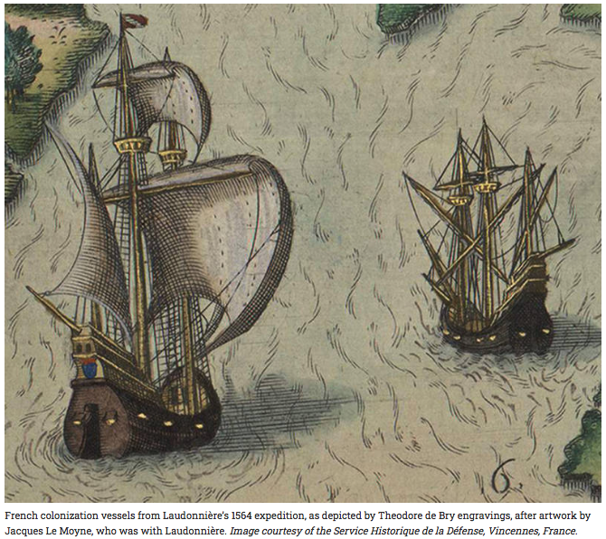
Another alternative for armament configuration is that shown in the depiction below (and a likely accurate one at that), with 6 guns on the lower deck (per side) and one on the deck above astern of the main shrouds - making for a broadside of 7. the higher gun would have extra range, and I've seen (but can't lay hold of right now) two French galleons having 5 guns on the gun deck (per side) and 2 on the deck above (a protected extension of the weather deck). So there are several plausible ways to go, at your discretion, any of which may be valid. An alternative to a pair of guns close to the bow (on the gun deck) would be two of lesser caliber (thus somewhat lighter) located on the forecastle deck (although the space is somewhat limited there), thus still 'at the bow' (bow chasers?). The lighter gun mounts could be angled at will to the side, at a more forward angle, or even ahead if the bowsprit sail was raised (or the yard for it positioned further down on the bowsprit. A lower position of that yard seems preferable anyway, so that the the helmsman manning the whip-staff in his shelter under the small poop deck would have a forward view that cleared the yard on the bowsprit. Once again, there are a number of permutations of options that can fit the period information know.
-
Furled , unfurled or no sails -Preference
Snug Harbor Johnny replied to Canada Steve's topic in Masting, rigging and sails
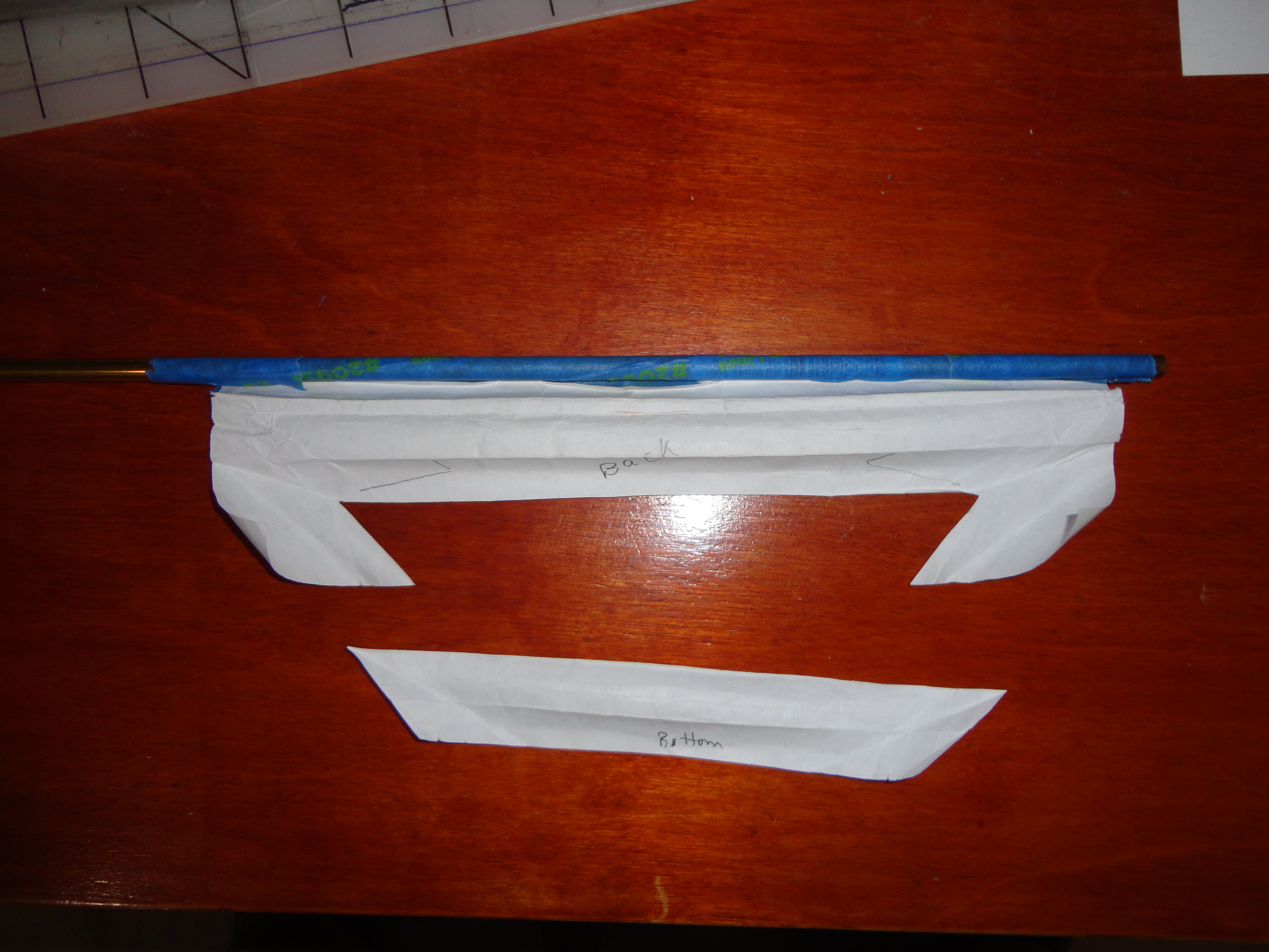
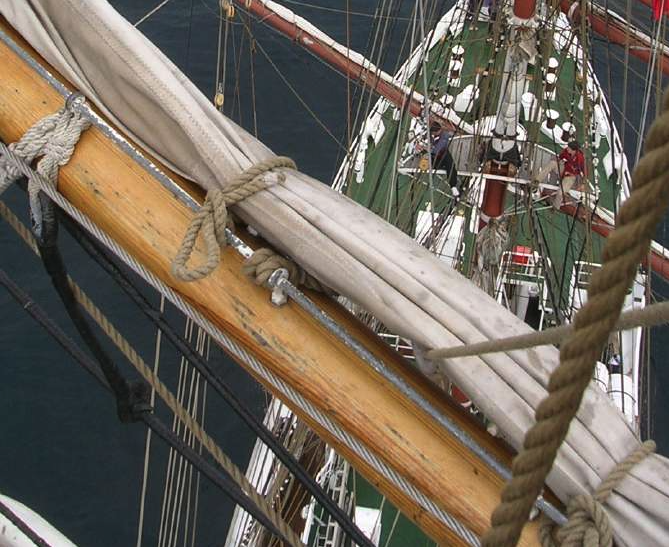
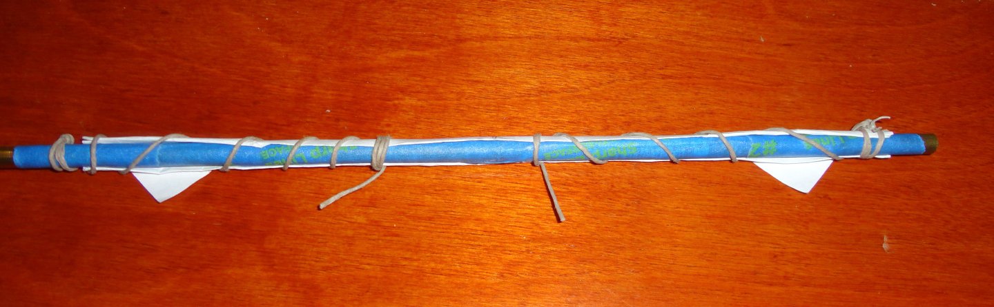
Just look look at 19th c. clipper photos showing furled sails, and its amazing how compact and 'un-bulky' they can be when sitting atop a yard - and there are a couple MSW builds that simulate this. Forget trying to take a cloth sail having the full area, then trying to bunch it. It will only take a narrow strip of thin cloth to look right. The top of the sail where it is bent to the yard or to jackstays is concealed by the folds of the sail plopped on top of the yard, secured by a few gammoning lines. Therefore there is no need to have jackstays at all, or to attach (bend) the bit of cloth to the yard ... no need to worry about reefing lines (and reef tackle can be omitted without much notice - even though it would still be there otherwise) ... and no need to fuss with cringles on a bolt rope or even to sew a bolt rope around the sail perimeter - only on the 'mouse ears' on the clews (bottom sail corners) sticking out, which will be the only sail edges that show. Gasket lines are fastened for quick release as shown below. Before jackstays, one end of the gasket could have an eye splice, and the quick release would be tied after first passing through the eye. No need to include a luff line, and one can have a couple bunt lines emerging from under the folded sail, thus no need for bunt blocks on the yards ... or the bunt lines can be omitted as well - another 'sleight of hand', as there will be plenty of rigging displayed on the model: Lifts for the yards, downhaul tackle where applicable, halyards, clew lines, sheets and braces. Of course, none of this affects the standing rigging done with darker rope. Before furling, the clews are hauled up by deck hands. Men on the yards lean forward and grab partway down the sail (an arms reach) and pull it up and over the top of the yard (leaning back a little as they do this in unison). Then by leaning forward again, that fold of sail is held by body pressure against the yard as another bit of sail is pulled up. Once gathered, the clews are pulled out a bit and allowed to hang. Canvas that is about .025" thick would only be .0005 at 1:48 scale - thinner than a sheet of paper ! So I did a little exercise to tape a strip of paper to a simulated yard, then fold the corners up and then folded the lot (origami style) on top of the "yard" ... and was able to tug out the clews to become 'mouse ears'. Below are a couple pictures of the concept to remove as much cloth as practical to portray a furled sail on a model. Instead of individual gasket lines, I just spiraled a line over the folded paper for convenience. On a model, there would be separate gammons spaced on the yard.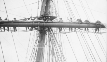

-
Ausgezeichnet !!
-
Ahh, the strong wind and snow called Chinook explains the name of a military twin rotor helicopter used for troop insertion and extraction in Viet Nam. Its powerful down drafts would subject those below to gale force winds driving dust and grit everywhere. So it was known to Grunts as a 'Shithook'.
-
Ahh, the 1:120 version - well thought of by many. I believe included was a second set of yard with the studding sail booms molded in the inward position. With the boom out, sails are recommended,
-
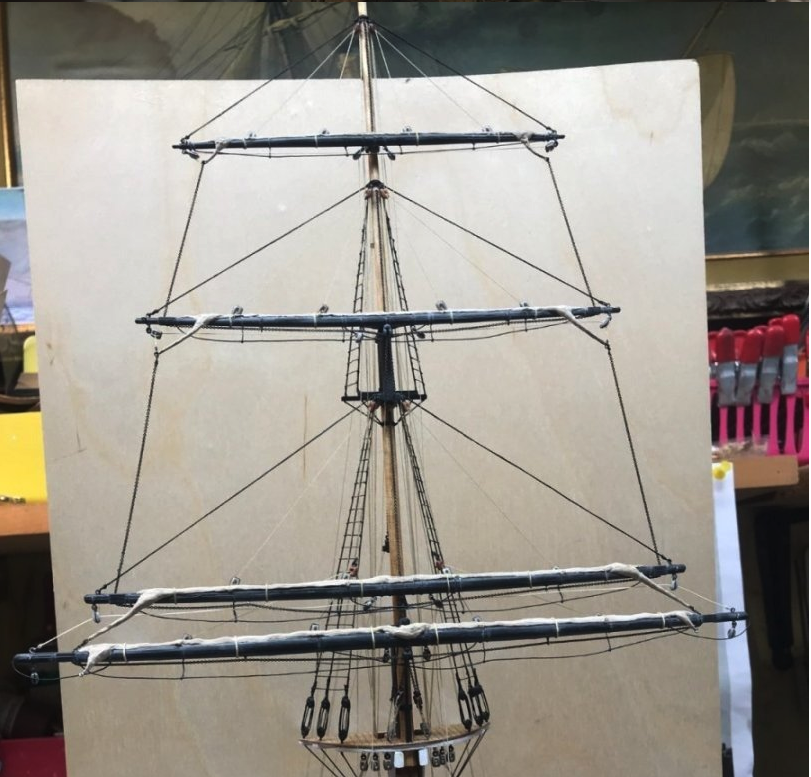
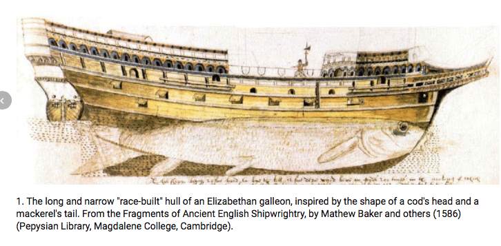
Ahoy Jim ! By 'Captain's walkway' (a modern term?) I mean the 'wrap-around' gallery, or promenade that goes around the stern ... nothing to do with a quarterdeck or even a poop deck. The wrap-around walkway was present on many Spanish ship and on larger warships of various nations. Poking around, there is an entry in the Plymouth Black Book concerning Drake building the Pelican at Plymouth in 1575. His circumnavigation (after a couple false starts) began from Plymouth in January of 1578 - so the Pelican (to become the Golden Hind later) was about 2 1/2 years old, and 3 years old by the time Da Silva saw it, ergo it was not 'new'. Since it looked 'French" to Da Silva, it was most likely the latest "race built" type first adopted by the French. The term 'race' was from the French rase' - meaning shaved - in that the poop deck was removed. You show a number of artists' depictions of the vessel that are modern, or well beyond the 16th century. You have to take them as conjectural, all with likely good points - some getting closer to the mark, just as the more darts you throw at a dartboard the better your chances of getting one near the center. Weighting the period testimony and period drawings more heavily, I think the (half scale) sailing version photo you posted come very near to the mark. The Baker log has many great details, and should be looked at for tips and techniques. In the end, no one can say for sure 'exactly' what the GH looked like. But then most ships go through many modifications, and as experience builder note, one should try and portray a given time in a vessel's life (e.g., Polris before Shackleton bought it, as modified in England before the expedition, as modified in South America before setting out for Antartica, and stuck on the ice shelf prior to sinking. Each will have a different appearance.) Ergo, the way GH looked on the big voyage may well have been modified after the return so there could be a big show the next year when the French Ambassador dubbed Drake a Knight in the presence of Queen Elizabeth (my mistake to think she did the dubbing herself, since that might seem to put too much honor on who the Spanish considered a pirate) aboard a refurbished GH. So one could imagine a lot of added decoration and pre haps a stern walkway as well ...
-
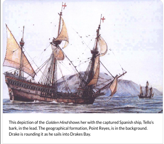
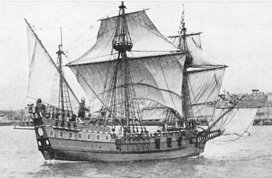
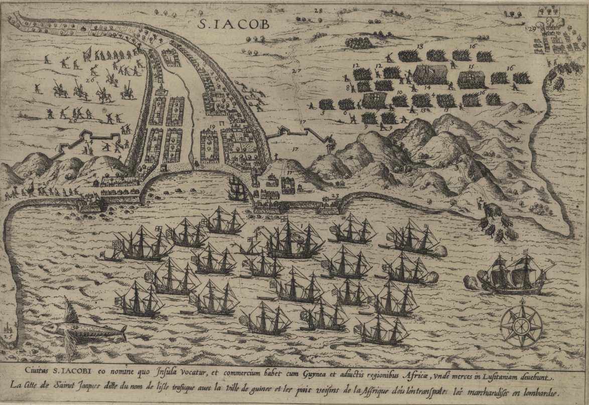
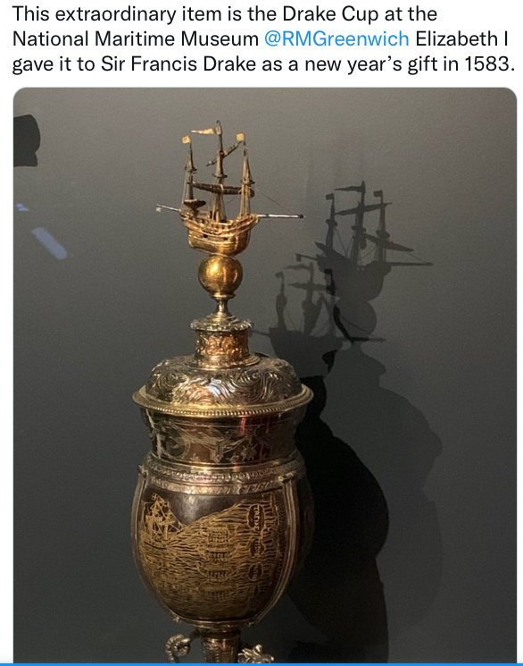
I did some research a while back (buried now in my papers somewhere ... and I've commented in another build log in the past, which might be hard for me to find) on the most likely configuration of the Golden Hind (GH), which has long been depicted with great variation as to size, armaments, decoration, etc. - in that the original is long gone and with out a definitive artist's sketch or painting naming it. The recorded testimony of Nuno Da Silva (the Portuguese navigator capture by Drake on his circumnavigation) to the Spanish authorities and also to the Inquisition provide information on the GH by someone qualified to make those assessments. Reading a translation of the entire documents was a fascinating account of the voyage from the Caribbean to the West coast of Mexico, where Da Silva was let off. He stated that the GH was 220 tons (in Old Portuguese tons), and that converts to about 180 modern tons. The size of the GH was about the size of the modern replica you have posted photos of (102' on deck) ... except ... note the bulging nacelles added at the waterline that were needed to make the replica seaworthy. The 'as built' replica with a 20' beam proved unseaworthy, and the effective addition of a couple feet on either side at the waterline solved the problem - and point to a proper beam of 24 - 25 feet at the waterline. This would have added more breadth on deck, as the hull lines would flow smoothly up from the waterline with some tumblehome. Da Silva stated the broadside was 7 guns per side through gun ports, plus 4 at the bows (2 astern as typical, and 2 forward), and that the ship was not new and of French style. You note the problems that would exist trying to load cannon on the weather deck, and Da Silva testified that they were all below (thus having enough room to operate fully, protected from the weather and adding stability to the ship by lowering the center of gravity). So only some anti-personnel rail guns may have been above deck. Some contemporary depictions are included below: Note that there are no 'Captain's walk' on any of the above (or below) depictions. In the Elizabethan picture above, there is a broadside of 7 (the hatch below the row of gun ports may be a 'communication' port - much like the one on the Warship Vasa. There are 2 guns astern, and note the port for a forward firing gun at the bow (there would be another on the port side) - also like the ones on the Vasa. This is very likely what the GH hull looked like. The high angle of the bowsprit at that time would keep the bowsprit yard with sail above the line of sight of the near-forward pointing gun ports. Above is a depiction of Drakes 'Caribbean Fleet' (a later venture), and none of the ships have a Captains walk - not even the largest (one anchored and one entering). The ship entering (firing a salute from the aforementioned forward guns) would be like the GH. The Drake cup, the base of which is from a coconut given to the Queen by Drake, given back to Drake as a gift from the Queen, has a 3D silver miniature GH on the lid, as well as an engraved GH on the bowl from an episode of the circumnavigation. There is no Captain's walk on either. Spanish ships of that era (and some other nationalities) did have captains walks, and there are pictures of these extant. My theory is that they look fancier, and so later artists depicting the GH (then a ship of fame) with such a stern walkway because ... it just looks better. The condition of the GH, that barely was able to limp home with treasure aboard, was likely poor. So perhaps in the time between the ship's return and the knighting ceremony for Drake in a new docking place on the Thames, the GH was spruced up a bit up the Deptford creek and had any ornamentation re-painted - or even expanded upon. The name change from Pelican to GH happened during the voyage, so the idea of a gilded hind as a figurehead (as well as elaborate E.R. and heraldry on the stern) seem either artistic license, or something added after the voyage.

-
New Member - Some modeling experience
Snug Harbor Johnny replied to Dave Wells's topic in New member Introductions
Welcome aboard mate ! Let' see ... 5/64 is not used much these days as a 'scale', so I'll have to try and figure. If the cannon is 5/8" long, that would be .625". Now in the scale of 1:128 (not uncommon in "old' kits, like Scientific models sold in the 70s) .625 x 128 = 80" ... or 6 feet 8inches long ... perhaps a plausible size. Looking on line at a data point (if it is the same Essex) a hull of 185' at 1:128 scale would be about 17.3" ... (185/128 x 12) also a plausible model size. So if MS doesn't have anything suitable, (and my educated guesses are right) you might try looking on line for model cannons that are 1:128 scale.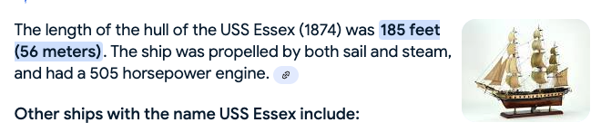
-
Case or no case?
Snug Harbor Johnny replied to Bill97's topic in Modeling tools and Workshop Equipment
I noticed the high price of plexiglass also ... but saw that thinner (and less heavy) acrylic sheets were much less. So when I suggested acrylic, I wasn't referring to the higher priced polycarbonate (plexiglass). Glbarlow said that his models are not behind a barrier, and that he uses a gentle blower (perhaps a hair dryer blowing at low speed without heat) at intervals (quarterly?) to keep dust from accumulating. This is something I might try first, before going to the trouble to install any acrylic. This is because our home has forced air HVAC for heating/cooling, and there is a BIG pre-filter that has an accordion shape for more surface area (the kind that removes allergens pollen) right before the air circulator. I change this at least twice a year, and order replacement filters in a carton with 4 - and they cost $35 each (much lower than either the HAVAC man or retail). The air handler runs continuously - which is better for the heating/cooling system and house comfort as well. Its amazing how much stuff is taken out of the air by the filter. -
Case or no case?
Snug Harbor Johnny replied to Bill97's topic in Modeling tools and Workshop Equipment
I've pondered of this situation before, and thought of one approach to try in our parlor. A long shelf would be installed along one wall, perhaps just above 'chair rail' height, using brackets available in most home centers. The brackets would be fastened into the studs behind the wall, found with a stud finder - they are generally spaced at 16" intervals, but can vary. Wood shelving would lie on the brackets (and there are often a variety of available finishes - or fashion your own). To get the length required, shelf ends can be held together on on the underside using thin metal joining strips fastened with short screws. Then a little above the tallest ship to go on that level, another long shelf is installed above ... and one could perhaps have three levels to display models. At intervals on the front edges of the shelving would be spaced small threaded rods with the outside ends bent 90 degrees to make an "L" shape. One could hang acrylic sheets from these retainers (through holes drilled into the acrylic), and each piece would be trimmed just long enough to cover the gap between the shelves (there would be a clear panel on the ends of the shelves. This arrangement would keep out most of the dust and provide a good view of the models, yet the models would be easily accessible by lifting and removing the acrylic sheet in front. It would also be easy to re-arrange the display as desired. -
Rather than try to modify some of the bulkheads before assembly, assemble them first and then deal with any bulges in the "fairing" process. If you flex a piece of thin, straight spring wire stock over the bulkheads, it will be easy to see any bulge. Then by sanding and frequently re-checking with the wire, you can achieve smooth lines/transitions.
-
My bearding line is where I stop shaving ... 😉 'Don't think 1.5mm (about 0.060") will make much difference, but you're likely to reduce the frames a bit when fairing, and then there is liberal sanding of the first planking to perfect the lines - which will take more off the thickness (just don't sand through). Thus you can easily whittle down the difference to 0.75mm without fretting over the frames.
-
'Haven't even thought about lights ... No builders have said a thing about them above deck (or anywhere), and so far no above deck photos have been pointed out to show any. Below deck there were lights, but only a 'cutaway' model would have them ...
-
Whatever you produce, I’d be interested in. I have had this kit for two years - and initially did a kit review because of the overall value to an intermediate modeler. I studied the known lines of the original hull, and found that the kit bulkheads can be easily altered (if desired) near the bow (to reduce the flare slightly) and stern (for a little more fullness). I’ve followed every build of Endurace with interest to see every modification that could be considered when I eventually do it myself. The kit configuration appears to be as it set sail from South America - with a covered steering mechanism and the dog kennels. I bought 3D brass stanchions for the railings (an upgrade from the PE verticals), as well as better deadeyes and blocks … also a Rope Rocket from Syren to make my own scale rope, and a 2 bladed screw. The 3 bladed propeller provided came in handy for the Gorch Fock restoration in progress - to gain better familiarity with rigging. So whenever you make extra 3D items, feel free to private message me to make any arrangement. Smooth sailing, mate ! Johnny