Snug Harbor Johnny
-
Posts
1,510 -
Joined
-
Last visited
Content Type
Profiles
Forums
Gallery
Events
Everything posted by Snug Harbor Johnny
-
Ahoy Captain! You don't need to post any logs to enjoy and learn all about the hobby (and historic ships as well) at MSW. I dare say your Unimat should come in handy for turning small parts in brass or wood (as I have done with a 3-jaw universal chuck on mine).
-
'Looked over builds of both the M.S. 1:64 Bluenose I and the A.L. Bluenose II 1:75, and concluded that the A.L. kit has somewhat easier hull construction. The bulwarks are a single applied piece ... the build by Travis notes the slight bulkhead correction needed in one place, as well as the addition of a small triangular piece at the bow (later hidden by a larger piece of trim) that will better secure the bow joint of the bulwarks. This feature permits the application of correct sized stanchions along the interior of the bulwark where they need to go. I noted how Travis applied the thin fore keel during the planking process, and other helpful aspects of the build. The model is a good compromise size. The builder needs to download the instructions and there are no drawings. The M.S. kit makes a somewhat larger model (ergo larger case required later), and has planked bulwarks against extensions of the bulkheads. Many kits have it this way, and requires shaving to get the correct size of stanchions that will not stand out from added stanchions in between. The kit has better instructions and there are drawings, but the level of difficulty is somewhat higher overall. I decided to go with the A.L. kit (now in my stash) in conjunction with the Jensen book (to use as a guide - making up for the lack of information connected with the kit) for a future retirement project. There are smaller scales of Bluenose kits available that I wanted to avoid, since the 1:96 projects I have to finish get fiddly with correct sized rigging blocks, belaying pins, etc.
-
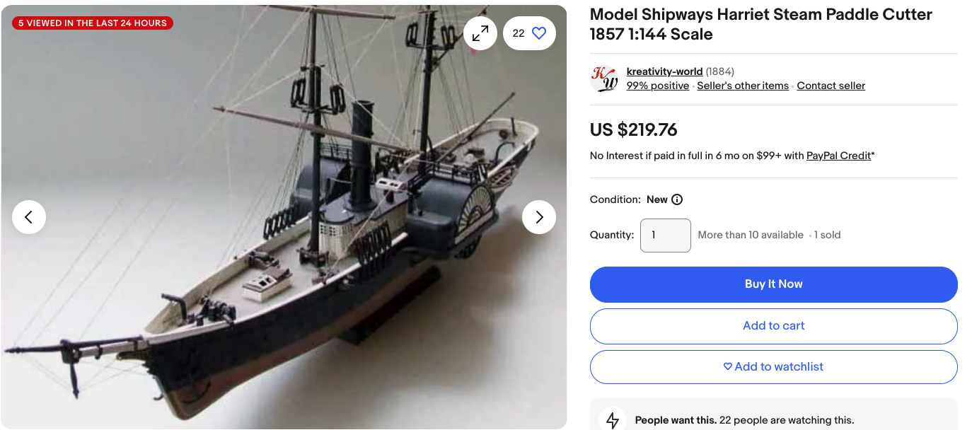
I've gone through the builds of the Harriet Lane available on two forums, and it has several things going for it ... an interesting transitional Coast Guard Cutter with both steam (side wheels) and sail - but not too much sail; there are guns - but not too many of them; a decent size model - but not too large; decent plans and instructions from Model Shipways - a well thought-of kit maker. The only oddity I've seen is that most builders find that the guns hit the top of the gunport (bottom of the gunwale) and tilt slightly downward. 'Not sure how this anomaly occurred, and the gun barrels have been verified as being to scale. The easiest 'fix' deals with the height of the gun carriages - and the bottoms can be sanded down (just run over sandpaper on a flat surface) before fixing the axles (with the notches for the axles deepened accordingly). That will lower the front of the gun carriages enough so that the gun barrels will point horizontally. Forewarned is forearmed, and other than this small fix, the kit look appropriate for your trajectory. Pricing and availability vary, but I attach a picture (below) of one on eBay just now. Another suggestion is Artesania Latina's Bluenose 2 1:75 (with caveat). They've simplified a number of details to make it appropriate for a fair spread of ability. The 'fix' is to get a copy of L.B.Jensen's hand drawn book "Bluenose II", which has everything needed to vastly improve the details and rigging from an 'out of the box' build, and you are capable of doing upgrades. OR, Model Shipways has a 1:64 Bluenose (original) ... slightly larger and of the original ship built in 1921. And the Jensen book has diagrams of that as well, plus the rigging is virtually identical. She's a schooner but (with the book to supplement instructions) you'll learn a lot about fore-and-aft rigging without having do deal with the well over 100+ lines of a clipper.

-
 Wow, the water door appear to be simple plates (with a pair of small hinges at the top) with a low profile that simply close against openings in the steel bulwarks. Gravity keeps them closed, or nearly so, but a slight tilt of the hull will open them a little. No scuppers are seen (or needed), and a CS modeler can imitate them by gluing a thin square of material to the outside, with a rebate on the inside (square hole in the first planking layer) to represent the opening in the bulwark that the water door covers on the outside. Thermie had wooden bulwarks, so I suppose the rebate would deeper.
 -
Very impressive - a veritable compendium of sources ... The most recent (and more easily accessible) are still those by Anderson Petersson and Underhill.
-
For warships from the mid 1700s to the 1850s, check out 'Rigging Period Ship Models' by Lennarth Peterson ... first published in 2000, and reprinted in 2011, 2014, 2016 and 2018 (so is likely still in print). After the introduction, every page is a generous line drawn illustration of some aspect of rigging (labels and terms in English) from the standing rigging on out through full sail. There are other diagrams for belaying points, etc. This is the clearest, concise guide I've yet seen, and indeed - one picture is worth a thousand words. The scale of detail is varied as needed to convey pretty much 'how to do it', and I suppose that many of the elements can be applied to non-military square rigged ships of that era. I dare say that if one were allowed only ONE reference book for rigging a ship in the subject period this would be the one I'd pick ... virtually no text, but they show you in pictures - thus suitable for non-English speakers (who can likely use a translation app on their smart phone for the labels). Samuel Clemens (aka Mark Twain) said to would-be writers, "Don't tell them, SHOW them."
-
Thats a cool lantern and a well built model ... Kudos!
-
I love the bead at the mast top ! ... something I'll copy later. Now you are embarking on the "other" half of building the model ... the rigging. Have you considered using scale rope? Several sizes and colors are easily available and can really make rigging look sharp (way less fuzz and realistic look). Some builders also run kit blocks a few seconds in a block sander to 'round' the sharp edges somewhat, as well as use a fine drill to be sure the through hole is clear for ease of rigging ... or consider Syren blocks as an upgrade.
-
Even more profitable (for most) was to 'mine' the prospectors by offering wildly overpriced supplies. If you shipped tools and necessities to San Fransisco during the gold rush, you could get thirty to 50 times what you paid for the stuff in the East.
-
'Sorry to be off topic, but there IS a tiger (and others) that one can see (perhaps for free one day of the year) in the U.S. There used to be an extensive tank collection outdoors at the Aberdeen Proving Grounds in Maryland (USA), but in 2012 everything was moved to Fort Lee Virginia (temporarily) ... and ended up in the U.S. Armor and Cavalry Collection in Mort Moore Georgia - said to be largest collection of historic armored vehicles in the world. It is NOT open to the public in general (bummer), but has an open house at least once a year - the last one being September 7th this year. So its not all bad news. The Aberdeen collection was deteriorating outdoors anyway, but while still at Aberdeen I could climb inside several of the big German tanks - and a picture of one is below that I was inside ... I recognize the hit on the gun mantle. There are tanks assembled from a number of locations now under roofs, and many have been stabilized with new paint - probably the best for future viewing and reference. for a tour, see:


-
I love this idea ... especially because a.) CS had triple planking (ergo it is plausible if not likely that Big T had the same) and b.) the 45 degree angle will give great strength (probably why it was done). After the second planking, you can cut the square ports for the 'water doors' without endangering the stability of the bulwark planking. Then the final fore-and-aft plank layer will come up just short of the water port, which will provide the bearing surface of the water door to close against (being hinged on the top). Rob pointed out that great seas could often pour over the gunwale going around the Horn, then the weight of the water would tilt the water doors outward to permit quick discharge of the water sloshed on deck. The doors were metal, so their own weight would close them ... any wave hitting against the door would simply press it against the rebait planking behind the door without shipping water. Whatever water remaining would just run out through the scuppers. Wow, one can learn something new every day ! EDIT: Now I see that the CS doesn't have tiny scuppers (Probably because the bulwarks were steel plate), so the water doors do the entire job. The Big T had wooden bulwarks, so she might have had a few scuppers like very many wooden ships of the day. Perhaps close examination of what photos are available might be indicative. FWIW, a scupper with a 4" (100mm) opening would only be 1mm (0.0395") at 1:100, ergo on my 1:96 projects that is pretty small indeed to fool with, although a section from a 'blunt fill' injection needle (used in our hospital Pharmacy to reconstitute medications for I.V.bags) might serve.
-
'Must have been a 'tub' to sail in back in the day ... still cute !
-
Very neat ratlines, and everything's in black (including deadeye lacings) like they should be.
- 431 replies
-
- 2
-

-
- Flying Fish
- Model Shipways
- (and 2 more)
-
Come aboard, mate !
-
'Depends on the type of ship ... For square rigged commercial vessels, 'Masting & Rigging the Clipper Ship & Ocean Carrier' by Harold A. Underhill - 1946 (available as a pre-owned book) has a wealth of information, much of it applying to the 1850s, when patents for splitting the top sail were being adopted. The time range applies from the late 1840s through the early 20th century. For many sailing warships, 'Rigging Period Ship Models by Lennarth Petersson has material applicable from roughly 1800 through the 1850s (e.g. the rebuild of the U.S.S. Constellation). A different kettle of fish from commercial vessels. There are a couple of books on fore-and-aft type ships (e.g. schooners), but the name of them escapes me at this moment (Edit: one of them may be Underhill's 'Sailing Ship Rigs and Rigging' 1955 , that covers additional ship types). However, I find that 'The Bluenose II' by L.B. Jenson (who also documents the original Bluenose of 1921 - the rigging virtually the same) has much information that might be applicable for earlier schooners. Again, fore-and-aft rigging is a different kettle of fish from the above two classes. EDIT: R.C. Anderson '17th Century Rigging' (1952) expands the time period somewhat, and provides further insight. Anderson's 'The Rigging of Ships - In the Days of the Spritsail Topmast 1600- 1720' (1984) further stretches the time period and ship type.
-
Fantastic save, mate ! Just shows what one can do when working in wood.
- 110 replies
-
- 7
-
-
- Paddlewheeler
- Ballarat
- (and 3 more)
-
For the lion's heads on the inside of Vasa's gun port lids, I made a master - then poured a two-part silicone resin over it. Once cured, the mold is flexible and the original popped out (the base being flat). Duplicates are done in two-part epoxy put into the mold and drawn flat against the back surface of the mold.
- 445 replies
-
- 1
-
-
- soleil royal
- Heller
- (and 1 more)
-
O M Gosh, Simon ... 'could have been far worse. The thing I like working in wood is that all kinds of repairs and modifications are possible - 'just take patience and glue. You are coming along nicely, mate !
-
Byrnes table saw motor
Snug Harbor Johnny replied to jbeyl's topic in Modeling tools and Workshop Equipment
I'm told that the problem with capacitors in general is that they do tend to go bad eventually - being not a matter of 'if', but a matter of 'when'. -
Another detail I've just noticed in the dramatic artwork (as my attention was drawn elsewhere in the painting) ... The sails that have already been furled have the mouse ears clewed to the mast in 'Navy fashion' ... very interesting. Commercial ships often have the 'ears' positioned near the ends of the yards. But ships can be rigged however the Captain prefers, so this one might have been a Navy man.
-
Superb !
-
Fair question but ... everything is relative. $16 vs $30 is large expressed as a percentage, but then $14 does not represent a 'lot' of money per se. You obviously want the best tool for the purpose, so if the cheaper one turned out to have disadvantages - you wouldn't be happy with it compared to the other. Soooo ... the $14 question is Which one is better? Now below I've pasted a Youtube where a guy compares both. He starts out noting what he considers to be the main deficiency of the Tandy when it comes to cutting thick leather strap - and that is breakage of blade or wood with use. He manipulates a sketch (cleverly) to demonstrate the differences - but the wood on either side of the blade on the cheaper tool is exaggerated in the sketch when compared to what is actually on the tool. If you watch the whole video, his opinion keeps going DOWN concerning the cheaper tool due to a couple of things: 1.) the possible gap (to accommodate different stock thicknesses) is WAY less on the cheaper one. 2.) even though the end knob looks better than the metal thumbscrew of the Tandy, there is almost NO adjustment on the cheaper one. 3.) the blades on the cheaper one are non-standard, with no indication of haw to get replacements (although they can doubtlessly be honed as needed) 4.) He doesn't like the 'feel' and lighter weight of the cheaper one - probably like comparing hickory with something more akin to basswood. His conclusion is that the Tandy is superior. 5.) The cheaper blade sticks out a lot both top and bottom ... and this seems dangerous - at least a slip could cause a nasty cut ... whereas the Tandy blade is entirely covered by the reinforcing plates. 6.) the end screws are easily adjusted with a screw driver on the Tandy, compared to the the need of a hex key (not included0 for the cheaper tool. At the end of the video, the guy says he wants to send the cheaper one back. Now I realize that the application at hand is to trim the width of relative thin stock used for planking ... so having a more limited thickness capability on the cheaper tool would not be a disadvantage compared to a user who wants to cut thicker leather. I also note that there will be far less force to trim planking stock than to cut thick leather, so the wood in question on the tool would not be likely to break. The available wood on my own stript-easer is even LESS, but there has never been breakage. I also note that there are metal re-enforcing plates top and bottom on the Tandy tool, that is adjusted, make breakage unlikely. Once can just as easily glue reinforcement wood to the leading edge of the Tandy jig if one has any doubt. The Tandy blades have available replacements (if one does not want to hone occasionally), and they are not as wide as the cheaper ones. This will permit the mounting of the Tandy blade at an angle (before tightening), which I've always found to be an advantage. Since the application at hand is for thinner stock, so it is unlikely that blade breakage will be a problem. After all, the guy in the video was running LOTs of 1/4" belt leather (for commercial purposes) through the Tandy tool. If the greater width of the cheaper blade would hold up better for thick stock, the inability of getting a thicker gap between the horizontal pieces effectively nullify any advantage in maximum blade strength. As for me, I'm going to try the Tandy. But each individual should make a choice based on their own tastes and preferences. https://www.google.com/search?q=reviews+of+craftool+strap+cutter&rlz=1C5MACD_enUS1049US1049&oq=reviews+of+craftool+starp&aqs=chrome.3.69i57j33i10i160l2j33i299j33i671.11968j0j7&sourceid=chrome&ie=UTF-8#fpstate=ive&vld=cid:484cd395,vid:y4ATkSRR-Nw,st:0
-
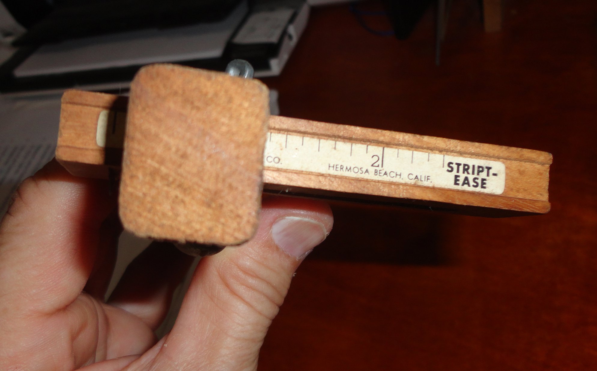
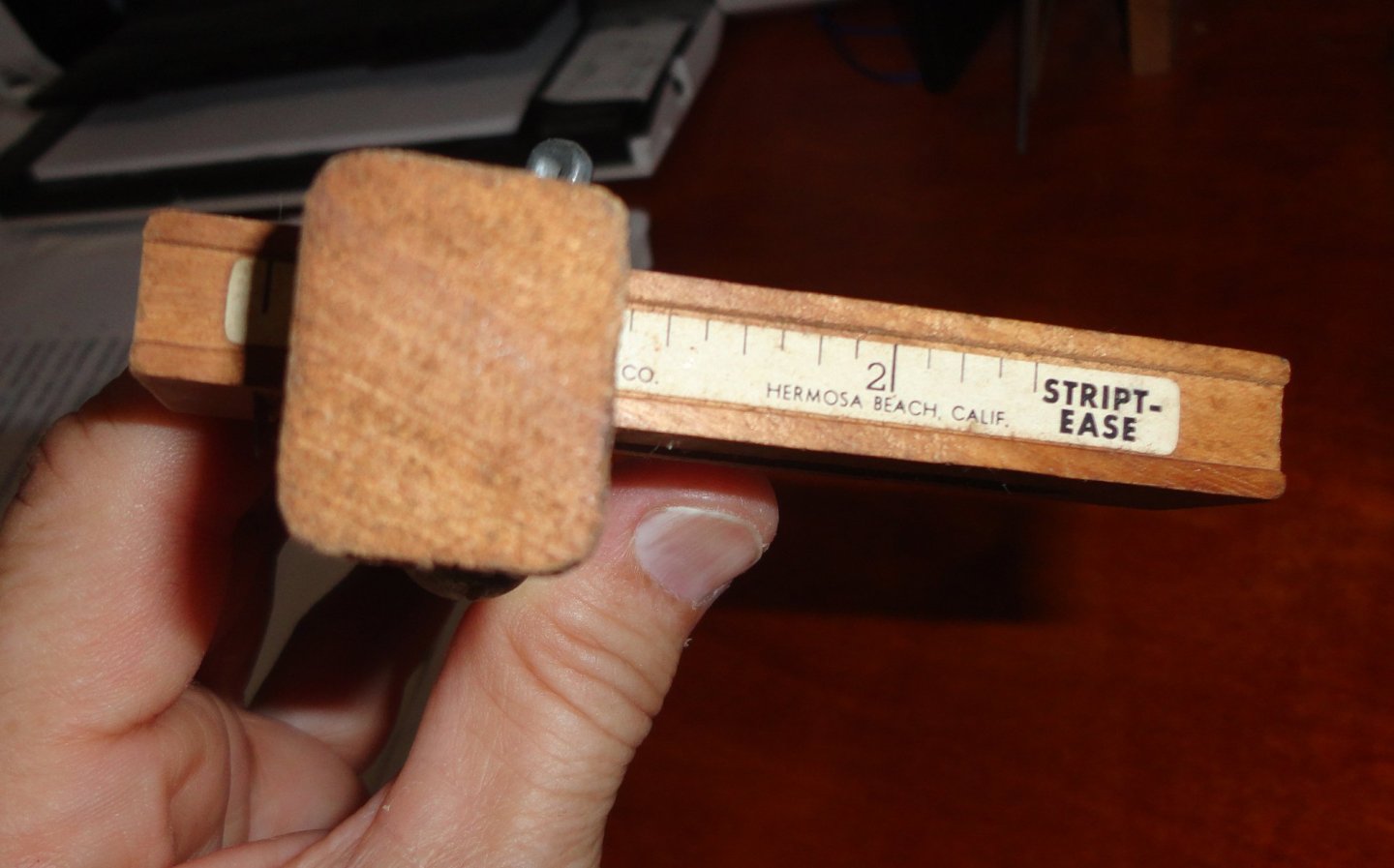
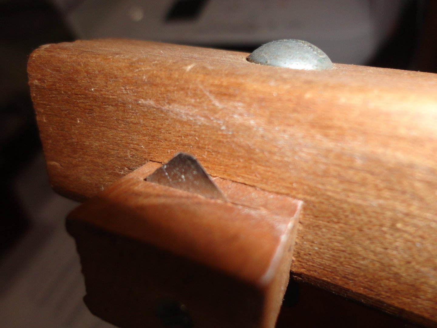
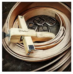
Tandy leather used to offer a tool called the 'stript - ease' - pictured below (I still use mine). It is for cutting uniform width strips of leather - and if you start with either a round (or rounded edge oblong) piece of leather, you can make a very long continuous thong or even pretty narrow lacing leather. The second picture shows how I set the bit of razor blade at an angle ... seemed to cut better - like using a block plane at a 'skewed' angle. This tool is not available (leather crafts are not as popular as they once were - and Tandy stores were close when they went to online sales), and one might be on eBay ... However, there IS a strip cutter online on the Tandy site called the Craftool Strip Cutter (third picture below). It might actually be a better tool, since there is a pair of outriggers (adjustable for the stock thickness). This may keep the stock from lifting up, which I find happens with the original cutter - depending on how one holds the stock. With either jig, for cutting wood, you have to be mindful how the grain runs - and only trim the side where any grain rises away from the cutter. That way, it won't 'dig in' to the stock as it may if one cuts into 'diving' grain. This also can happen if too much wood is being trimmed (trying to save time). Marking the strip stocks to be narrowed with a penciled arrow can prevent accidentally reversin the stock from the way you need to draw it through. The way to narrow wood strips is to take several light cuts, where all the stock you want narrowed is passed through the jig taking off a quarter mm or so. Then adjust to take a little more, until you get the strip width wanted. I used to teach handicrafts at a summer camp, so I inventoried the cutter as a 'stripteaser' ... Johnny
-
OcCre Bounty Launch parts ID - help needed
Snug Harbor Johnny replied to Highlander's topic in Wood ship model kits
Heck, when confused I'll often just 'wing it' and use whatever is handy to make a project 'look right'. -
A SUPER build ! The lighting is effective. I can picture this display in a museum ...