


Snug Harbor Johnny
-
Posts
1,511 -
Joined
-
Last visited
Content Type
Profiles
Forums
Gallery
Events
Everything posted by Snug Harbor Johnny
-
 'Haven't even thought about lights ... No builders have said a thing about them above deck (or anywhere), and so far no above deck photos have been pointed out to show any. Below deck there were lights, but only a 'cutaway' model would have them ...
 -
Whatever you produce, I’d be interested in. I have had this kit for two years - and initially did a kit review because of the overall value to an intermediate modeler. I studied the known lines of the original hull, and found that the kit bulkheads can be easily altered (if desired) near the bow (to reduce the flare slightly) and stern (for a little more fullness). I’ve followed every build of Endurace with interest to see every modification that could be considered when I eventually do it myself. The kit configuration appears to be as it set sail from South America - with a covered steering mechanism and the dog kennels. I bought 3D brass stanchions for the railings (an upgrade from the PE verticals), as well as better deadeyes and blocks … also a Rope Rocket from Syren to make my own scale rope, and a 2 bladed screw. The 3 bladed propeller provided came in handy for the Gorch Fock restoration in progress - to gain better familiarity with rigging. So whenever you make extra 3D items, feel free to private message me to make any arrangement. Smooth sailing, mate ! Johnny
-
Very cool, those 3D items you printed. Have you considered selling 'upgrade' sets for this kit to fellow members? I'd certainly be game, as the cost and learning curve of 3D printing are not on the horizon, and not everyone wants to 're-invent' the wheel, so to speak.
-
When railing and shields are mounted atop the stern castle, the balance with the fore castle height will be fine.
-
'Looks like you're going to leave the "Captain's walk" on ... I suppose when the original was repainted and fancied-up prior to the Queen Knighting Drake, they might have added one for show. Her saving it 'for posterity' (so Queen Elizabeth thought at the time) made it the second 'museum ship' in history - the first being the ship of Theseus in ancient Athens, which was continually repaired with new wood for hundreds of years ... until none of the original wood remained. This led to the logic problem of, 'is it really the ship of Theseus ?'. The GH was in such bad shape in, what, 60 or so years that what was left got buried in situ. I've wondered why there has been no effort to do archeology in what is thought to be her resting place using modern techniques. That would likely reveal the hull lines and gunport locations, as well as settle the question about the Captain's walk.
- 30 replies
-
- 2
-

-
- Golden Hind
- Airfix
- (and 1 more)
-
I'd loathe drilling a hole through a relatively thin mast section to accommodate a halyard ... even if that is 'called for'. That creates a weak point, unless that portion is reinforced by a metal collar. I'm opting for a pair of blocks on either side (jeers fashion), with the line in one continuous piece that goes through a block (for a single halyard) on the other side ... for a project still being mulled over.
- 431 replies
-
- 1
-
-
- Flying Fish
- Model Shipways
- (and 2 more)
-
Will there be any latrine holes in the bottom of the forecastle ? Obviously, the heads will be concealed within the structure, so there's no need to construct the seats ... unless you want to - in case anyone wants to examine the underside of the forecastle using a mirror. Hmmm, kinda like some show cars where the undercarriage gets painted-up nice and they show it off with a mirror on top of a wheeled floor jack.
-
Now the Mary Rose was built way before there was anything like a Sears catalog, but a source indicates that in Roman times there was a sponge on a stick placed in a water bucket at the latrines, and all the men used the same implement to clean themselves. Maybe there was something like that in Henry's time.
-
What can you put in a barrel and make it lighter? ... Holes 😉
-
Remains of 500 year-old shipwreck: Dated 2019
Snug Harbor Johnny replied to Allegheny's topic in Nautical/Naval History
Even if the Mary Rose Forecastle was in pieces, they could still put the 'jigsaw' back together with sufficient funding. -
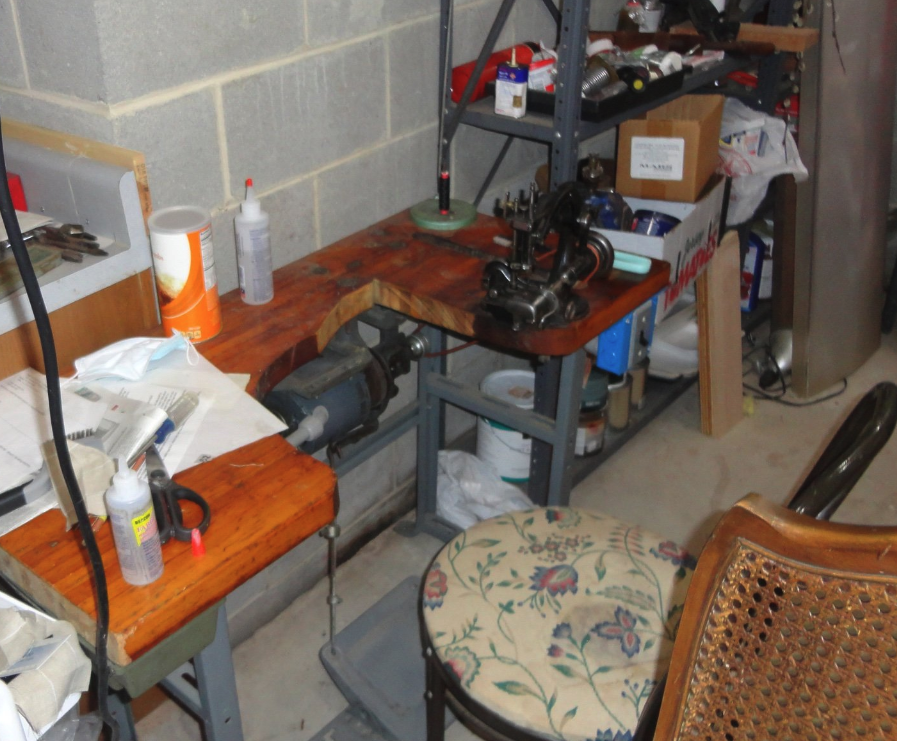
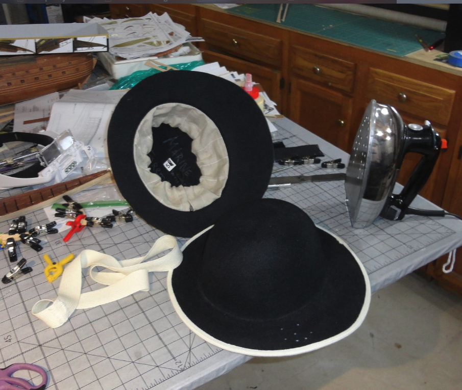
You can find something uncommon on Amazon or eBay by looking every day ... takes a schedule, and may take weeks or months - but don't you know, in time what you're looking for may pop up (on eBay more likely - but with books , second hand sellers do log new items as they get them ... otherwise they'd run out of books to sell). Case in point: I needed to find a hat band sewing machine - the kind with a very HIGH throat to accommodate the wide brim of 'old time' hats. This is because I took on piecework to make repro Colonial soldiers' hats (tricorns), and was having a heck of a time sewing linen sweatbands inside the crown on a regular sewing machine. Since a lot of hat manufacture went overseas, so did a lot of the machines to to the work ... and those still in the U.S. are closely held. A classic Singer would have been preferred, but a Wilcox and Gibbs chain stitch machine would do (with going around twice incase someone wanted to monkey with either 'loose' thread at the beginning or end, which are needed to 'lock' the stitching. Pull the wrong thing and a whole line of sewing can come undone, explaining why some Civil War soldier uniform components that were not mended promptly would come apart ... blamed on 'shoddy' work, but procurers contracted with low bidders who bought loop machines that cost half of what lockstitch machines were going for. Anyway, I looked faithfully for over a year, and finally - on eBay ... a small concern way out on Long Island N.Y. was selling off two chain stitch machines. I bought one and drove up immediately to pick the better one. Even then, I had to do a lot of work on it to go into production. The moral is that patience can pay off ... sort of like fishing on a slow day.
-
Since the forecastle houses the 'heads', do you want to cut out waste holes for, say, a three-holer on each side? Having to carry waste out in buckets to throw over the side is a non-value added activity ... and risks soiling the side of the hull - or slipping in heavy swells and spilling it over the deck!
-
Ratline thread recommendations 1/75 scale
Snug Harbor Johnny replied to John AA's topic in Masting, rigging and sails
Keith is right, as I've used both Gutermann versus Mettler poly on the Siren 'Rope Rocket', and found Gutermann has minimal 'fuzz'. Making rope is cheaper, and you can customize it as needed by changing the number of threads in the 'set-up' ... but it is a process you have to learn to 'get right', takes time to do, and the length is limited by the room available. So I can understand buying rope from the available sources. Builders put so much time and effort into their models, so its a wonder that some will use 'fuzzy' rigging thread that does not have the nice definition that spun scale rope has. Photo close-ups DO accentuate the fuzz, which is less noticeable at a distance. BUT, a model made by my dad 70 years ago had rigging made of cotton thread that just disintegrated all by itself. Parts held by thread either fell apart, and rigging crumbled by the slightest touch. This was told to me after the fact by the brother who had the clipper model, and since he thought it a total loss - the model was trashed. Had I known this before he made that decision, I could have offered to replace all the rigging with poly scale rope - a bit of trouble, but worth it for an heirloom. -
New member, happy to be here
Snug Harbor Johnny replied to Joanie's topic in New member Introductions
Ahoy Joanie ! 'Glad to have you aboard. You've done VERY well so far, and I understand your frustrations that the instructions and illustrations in the Billing kit are somewhat lean. But I have a suggestion to offer that will come in most handy at the stage of the build you are in. It is a book (now out of print, but a copy can be found on-line ... I got mine through Amazon.) It is "Bluenose II - Saga of the Great Fishing Schooners" by L.B. Jenson published by Nimbus (1994) ... Soft cover 11 x 14 format of the original hand drafted drawings with cursive text. Don't be put off that the subject is the Bluenose 2, as the author has included hull drawings of Bluenose (I) on pp.66-67 - and notes that the masting and rigging of the two schooners were virtually identical. So the copious and detailed drawings of everything above deck level (sails, rigging, blocks, etc.) are perfectly useable for both Bluenose and Bluenose II. (As can be found today on-line, there was a controversial 're-build' of Bluenose II where many changes were made, although the 'new' ship looks much the same at a distance. The A.L. kit seems to model the present version, so I'll use Jenson's book to be closer to the original Bluenose II.) The Jenson book goes FAR more into the origin, contemporary schooners, the life of the fisherman and much more. I can heartily recommend this book, and can't imagine building a model of Bluenose or Bluenose II without consulting it. Fair sailing ! Johnny -
1.) I've always been a tinkerer (and formerly a manufacturing engineer). Modeling is a way to tinker any time of day or year, and is portable to a fair degree if downsizing is in my retirement future. 2.) It reminds me of working on my kid-sized bench building models alongside my dad building larger models on his adult work bench. It is a hobby I did until my late teens, when higher education and 'life' took over - and something I have returned to in old age. 3.) I've always been a 'knowledge junkie' as well with history, and its been non-stop learning ever since finding the MSW forum.
- 36 replies
-
- 13
-
-
'Quite forgot about the "Panic of 1873", which caused a severe recession (only exceeded by the 'Great Depression" of the 1930s) for several years and the failure of some 100 banks. Noted for railroad failures and the lost fortunes of many investors and ordinary savers, the severe recession also impacted the ship building industry. 'Can't help but think that McKays finances took a devastating hit (as did many others), and there were no 'safety nets' (e.g. energy assistance, food stamps, Federal Deposit Insurance, unemployment insurance, etc.) in those days. Many hard working people in their later years were unable to every recover from so great a loss, while those still in their prime had the time and energy to 'start over' and recoup.


- 360 replies
-
- 1
-

-
- Flying Fish
- Model Shipways
- (and 1 more)
-
Despite many successes with clippers, McKay's fortunes declined. Was that because all the profits went 'back into the business'? I suppose he could have saved more along the way to provide for his old age. Some text from his life post 1875 is copied below: Soon he found it useless to continue and reluctantly closed his yard and moved with his family to a farm in Hamilton, Massachusetts. Here he struggled to make a living from the ground and on September 20, 1880, died almost in poverty after a brilliant career that should have brought him great wealth and high honor. Donald McKay, Master Shipbuilder - U.S. Naval Institute
-
'Looks like the 'second guy' 'painting' may be leaning over the gunwale (like one might do in case of sea sickness) with his chest (or lower torso) bearing on the gunwale - permitting free use of both arms/hands to do whatever. The three points of contact with the ship are the torso and his two feet (not seen), which is a stable configuration - and with most of his weight being behind the gunwale, there is little risk of toppling over ... of course, he might be kneeling. The standing figure on the right gives a fair idea of the height of the gunwale above deck. I note that in some ship paintings, there are verticals at intervals projecting above that rail to support a higher rail. And shields can be affixed to this framework if needed for action.
-
'Watching with great interest, since I still have a lot to figure out to do more on the 'big brother' to the Mary Rose - a 1:88 Great Harry. 'Looks like the forecastle is a structure that gets built onto the hull form below where it sits.
-
I note that you painted the lines threaded through the railing stanchions (suitably tensioned), then gave them with white paint to stiffen ... This is a nice technique, and one that lessens the woes of threading brass wire through all the stanchions, getting them bent just right, avoiding kinks, removing kinks, cursing, etc. THANK YOU for this idea. I will have a bunch of railings to thread through an array of much smaller stanchions at 1:100 scale (when I get to that point) on the Gorch Fock restoration I've yet to finish. One can, I suppose, even put an extra coat on for extra stiffness - and subsequent sagging should not be a problem, as the paint should prevent water vapor from moving in or out of the line and making it get either tighter or looser. The original model had line wrapped around fine nails, then sealed with varnish - and for the estimate 70 year age of the model - the 'railings' held up fine (even though the stanchions were recognizable as nails). The advantage to taking liberal (in my case overlong) breaks in a complex project is that one will often see techniques others are using on whatever build they're doing ... and this can lead to a re-thinking of how to proceed. I'd much rather work smarter than harder
-
Ahoy, Cap'n I see your challenge. By typing Polaris in the search bar, a number of logs were found, and by scrolling down a little I found Polaris by chadwijm6 - OcCre - First Build, and he ran into the same thing. He 'filled in' the gaps with plank wood (matching seams carefully), and that's likely how I'd do it myself. I've often 'worked around' goofs - and working in wood you can cut to shape and glue stuff in as needed. Above that log in the list is a complete Polaris build Polaris by ibozev - FINISHED - OcCre - 1:50 and you should study that all the way through. Looking at completed logs is a great way to see the sort of situations that can arise with a particular kit (and I've found that nearly every kit has either a glitch somewhere or the potential to misunderstand the instructions somehow). Look over your instructions alongside your review of a completed build, note any 'work arounds' done on the log, and annotate your instruction sheet(s) as needed.
-
'Found a few other nautical terms: Amidships – Condition of being surrounded by boats. Anchor – A device shaped so as to grip the bottom. It is secured to the anchor rode from the boat to hold the boat in the desired position. The anchor is often controlled by a windlass. Will often bring up mud samples from the bottom at inopportune or unexpected times. Baggywrinkle - The effect of sun and salt spray on your skin. Berth – A little addition to the crew. Bottom Paint – What you get when the cockpit seats are freshly painted. Chart – A nautical map often telling you exactly where you are aground. Clew – An indication from the skipper as to what he might do next. Companionway – A double berth. Dead Reckoning – A course leading directly to a reef. Deadrise – Getting up to check the anchor at 03:00. Deviation – Any departure from the Captain’s orders. Displacement – When you dock your boat and can’t find it later. Estimated Position – A place you have marked on the chart where you are sure you are not. Fairlead - Handicap given in a race between two ships of different rig. First Mate – Crew member necessary for skippers to practice shouting instructions to. Gollywobbler - The loser of a drinking contest. Headway – What you are making if you can’t get the toilet to work. Heave-Ho – What you do when you’ve eaten too much Ho. Keel – Term used by 1st mate after too much heel by the skipper. Landlubber – Anyone on board who wishes he/she were not. Latitude – The number of degrees off course allowed a guest. Mast – Religious ritual used before setting sail. Mizzen – An object you cannot find. Orlop - Shortening an oar with a saw. Sextant - A device to detect hanky-panky. Sheer - Shaving a crewman's head and belly by Neptune's mates on his first Equator crossing. Shroud – Equipment used in connection with a wake. Starboard – Special board used by skippers for navigation. Stern – The back end of the boat. Swell – A wave that’s just great. Square Rigger – A rigger over 35. Tender – The possible condition of one’s head after being Three Sheets to the Wind. Three Sheets to the Wind – Drunk. Winch and Windlass - Doxies aboard ship. Yar - A German or Dutchman's jar ... or affirmative answer during roll call. Not to be confused with Thar or Arrr.
-
An alternate solution is to fabricate a substitute spacer piece with a tab in the correct position, by checking for correct tab location with a card stock template (adjusted as needed), then cutting out a new spacer with a scroll saw (or manual coping saw with a fine blade)
- 58 replies
-
- 1
-

-
- Santa Maria
- Ships of Pavel Nikitin
- (and 1 more)
-
Welcome aboard, mate! I'm sure there may be a few suggestions for a warship with guns & 'the works'.
