MORE HANDBOOKS ARE ON THEIR WAY! We will let you know when they get here.
×


Snug Harbor Johnny
-
Posts
1,411 -
Joined
-
Last visited
Content Type
Profiles
Forums
Gallery
Events
Everything posted by Snug Harbor Johnny
-
 Duh, 'just thought to show a photo of 'fuzzy' scale rope (on the left) and mostly smooth rope where I singed-off the fuzzies (on the right).
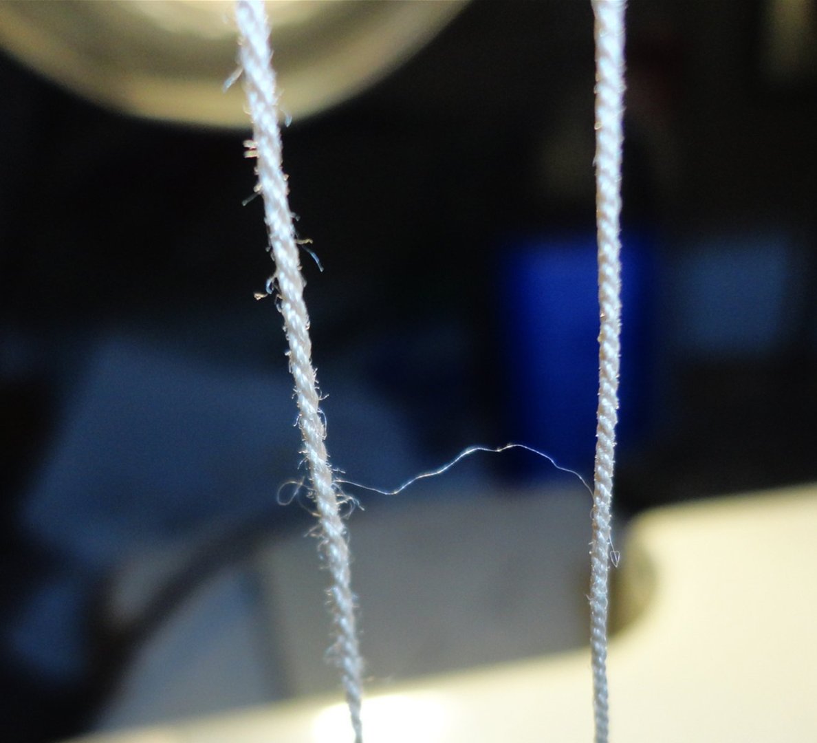
-
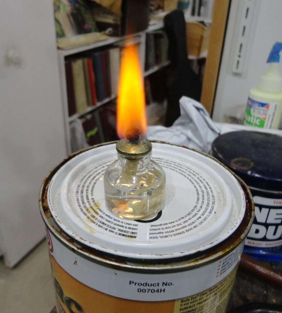
I'm using the Syren Rope Rocket (assy. reqd.) using Metrosine poly sewing thread: 3 single strands yield .010 scale rope (1" for 1:100), 2 threads per strands yield .020 (2" rope at 1:100) and 3 threads per strand yield .030. Ploy rope is tempered for 7 min. on a cookie sheet in a 350 degree oven, then it won't self-ravel. There are some 'fuzzies' (as some of your photos show), and I found they can be singed-off by quickly passing lengths of the scale rope over an alcohol flame. Pausing over the flame will part the rope, so deftness is needed. The photo below shows fuzzy rope on the left, and singed rope (now mostly smooth) on the right. Close-up photos tend to show more of the 'fuzzys', so why not get rid of them. Will likely work on natural fibers as well.

-
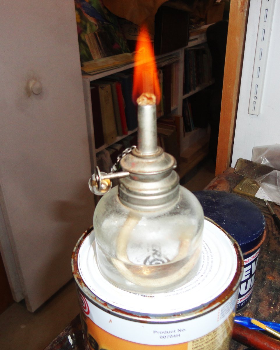
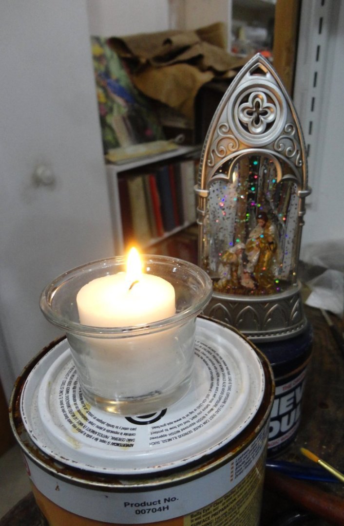
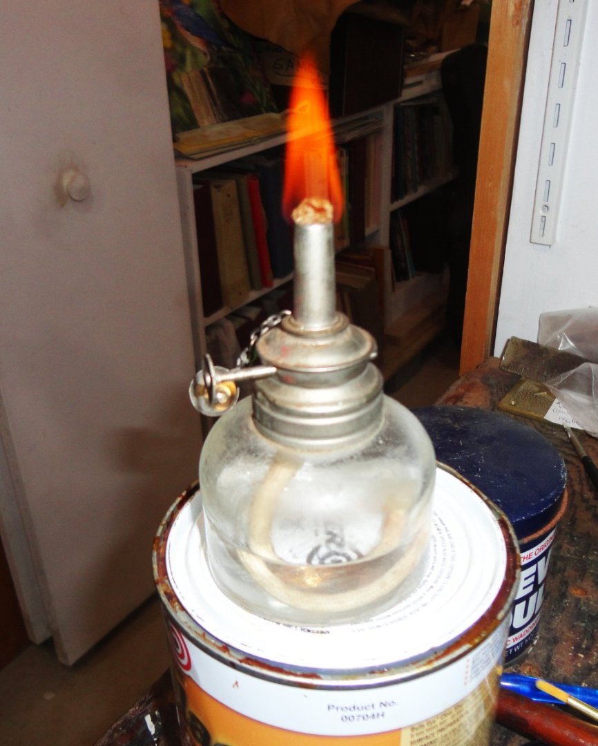
A couple clarifications on scale rope making ... I forgot that the clockwise rotation of the central gear makes the pinions go counter clockwise. Fortunately, most thread is left-hand spun, so counter clockwise rotation increases twist whether one, two, three threads are attached to each pinion hook. On the other end, the clockwise rotation distributes the over twist as the rope is laid - so if the rotations are balanced, the scale rope will 'fall off' when cut free without any kinking. With full size rope making, one can easily count the revolutions made on either end, or let the ropemakers' "top" self-adjust as it lays the rope. If one has a case where right-hand thread is used, then the drill direction needs to be reversed - something I've not run into yet. After baking (and it can be noticed also before) looking at the poly rope against backlight (or with any magnification to speak of) I definitely notice what I consider to be 'too much' fuzz on the rope - not as much as some kit rope, but too much. 'Guess this is why close-up photos are not the friend of the ship modeler, since every defect gets magnified - whereas just looking at a model on the shelf or in a case minimizes irregularities. I'll try and see if there are other thread sources (like linen), but until then I thought I'd try something I've done on 1/2" demo rope that looked too fuzzy - singe-off the fuzz. With full size rope this is easy. BTW, running the twine over beeswax before making rope also helps - guess that's why some modelers run rigging rope over some beeswax. After singeing large rope, there is still a little 'stubble'. So first I lit a propane torch set on low to run a length of rope (using both hands) over ... but it burns too hot and incinerated the poly rope immediately. That rules out anything hotter like oxy-acetylene ... 😉 I found a very small alcohol burner and used some denatured alcohol (pictured below) ... I still had to be quick or the flame would part the rope, but with deft hands (and perhaps a daft brain) IT WORKED ! The rope looks fine close-up. This little burner still produced too large a flame, but a swift passing, length by length, of the rope on a hank took off all the fuzz - and there were little 'sparks' as they singed as the rope passed along the flame. OK, I needed a smaller flame, so I found a votive light I got as a Christmas present (along with a Nativity Scene in miniature). This was set-up (with a small prayer), and I found the smaller flame harder to keep the rope on track, and it was hotter - but it worked. Then I came across my father's old alcohol lamp that is far better at controlling a moderate flame - this was the best solution. Since both hands are needed for singeing fuzz off scale rope, there are no pictures of me doing this - and I didn't want to bother the Admiral to video the process since there might be a dim view of an open flame so near all sorts of flammables. The final iteration will be try a less energetic source of fuel - perhaps 90% isopropanol from the local drug store.
-
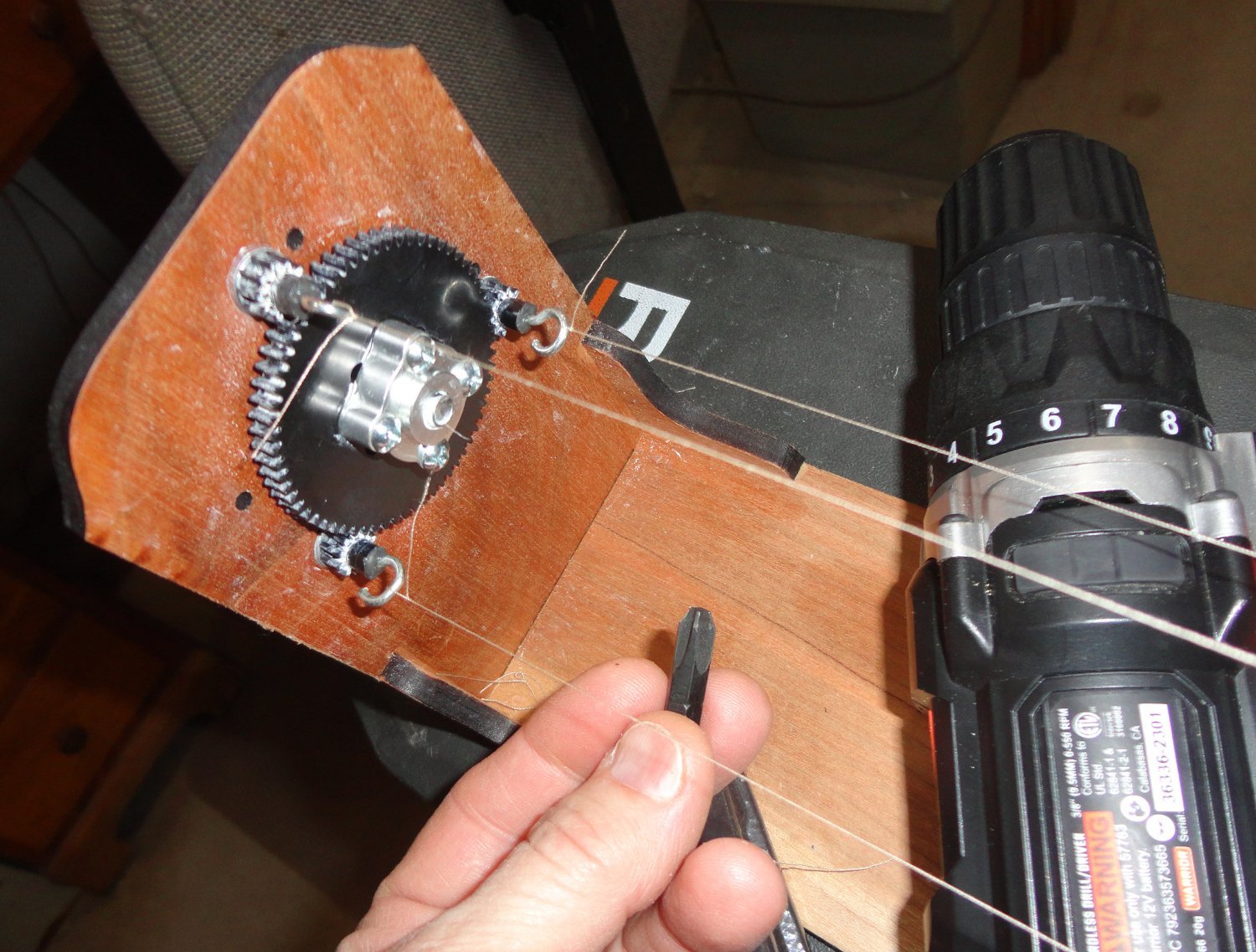
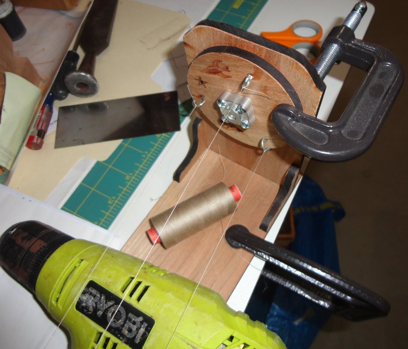
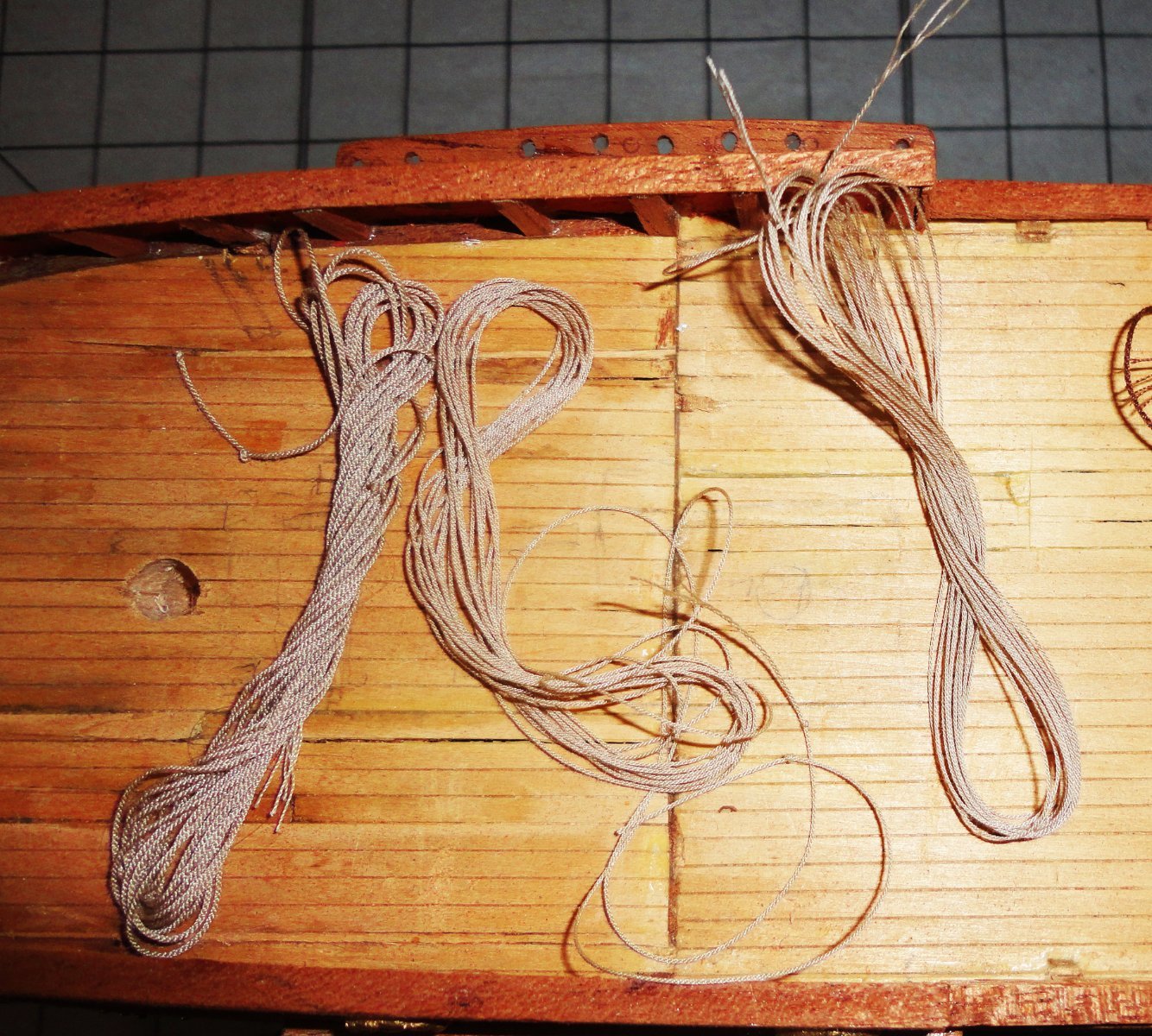
Having run hat orders for officer promotions in the re-enactment world, I started running some scale rope for the GF in tan Guterman polyester thread. Using a single strand in each of the three spinning points produces scale rope measuring around .010 in diameter ... that's 1" rope for 1:100 scale. Using two threads yields .020 - 2" scale rope, and 3 threads per yields .030 (or thereabouts) for 3" scale rope. I'll use thick rope in black for the shrouds and stays, medium tan rope for halyards, sheets and braces. and thin rope for most everything else. There are videos on MSW and via the Syren website, and once one has built the Rope Rocket and made a couple hanks - its pretty easy to make rope in whatever color and thickness you need whenever you need ... in the long run, an economical and practical way to go. I don't know how many builds I've seen where construction is nicely done, but 'kit rope' is used for the rigging that a.) doesn't look as nice as scale rope and b.) is way too 'hairy' or 'fuzzy'. Picture #1 shows the geared end (the white residue being lithium grease on the gears), and a 'stubby' Phillips head fits the coarse Phillips drive screw on the back side. I'm using a battery powered drill that has a 'lower' max speed, since there is something like a 3:1 speed-up from the large central gear to the three planetary gears with the spinning hooks. Thin rope is need now to pre-rig certain places on the GF, so only single threads have been tied. Chuck shows a setup with both ends on the same height table, but I clamped the geared end to an adjustable height stand - the kind used on either side of a table saw to support long boards being cut width-wise. Rather than loosen the clamp and moving it toward the other end with a free hand as Chuck does, I use my feet to nudge the stand - its only about a foot. The trick is not to spin the strands in step one more than you have to. Picture #2 shows the other end of the rope walk - in my case a mere 10 feet long - but could extend it another 6 feet if I wanted. If the weather was clement (meaning warmer), I could set up in an open garage with a 40 foot walk going out the open garage and down the driveway. But I've 'cut my teeth' doing 9 foot hanks, and there is a certain 'feel' to the tension and how far you have to move each end in the 2-step process. Also, making a 30 - 40 foot hank takes a lot more spinning time, and you have to hold whatever drill(s) you are using the whole time. Note that there are 2 clamps holding the 2nd end for the 2nd phase of rope making - and I'm using a high speed corded drill (about 2 1/2 faster than the battery drill), since the 2nd end does not have any gearing and the slower drill would take 3 times as long to do step 2. As the 2nd end is spun, since it faces the other way relative to the 1st end - one still uses the drill running clockwise, and the rope is counter spun relative to what was done on the 1st end. The rope winds itself from the center out. Real life rope walks work somewhat differently (self-twisting from the far end using a juggernaut once the tension on the three strands accumulates), and I've tried to devise a miniature rope makers 'top' to do the whole job in one operation - but the difference in scale makes the rig behave rather differently in relative tension than full-sized rope making I've done at demos. When running the 2nd end on a table top, the free hand (after clamps are removed) lets the 2nd end 'float' as the tension varies - and it actually lengthens before getting shorter - go figure. There is a bit of 'art' to this process, so someone new to it has to practice a little to get the hang of it. Heres a picture looking down the rig after I cut-off the rope just made. The Rope Rocket works like a charm. After the rope is made, it should be 'stretched out'. If a bit over spun, there will be some kinking - which is just shook off, and the rope will adjust itself. Using polyester thread, one heats an over to 350 degrees F, puts the rope made on a cookie tray and bakes for 7 -10 minutes. This 'sets' the poly and the ends won't unravel unless you manually do so (for whatever reason). Some use cotton thread - and I suppose laid rope like this will be less likely to break over time, as my Dads ship model had mere sewing thread that did start breaking after 50 years or so. Obviously linen would be best, but it is difficult to find suitable linen thread these days. Hemp is an alternative (if decent thread is found). Chuck says to wet the rope slightly before cutting off and stretching is cotton or other natural fiber is used. Poly does not need this, and natural fibers don't need baking - go figure. Below are three hanks of tan rope, with .020 on the left and the other two .010 - looks good to me.


-
As for rolling small hammocks, using a fine 'natural' linen (off white) might work well. There are also 'linen look' cottons, but they tend to haver thicker threads. At scale, the material would look nearly smooth.
-
I'll agree that most 'aluminum' you can easily find is 'gummy' and does not machine that well. Yet once upon a time I worked for a company that made aircraft controls and components, and I was able to collect samples of 'bar ends' of decent-machining aluminum alloys. One prized piece was referred to as "hard aluminum", and it took effort to scratch it - yet it cut beautifully on a lathe. I've rationed out my available stock over the years doing small projects.
-
Many say the brads are to hold the first planking until the glue cures. Some pull them out after that, while some just sand over them. Your first planking looks pretty good, and sanding should suffice. Yet I've seen some who slather filler all over everything and then sand away. 'Guess its whatever works for you. I don't mind working with thin stock, because its easier to soak in warm water and should bend easily. Since the bottom gets coppered over (and there are many ways to do that), I'd focus on how the planking that shows looks and not worry too much about the second planking that gets covered over.
-
With the right wood, small tools and a steady hand, much is possible.
-
'Love the backdrop ... ever watch Bob Ross paint on TV?
-
Ahoy Beth, A problem with copper is that over time, humidity in the air can cause green colored compounds to form on the metal - and that can stain the cloth. Obviously, you don't want to use thin steel wire, since that can spontaneously rust and also stain the sail cloth. The best idea is to use brass wire, which almost always (over time) will get a simple brown patina. If you use jewelers brass wire (used by bead crafters and found in many craft stores nationwide), the wire comes clear coated to resist even getting a patina - so will stay brass colored for a long time. Since the thin wire is run through the fold-over of the sail edges, you should not be able to see that there is wire inside. It can be flexed as desired to get the sail shape you want.
-
Rather than 'paint' - and most consider paint to be thick enough to 'cover' (ergo hide) the wood below - why not experiment on some stock with a 'tint'. That could be white paint thinned enough so that it becomes a 'wash' - with the carrier soaking into the wood (it will out-gas as it dries) - leaving behind 'transparent' pigments on the surface. This is more like staining, and there might even be white stains. Experimenting on samples of the stock you are going to use is key (you don't need much), and you can use both sides of the same test piece to experiment on ... just label each side with a number or letter and keep a key as to how you treated that sample.
-
Lots going on in life means delays in the ship yard. Part of the process is 'learning the ropes' - and I mean well enough to visualize them on the ship for the purpose they're intended for and how they are routed from end to end. I keep imagining how I'd go aloft to manage the sails, and how on the deck the lines would be utilized and belayed to the right place every time. Finding glitches this way means repeatedly going over the drawings and making changes as needed - since I'm making my own plans. Now I can 'get' the frustrations sometimes expressed by those new to sailing ship modeling ... that no one can 'just tell them' what they need to know. One has to LEARN this for the project at hand, and the rigging changes greatly for each time period and type of ship in the age of sail. Those with the benefit of 'plans' often find simplifications and other glitches there depending on how far one wants to go 'into the weeds'. Real learning is done by the individual, and that takes a variety of sources and (thankfully) the large array of builds (complete or not) to be found on MSW. Another part of the planning is figuring how everything has to go on a small replica. Some of the belaying pins in 'tight' areas need to have lines pre-attached, coiled (with wire for twist ties) and laid over the gunwale for later use. I'm going to try using the Airfix loom or similar layout on a board (with modified technique posted elsewhere) for the shrouds and ratlines, fixing the top (narrow) ends to the tops/crosstrees (given the existing mast assemblies that I have to work with already), placing the bottom turnbuckles for the next level with their futtock shrouds passing through the shroud set below, then rolling the shroud set from the bottom up and tied for later utilization. The bottom ends will be attached and tensioned to the turnbuckles below much later in the rigging process, and the loose, pre-sewn ratlines adjusted and fixed last. Forestays and staysails will have to go in early after the masts have had the yards with sails (with much of their associated lines) assembled off-model before planting on the deck and belaying line ends. Those pre-coiled lines will come up to where they need to go. Braces can be done from either side. Obviously, lilliputian ship modelers (the same size as scale crew figures) would have no trouble running lines in the order done for actual ship construction ... but I have to deal with fingers much larger (and far less nimble) that scale crew. There are still a lot of things to go on the deck - various pieces of equipment and the railings (there's a task ... putting all the uprights for a run of railing on triple wires, then bending and fitting so the stanchions get in place without the railings kinking too much). I'll have to bodge things as best I can, then take some pictures when there's something to show.
-
Don't I know this ... a blue pill might help 😉
-
Returning after a long absence
Snug Harbor Johnny replied to mrjuan's topic in New member Introductions
You'll find this forum a smorgasbord of modeling and nautical information, -
The issue comes under the protection provided to forums (such as ours) for what a rogue individual might post. Efforts continue (via SCOTUS) to undermine this long-standing precedent (as efforts to continue to try and 'flip' any Supreme Court ruling when the makeup of the Court changes, regardless of how long a prior ruling has been in effect) face considerable headwind in Congress, as seems to be no agreement how a 'halfway' measure could be fabricated - or how said wording might be interpreted by any court. Bottom line, anyone can sue anybody for anything (if they have enough money to burn). WHAT IS SECTION 230? If a news site falsely calls you a swindler, you can sue the publisher for libel. But if someone posts that on Facebook, you can’t sue the company — just the person who posted it. That’s thanks to Section 230 of the 1996 Communications Decency Act, which states that “no provider or user of an interactive computer service shall be treated as the publisher or speaker of any information provided by another information content provider.” That legal phrase shields companies that can host trillions of messages from being sued into oblivion by anyone who feels wronged by something someone else has posted — whether their complaint is legitimate or not. Politicians on both sides of the aisle have argued, for different reasons, that Twitter, Facebook and other social media platforms have abused that protection and should lose their immunity — or at least have to earn it by satisfying requirements set by the government. Section 230 also allows social platforms to moderate their services by removing posts that, for instance, are obscene or violate the services’ own standards, so long as they are acting in “good faith.” WHERE DID SECTION 230 COME FROM? The measure’s history dates back to the 1950s, when bookstore owners were being held liable for selling books containing “obscenity,” which is not protected by the First Amendment. One case eventually made it to the Supreme Court, which held that it created a “chilling effect” to hold someone liable for someone else’s content.
-
Once enough salvage and research has been done on the 16th century Mars wreck, it might be cool if there were a kit of THAT ship.
-
'Saw the shroud loom video and have a couple observations ... 1.) The demonstrator used the same thin cotton thread for both the shrouds and the ratlines. I suppose a better effect might be had by using thicker line for the shrouds - preferably spun line using a Syren Rope Rocket or the equivalent (or just purchased). 2.) A white card with horizontal lines (on both sides) corresponding to the ratline notches on the loom being used could be affixed as convenient in the middle of the loom. Then, 3.) Instead of wrapping thinner ratlines around the perimeter, one would use the "sewing" technique to run the ratlines (one at a time) horizontally with a long, thin needle through the thicker shrouds - using the lined card underneath as a guide. This technique has been used on a few MSW builds, so one has to look for them. The ratlines don't have to be 'tensioned' but can have a little 'sag' between shrouds as is commonly seen in photos of old sailing ships. 4.) After sewing all the ratlines on a side (leaving plenty of loose line on either side), adjust the shrouds as needed. 5.) A very small amount of CA or thinned PVC (as many prefer) can be applied to the joints (except at the first and last shrouds) with a tooth pick to 'lock' those places. 6.) The ratlines for the first and last shroud are tied with a Cow Hitch. This makes the end of the line run INWARD toward the run of the ratline, instead of outward if a Clove Hitch is used. Then bit of line left over when trimmed will not 'stick out' from the end shrouds, but be concealed by the run of the ratline. The bottom ends of the shrouds can be tied either to the 'fake' deadeye pairs (appearing to be laced already) provided by the kits - which is not that bad for the 1:144 or smaller scale plastic models, as to try and used actual deadeyes at that scale can be very difficult and frustrating for most modelers. (Of course, some have done it regardless.) The narrow upper end gets glued as innocuously as practical. For the larger 1:72 kits, one could strop the lower end of each shroud to a deadeye, fix the position of the narrow top end of the shroud set, then lace the deadeyes at the bottom of the shrouds to the pre-mounted lower deadeyes (tensioning as needed). This could still look OK and be a lot easier than truing to do all the ratlines on the model.
-
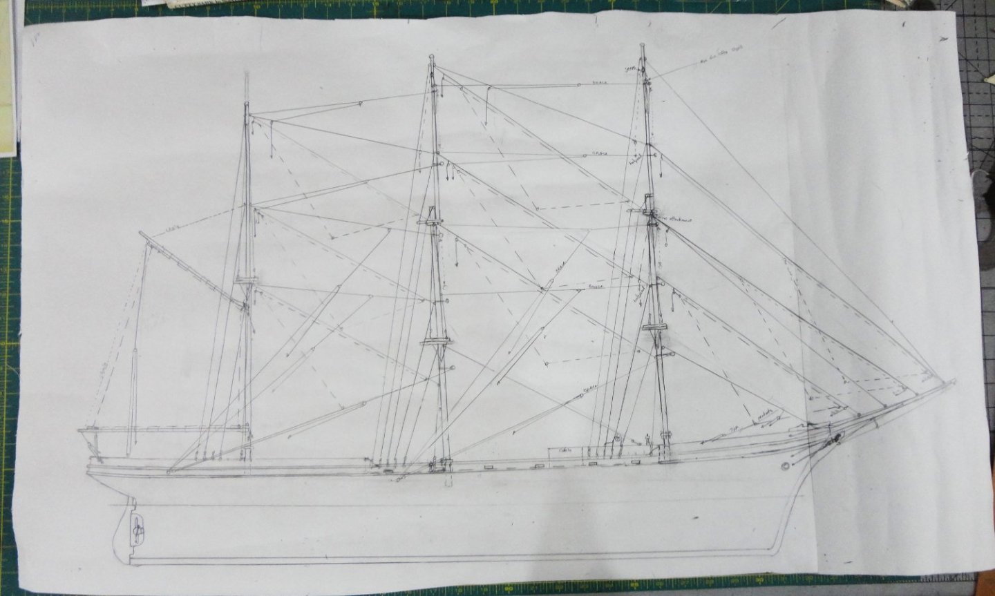
'Thought I'd make a full size drawing to be sure of how the rigging might look. Since the masts, as built, have their own peculiarities (inaccuracies) - I have to use them as-is for restoration purposes, and adapt reasonable compromises per belay points, etc. This has been a cool exercise, since 'winging it' would have been a mistake - that is, the mistakes would have been made on the model. Then the corrective measures would have been tedious in terms of non value-added activities (including hair pulling). So I made many erasures on the paper (nice new-world discovery, the rubber eraser is), editions and notes ... and the present iteration is pictured below. There is a nice look to her - she's definitely yar. In the process of drafting, I realized I'd mis-place the forward boomkin ... too far forward. Now the advantage of a solid hull comes into play, since I only had to drill new holes on either side to place the parts in. Then a plug of the same stock was cut, some wood glue applied, then it was tapped into the old hole flush with the surface. A couple dabs of paint will blend-in just fine. Speaking of solid hulls, I'd watched a Scientific kit (supposed to be 1:96, but might be a tad smaller at 1:108) of the Thermopylae (supposedly their 'best' clipper kit) on Ebay that had originally been $140, then reduced to $99 - since some work was already done on the hull (hardly started). Not forgetting a fascination with that ship's lore and that the GF is a 'dry run' being barque rigged as the Thermie was in the timber trade, I ordered it since there were no more reductions and the other two examples of the same kit had disappeared. They do come up every now and then.
-
"Much of the satisfying work of life begins as an experiment, and no experiment is ever quite a failure." Alice Walker 1944 - ...
-
This is a super project, and one I'll follow.
-
With baited breath, the cat breathed into the mouse hole ... You might say it was a better mouth trap. 😉
-
Tool Rest Question
Snug Harbor Johnny replied to kgstakes's topic in Modeling tools and Workshop Equipment
Try and see if someone with a little lathe know-how can fix your fine machine. Perhaps there are machinists forums that might lead you to a local resource. Failing that, a logical examination of the problem might guide you to You Tube videos that can help you proceed. Heck, I needed to replace garage door springs, and found what I needed to know on the Internet. Same goes for a variety of mechanical challenges. Then again, being handy helps a lot too. Daniel Boone is quoted, "First, be sure you're right. Then go ahead." -
A masterpiece ! ... a fine example of true "Museum Quality". I think she'd be a fine acquisition for a Nautical Museum. I'll pick my jaw off the floor and only dream of emulating your skill and craftsmanship.
-
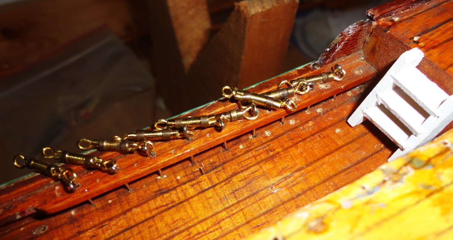
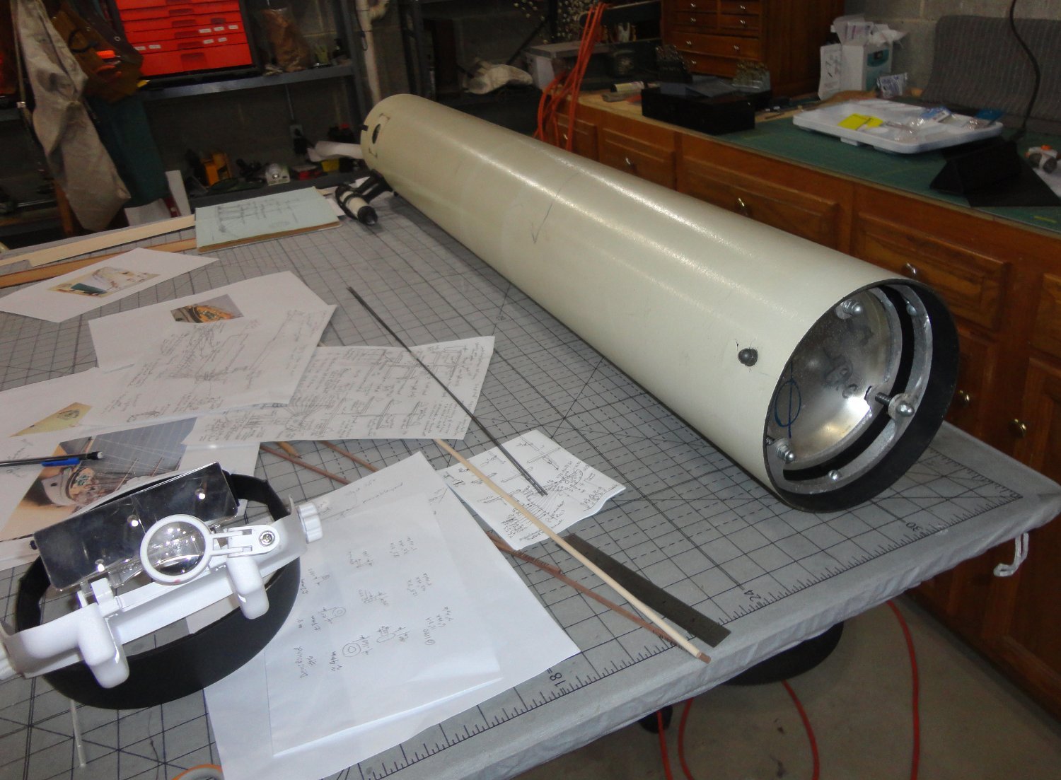
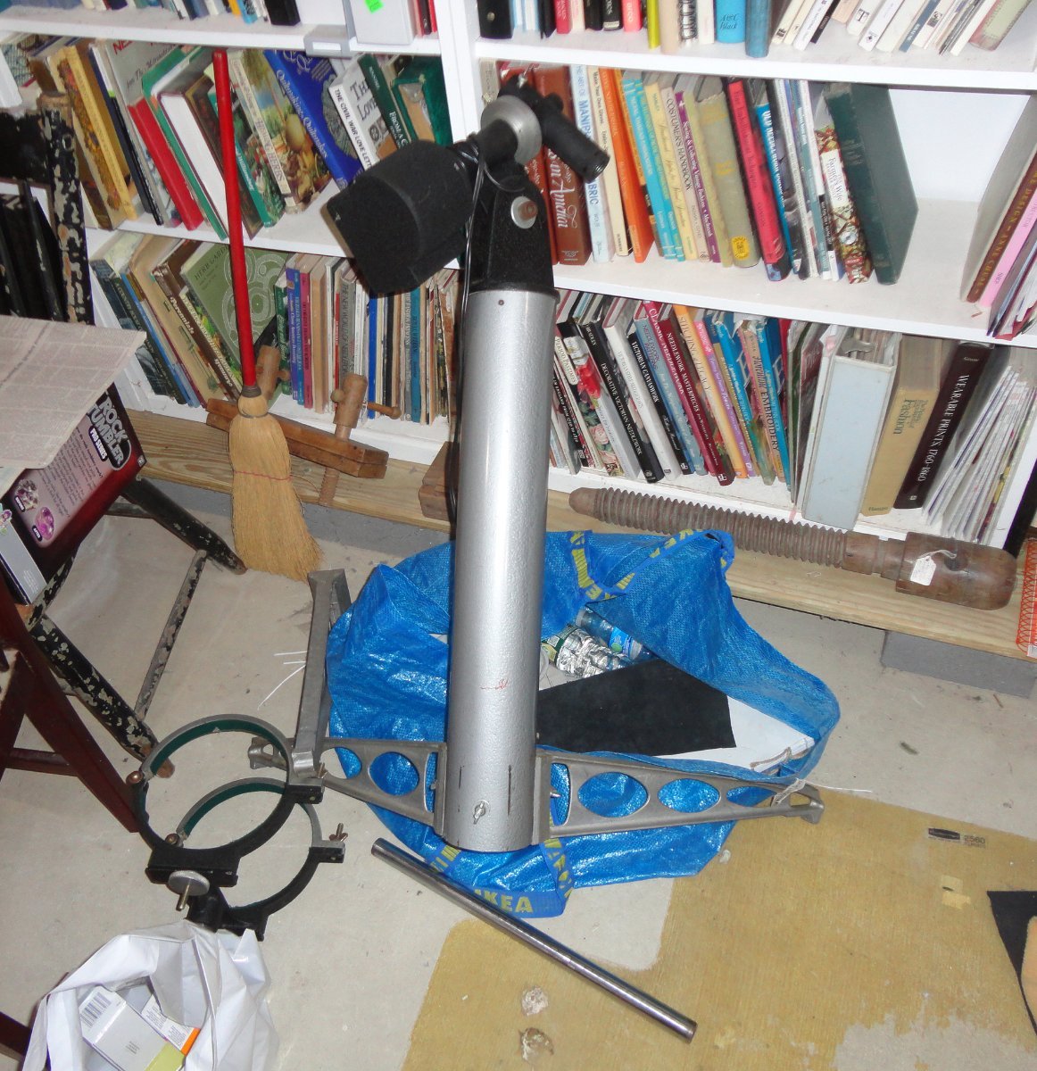
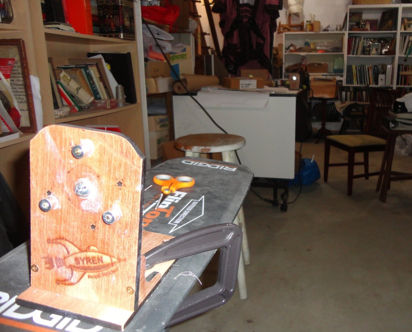
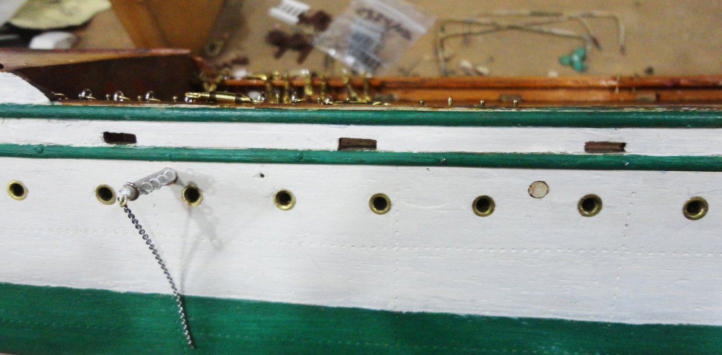
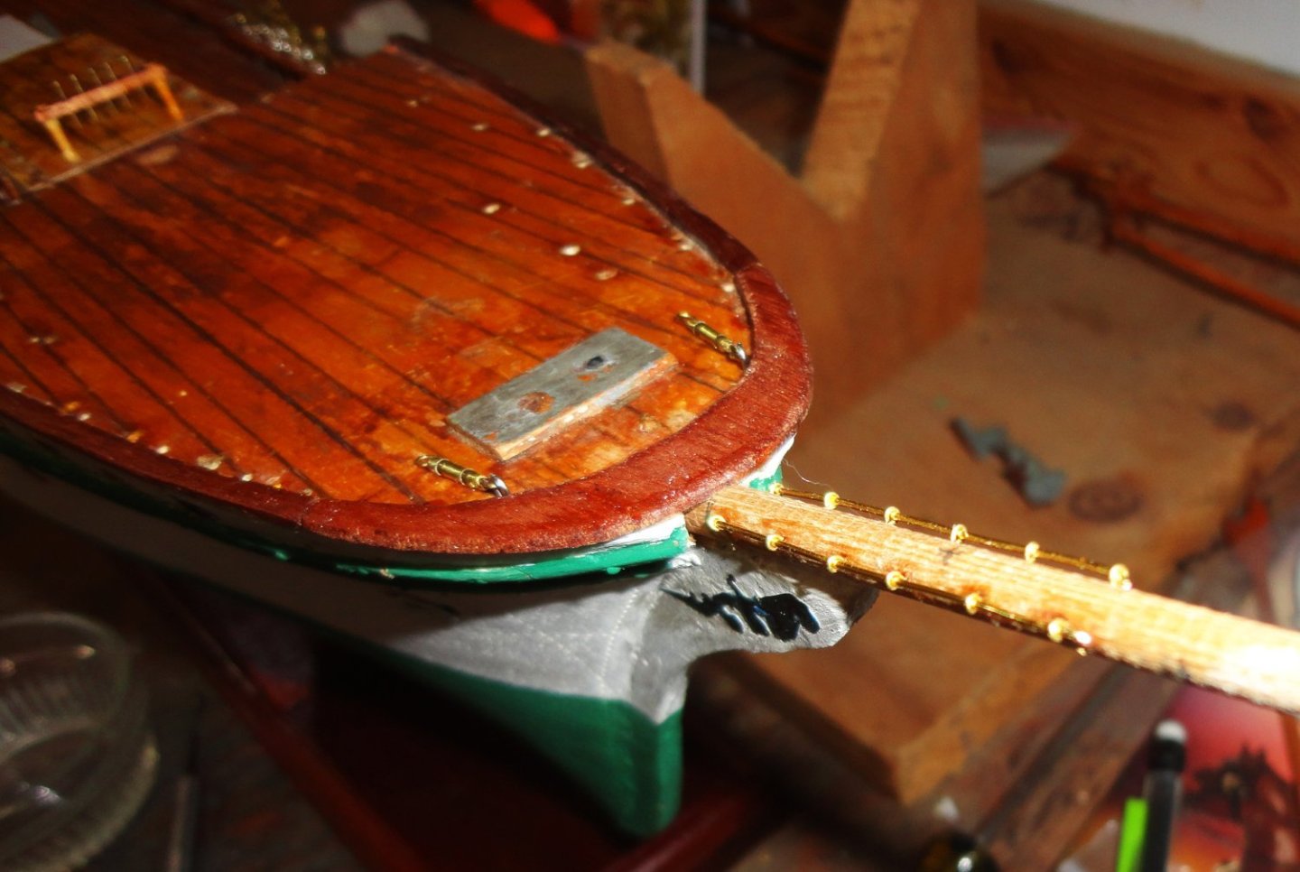
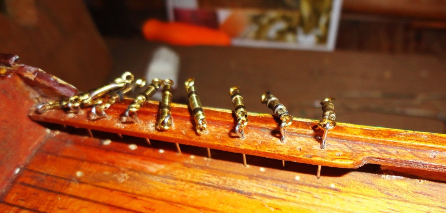
'Have done a couple things on the GF - I'll have to finalize what's done on the bowsprit at some time, so started with what appear to be jackstays on either side for a certain distance. My guess is that they might offer some foot purchase until a cadet could get a hands on the stay cables. There will be a long cable on either side going from the point of the bowsprit to the hull, and the ship has netting suspended from these cables going entirely under the bowsprit as a safety net - a wise precaution. Drilling for eyes and threading 22w gauge brass wire through before gluing is good practice for the jackstays that will go on all the yards. Note that a pair of small turnbuckles are fixed by eyes on the fore deck, that will be for the 'split' lower forestay. The breaker shield (already built) has yet to be glued. The larger turnbuckles are mounted in tow places (so far) on the port side. 'Found I had to bend hardened quilters pins into eyes, and the ends were forced into the hull as the original builder did. The soft eyes (ship findings) kept bending when I tried to force them in - so harder pins were resorted to - just that the eyes are irregular, but trying completely round tapered needle nosed pliers makes for better eyes ... I have no intention on pulling these out, as I prefer to go FORWARD (not back) - unless absolutely necessary. Small holes were drilled for belaying pins (not installed yet), and the drill bit did mark the deck below (my bad) ... a touch of shellac will blend those marks. I think I'll have to pre-attach line to at least some of the belaying pins, since there will be 'tight spots' in certain areas - like when the stairs so in with railings. 'Lots of though still on which order to do stuff in. As usual, the ship yard is by no means my only interest. And lately I thought it would be nice to look for a used telescope to at least look at the moon as the phases change - lots of shadows and craters seen clearly wherever the 'terminator' (lunar day-night zone), plus whatever planets might be available. And I found one locally - an old Criterion RV6 - 6" f8 Newtonian on a motorized German Equitorial mount. The scope itself was only $375 (assembly and tweaking required - like modifying a spare pinion to fix the focuser). Another $125 bough some decent eyepieces and a Barlow. The optical tube is lying on my wheeled project table. 'Still some additional assembly needed for the mount pictured below.


-
Tool Rest Question
Snug Harbor Johnny replied to kgstakes's topic in Modeling tools and Workshop Equipment
Wood and metal turning ... two different animals, and I wouldn't advise trying to do both materials on one lathe type. I used to have a Sears wood lathe, and turned furniture parts on it. There were bolt holes in my home made bench top so I could take it down after one project was done, and it fit on a shelf underneath. The "bench" was actually the extensions built 6 feet on either side of my Craftsman 10" radial arm saw, and I used either side as a 'standing-up' height work bench. Sold the lathe and saw when I sold off my wood stock due to forced relocation ... but I kept the bench wings, and they were 'married' into a long bench now in my man cave in our present digs.