Snug Harbor Johnny
-
Posts
1,500 -
Joined
-
Last visited
Content Type
Profiles
Forums
Gallery
Events
Everything posted by Snug Harbor Johnny
-
 Stunning and inspiring ... and very instructive for those who would follow with either Bluenose or Bluenose II !
- 282 replies
-
- 1
-

-
- Bluenose
- Model Shipways
- (and 1 more)
-
An interesting challenge ... best of luck !
-
215' x 12 (inches per foot) = 2580" full scale hull (O.A.L. as opposed to 'between perpendiculars' ... a different bugaboo). 2580 divided by 32 (your hull) = 80.625 ... call it 1:80. You may be better off with a slightly larger model to work on. EDIT: - additional info. 'Seems the T (according to a public source) was 212' "between perpendiculars" (Wikipedia states the CS as 212 1/2' registered length, implying between perpendiculars) Three other sources note these same distances as being between perpendiculars. ... This is an interesting point, sometimes misunderstood (as I had done before). The "perpendiculars" (used as a standard concept of registered vessel length) consist of a vertical line where the cutwater at the bow meets the waterline (not sure whether this is laden or unladen, as it would make a difference depending on the angle of the cutwater), and another vertical line that is the centerline of the steering post. The distance between these vertical lines ("perpendiculars" meaning 90 degrees to the waterline) is measured. I took out the Revell 1:96 T hull half and measured about 25 1/2" along the point where the exposed planking meets the molded copper plates from the cutwater to the sternpost. Hmmmm, if multiplied by 96, I get 2448", which is only 204'. So something is wrong. If I multiply the 25 1/2 inches by 100, I get 2550" full size. Divide by 12 to get ... 212.5' (the model hull was made for CS), or about 1:100 scale between perpendiculars. Now if the kit designers (Revell CS & T) were using the "length on deck" (stern to the forecastle point, which does not include the bowsprit, which if added to the length on deck would give the O.A.L.) to figure the model scale, 212.5 x 12 = 2550, divided by 96 = 26.56". So I measure their model hull's 'on deck' dimension to about (here it comes) ... 26 1/2 inches ! This is an "Ah-ha" moment. The Revell kits are 1:96 if the registered length is taken for an "on deck" measurement. Ok, one can quibble or niggle over the difference between 1:96 and 1:100 ... I actually use 1:100, since its easy to do the math for fittings: e.g. an 8" block (about 200mm) is 2mm at 1:00 - and blocks most often come in millimeter sizes. Working with 2mm blocks is a pain, and many modelers get go a bit oversize here and there so a 3mm block can 'pass' for an 8" block on a 1:100 model. I digress ... IF Simon's model is about 32" stern to the knight head (more or less the 'on deck' measurement), so deduct 1/2" to be safe to get 31.5", and the difference between on deck and between perpendiculars is about 96% (25.5 divided by 26.5 = .962), then the between perpendicular value on his model should be about 30 1/4" (30.72). The full size is 212' x 12 = 2544", then divide by 30.25 to get ... drumroll ... 84.1 So my guess of the model scale is about 1:84, which is still a good scale.
-
Ahoy Tom, I like your method, in that dealing with brass wire railing (especially if there are two or three levels of railing) can be a real pain ... as seen in some other builds. There are problems with kinking, etc. that I wondered about. Certainly with any straight run, (especially in relatively small scale - my project is at 1:100) the thread can be tensioned as desired before 'setting' the entire length with CA - then it can be painted. OK, so what about railings that are bent around a curve for the stern? (That is, if one does not want to have straight segments going around - which is not all that bad in itself.) A curved block of balsa can be made (with slight grooves that the stanchions will fit into) as a 'form', and if covered with waxed paper glued to the form (with a VERY thin topping of petroleum jelly) the rope (thread) railings won't stick to the form when CA is applied. They will cure and remain curved when the form is removed. Note that there the curve is still 'set' in sections to permit the form(s) to be removed - since trying to do the whole thing at once might 'lock' the form inside the horseshoe shaped run.
-
You provide a step-by-step 'instruction manual' on your excellent resurrection of the Mary Rose. One that helps me with ideas on my presently suspended Great Harry build. Of note is that there are heavier strakes at intervals going up the stern castle (reinforcement, no doubt) with lapped clapboards in between. There appears to be a 'gallery' level where a row of lunettes (or other shaped portals from which weapons would be fired) are to be placed. This band could be planked differently than the lapstrake clapboards above and below. These 'bands' of planking between reinforcing rails makes the 'layer cake' decorations seen on the Anthony Roll (and elsewhere) make sense. The top deck level allows for spaced shields. Your build log is a wonder o behold. Fair sailing, Johnny
-
Actually, Spock was paraphrasing a Sherlock Holmes quote written by Sir Arthur Conan Doyle. Of course Spock said, "Logic is little bird tweeting in meadow. Logic is a bunch of pretty flowers - that smell bad."
-
You've done a SUPER job on the Beagle with keen attention to detail and execution - KUDOS. I like how the deck planking turned out, and reviewed your build from the beginning to see the process how you dealt with the trouble many have with pencil graphite getting the deck dirty. Perhaps the varnish 'sealed' loose graphite, so it cleaned up after scraping. I also saw how you later scraped off the deck some more to remove the dark 'dots' at the butt joints - with further improvement in appearance. (Holystoning with glass !) I may experiment with applying graphite to planking edges and then just sealing the edges sparingly with varnish applied with a mini swab often used for fine paint details. That might pre-seal the edge before planking and prevent graphite getting on the surface in the first place ... but this is only in the 'idea' stage and untried. We know that trying to 'paint' plank edges with anything risks 'bleeding' into the plank itself - something that can't be fixed. Some have used the black thread between each plank method - again, something I have not done yet. But your method of glass scraping is way cool. 'Also looked at your coppering process - and there are many methods shown in the forum. Yours did well on the Beagle.
-
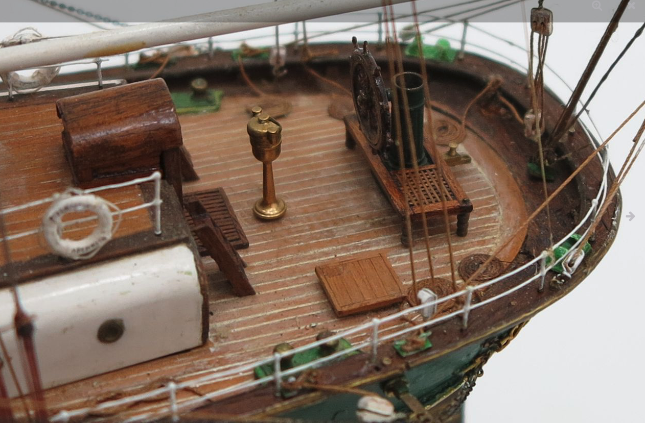
I've seen photos of the antique model before, and questioned a number of details that don't seem right for the 'Big T' ... yup; the completely walled in forecastle with no windless is definitely not typical, there is an aft cargo hatch (that is, an opening for a hatch - the model is mostly not decked) where there is none on the Hume model (or line drawings - plans that are available) where there should be a capstan, the entries (companionways) have flat tops (instead of bowed to either side) on the rear cabin are 'offset' from each other (rather than be on the centerline) ... ... there is something that looks like a chicken coop ( a-la the one on the C.S.) behind the forward cabin as well as some other structure in front of the main cargo hatch, There are slight channel extensions to the gunwale for the deadeyes (which are not on the Hume model ... and the entire gunwale may have been a little wider than average, so any rubbing against anything would not affect the deadeyes) - and they are 'mirrored' by mini-channels below them where the chainplates pass through, which are not on the Hume model. Note also the nice angle of the stern right up to the gunwale. ... there should be some bulwark around the poop deck (what, 'knee high' or a little less, and you can see big differences what is on deck.
-
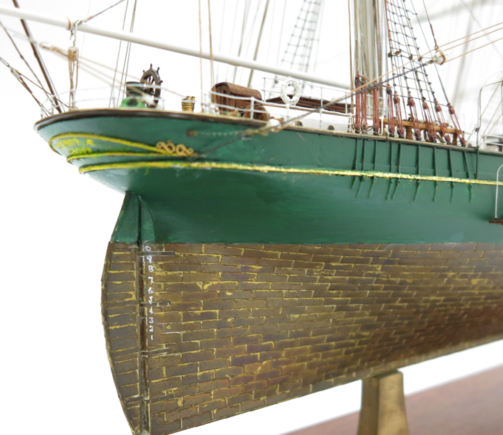
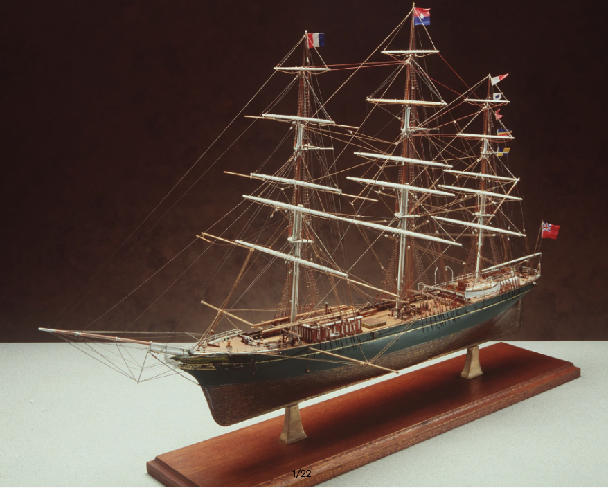
There are a couple of things I've wondered about regarding Thermopylae - these relate to the model by Hulme (some text pasted below) This magnificent model of the famous tea and wool clipper "Thermopylae" was made by one of Australia's most important maritime historians, authors, ship modellers, and experts on clippers, Cyril Hume (1900-1984). Clippers were extremely fast sailing ships of the 19th built to carry expensive perishable cargo quickly around the world. They were low in the water and carried enormous amounts of sail. The term clipper, coined in 1830, was used because such ships clipped or moved swiftly. Cyril Hume first became interested in clippers when he was unemployed in Sydney during the Great Depression. He began ship modeling as a hobby to occupy his enforced leisure hours, but it quickly developed in to a lifelong pursuit. He combined to an exceptional degree, the technical skill of a craftsman and the historical accuracy of a scholar. Even in the late 1930s he sought out former sailors from the actual "Thermopylae" to ensure all the details were meticulously correct and true to scale. The rigging on his model is so painstakingly accurate in scale that a single strand of human hair was used for the signal halliards. Tiny water barrels on deck have individually-coopered staves and one of the blocks, which is less than 1/16th of an inch in length, has a working sheave. Cyril Hume became a world authority on the clipper ship era and gained international acclaim. "Thermopylae" took some 8,000 hours to complete and is believed to represent the crowning achievement of his model making career. There are many images of this model available, and I note that the anchor chains drape on the deck very far astern before going below deck. Of course there is a capstan located aft of the main mast that may have taken up the chain. I've not seen this sort of arrangement on any other clipper thus far, and wondered what your opinion was. I also note there is no cargo hatch aft of the main mast, in agreement with deck plans from other sources. The shape of the companionway covers on the aft cabin differ from what is seen on other models. So the question is, should the Hulme model be considered 'definitive' on Thermopylae? With respect, Johnny Edit: This makes the prospect of busting (somewhat) the Revell 1:96 version even more daunting. 'Very difficult to extend the aft deck the way it should be while trying to use the HIS Model wood deck overlay (I've never been able to paint plastic decking well enough to resemble wood the way the best practitioners have).
-
Being a Thermie Groupie, its wonderful to see how you are doing this scratch build. There are many photos of models that bristle with cannon, drip with ornate carvings and have a vast spider's web (or spaghetti bowl) of rigging - and they are wonderful to behold - yet I find great beauty in the clean lines of a well planked hull with enough additional detail above deck as needed to represent the original. Rather than be distracted by a display of modeling virtuosity I'm incapable of (but there's no harm in that, just as there is no harm in listening to a virtuoso rendition on a musical instrument ... a man can dream, can't he?) I find as much enjoyment from good basic modeling work, and there is much to find (and learn form) on MSW !
-
I'm still agog at how incredibly impressive your scratch build is going.
-
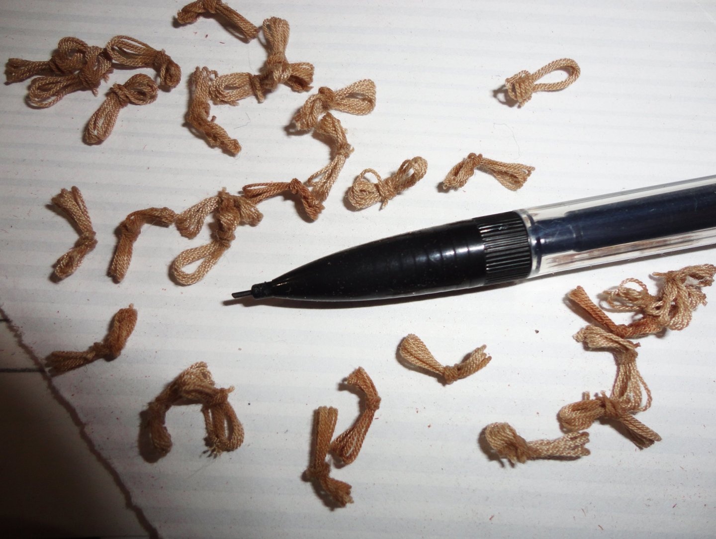
'Finally 'simplified' my procedure of hank making ... just four times around the pencil before tying - then three wraps (starting behind the coil) with the end of the third wrap passing through the loop of the second. The CA sets the shape they need to have to look right on the 1:100 brass belaying pins. The first few I'll replace with the new version so they'll appear about the same - even though each one is unique on close inspection, just as hanging coils tend to be. With tons of 'good weather' tasks to do, I'm doing very little in the shipyard ... 'have to make hay while the sun shines. Below are the first 30 made - with 120 more to go. I thought the U.S. Coast Guard Eagle looked like the Gorch Fock ... 'seems we got her as war reparation (after Googling a little to find this out) - I've pasted some info below on the 'Gorch Fock' class of training ships built in the 30s. The GF was designed and mostly complete before the Nazi take-over. Eagle commenced its existence in Nazi Germany as Horst Wessel, a ship of the Gorch Fock class. Horst Wessel was an improvement on the original design. She was larger in dimension and her spars were all steel, unlike Gorch Fock's wooden yards. SSS Horst Wessel began life as Schiff ("ship") 508 at Blohm & Voss in Hamburg, Germany in 1936.[4] Her keel was laid on 15 February, she was launched on 13 June, completed on 16 September, and commissioned on 17 September. She was the second ship in the class to be built, following the class namesake Gorch Fock. Rudolf Hess gave the speech at her launch in the presence of Adolf Hitler, and Horst Wessel's mother christened the new ship with a bottle of champagne.[5] The name was given in tribute to SA leader Horst Wessel, who had been accorded martyr status by the Nazi Party. He also wrote the song which came to be known as "Horst-Wessel-Lied", which was later used as the Nazi party's anthem (banned in Germany and Austria after the war). Shortly after work began on Horst Wessel, the Blohm & Voss shipyard laid the keel of the German battleship Bismarck, which was labeled Schiff 509.[6] SSS Horst Wessel served as the flagship of the Kriegsmarine sail training fleet, which consisted of Gorch Fock, Albert Leo Schlageter, and Horst Wessel. (Mircea was also built in 1937 for the Romanian Navy, and work began on a fifth ship called Herbert Norkus, but was stopped with the outbreak of war.) Note: The Albert Leo Schlageter now serves as the Portugese trainer Sagres. As the 3rd ship with this name in the Portugese Navy, she is sometimes referred to as the Sagres III. The Mircea was taken by the Russians for a while, then returned to Romania where she is still in service. The Russians also had the Gorch Fock, which eventually came back to Germany after they had built the Gorch Fock II .
-
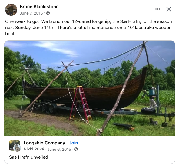
I know someone so 'into' this that he's run the 'Longship Company' since the 70s. Pictured below is the third (and best built) boat, presently located in southern Maryland on the Potomac estuary 9an offshoot of the Chesapeake Bay. 'Thought you's like to see it.
- 146 replies
-
- 5
-

-

-
- Roar Ege
- Billing Boats
- (and 2 more)
-
Thus far, I've never been the first to say "Welcome" to a new forum member ... but I'll say it anyway - Welcome!
-
You have a deft touch with the chisel (must be quite sharp) used thusly ... Hats off to your courage ! Said the cowardly Lion, "What makes a King out of a slave? - Courage. What makes the flag on the mast to wave? - Courage. ... What makes the Hottentots so hot? Who put the ape in apricot? What do they got that I ain't got? ... Courage. - You can say that again."
-
My apologies for not realizing we had different editions of the kit. I saw a build log (non-MSW) of a 2005 (1st edition) Roar Ege kit that had plastic ends for the ship's stand, among other differences. Since that time, there have bound to be tweaks and changes in subsequent editions - and I'm not sure which one I might have. You are right in that I often overthink things, and I often find my way down rabbit holes, blind alleys and red-herring chases. If I can figure out a reasonable way forward with what I have to work with (versus shelving it for later), it will be in a separate log. Meanwhile, I'll watch what you are able to do with interest. I did come across one line drawing based on the original (perspective view) that clarifies for me the sort of shaping in the mast step (mast fish?) that Billings gives but slight indications in their paperwork. May favorable winds and clear sailing be yours !
- 146 replies
-
- 5
-
-
- Roar Ege
- Billing Boats
- (and 2 more)
-
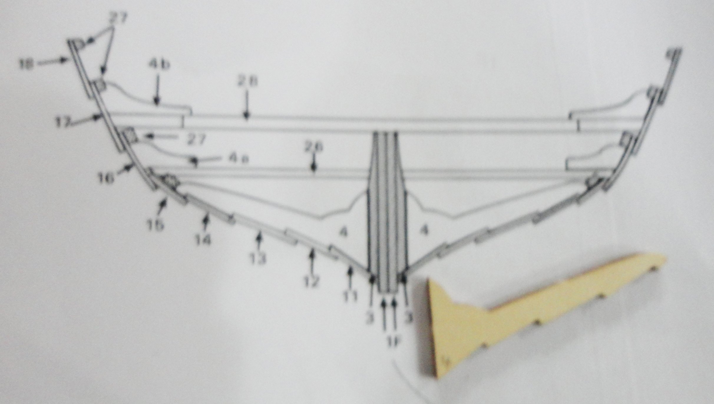
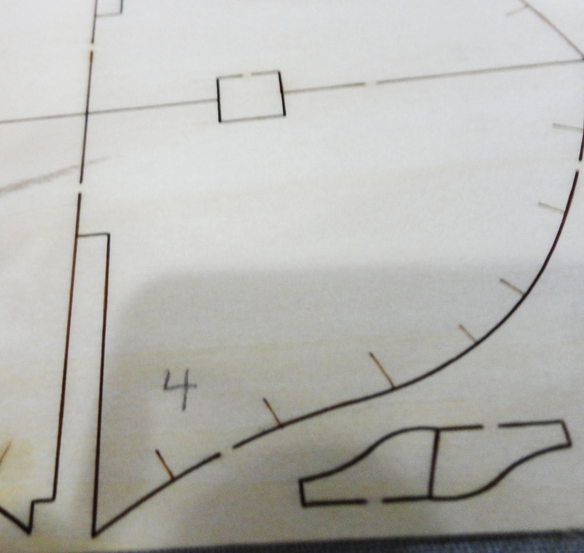
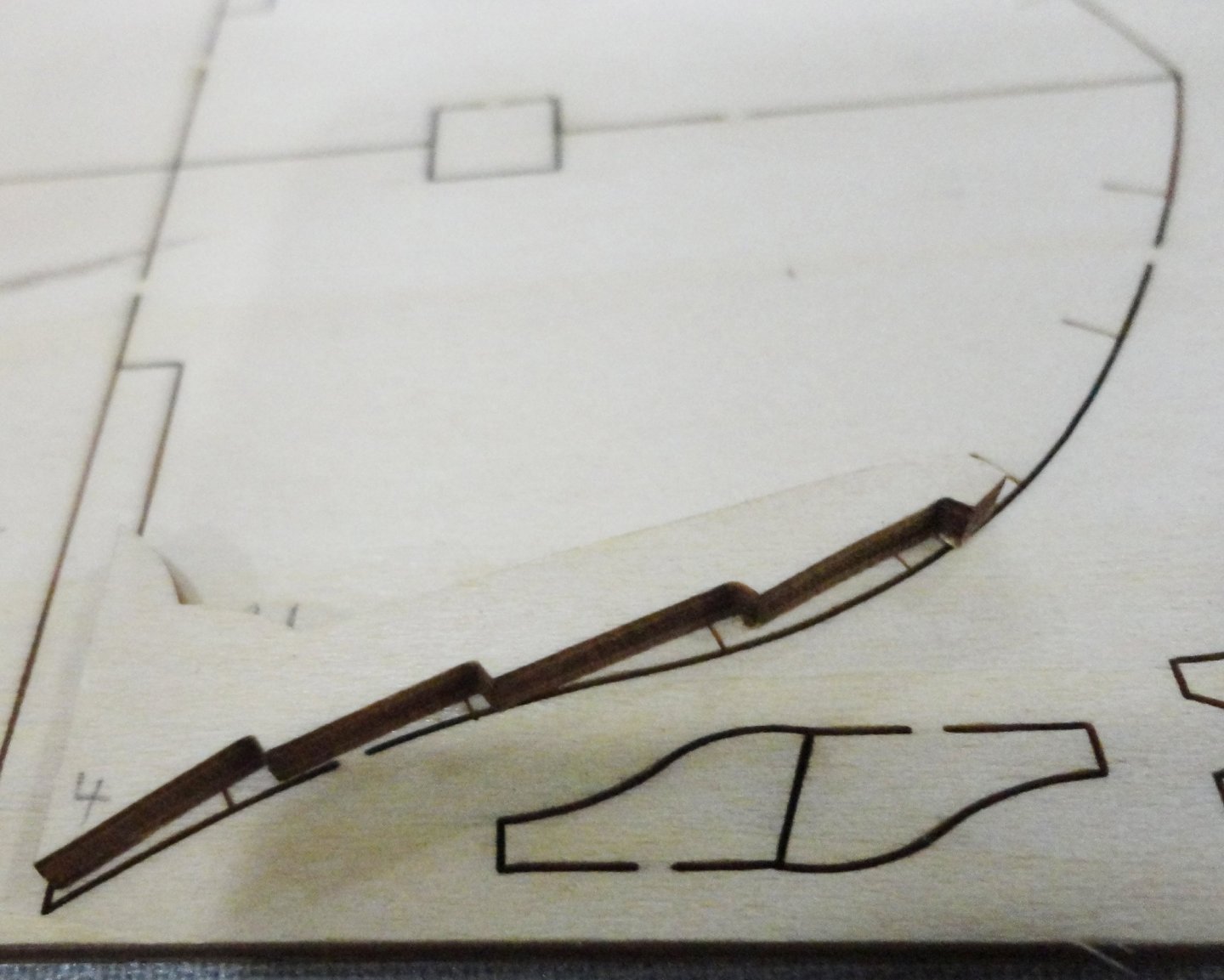
'Found that measuring the #4 rib to the rib size in the section drawing that the wood rib was 125% larger. Copying at 125% made for a match ... but here's where it gets tricky. A cut-out of the enlargement (full size on the model) does not match the curvature on the building bulkhead half #4. The enlarged drawing is wider ! Since the strakes are all pre-cut, making a wider bulkhead would cause the provided strakes to be shorter than needed. This would not be good. 'Guess the cross sections are there primarily for part # identification (also needed), rather than to depict the actual configuration of the assembly (otherwise known as 'true size and shape'). &$$%# !! OK - the provided bulkhead has to be used, and the idea of just overlaying an adjusted cross section drawing is out the window. And notching the bulkheads may be 'out' as well. I note that each provided strake (and the all have to be the exact one in the correct position relative to the side being built) is a specific width at each bulkhead point. The position of the 'tick marks' appears to mean where each successive plank ends with respect to the bulkhead. Some of these are close to where they should be, some a little off (depending on the plank). The area of overlap (where glue is applied to join the planks along their edges) is raised above the bulkhead by the thickness of the plank beneath. This will naturally lessen the change of accidental gluing to the bulkhead (unless too much glue is applied, then squeezes out when all those clamps are applied). It will take considerable study to adjust the tick-marks to the optimal position. Still, the wooden rib to be installed later is a good guide for those planks nearest the keel on where the tick-mark for them should be. The garboard plank bears against the extra layer glued to the keel, and represents the 'overlap' in that area. I'll have to measure each plank at the midpoint and note where the other tick-marks should be adjusted. Getting this hull planked turns out to be a lot harder than it looks.
- 146 replies
-
- 4
-
-
- Roar Ege
- Billing Boats
- (and 2 more)
-
I've imagined an alternative to formal cases - imagine thick shelves on one wall of a room (the shelves have the back edge right against the wall, and alternative to thick shelves would be two shelves - one on top of the other). One could hang plexiglass from the front and sides of one shelf (the lower one if there are pairs) going down to the one below. The hanging hardware would be pan head screws, and the corresponding holes in the plexiglass would be large enough to go over the head of each screw ... thus the panels would be easy to remove for access to the models (the height between shelving would be appropriate for the height of the models on that shelf). Most of the dust would be kept out, and perhaps only an occasional use of 'dust off' (pressurized air in a spray can) every 2 or 3 years might be needed.
-
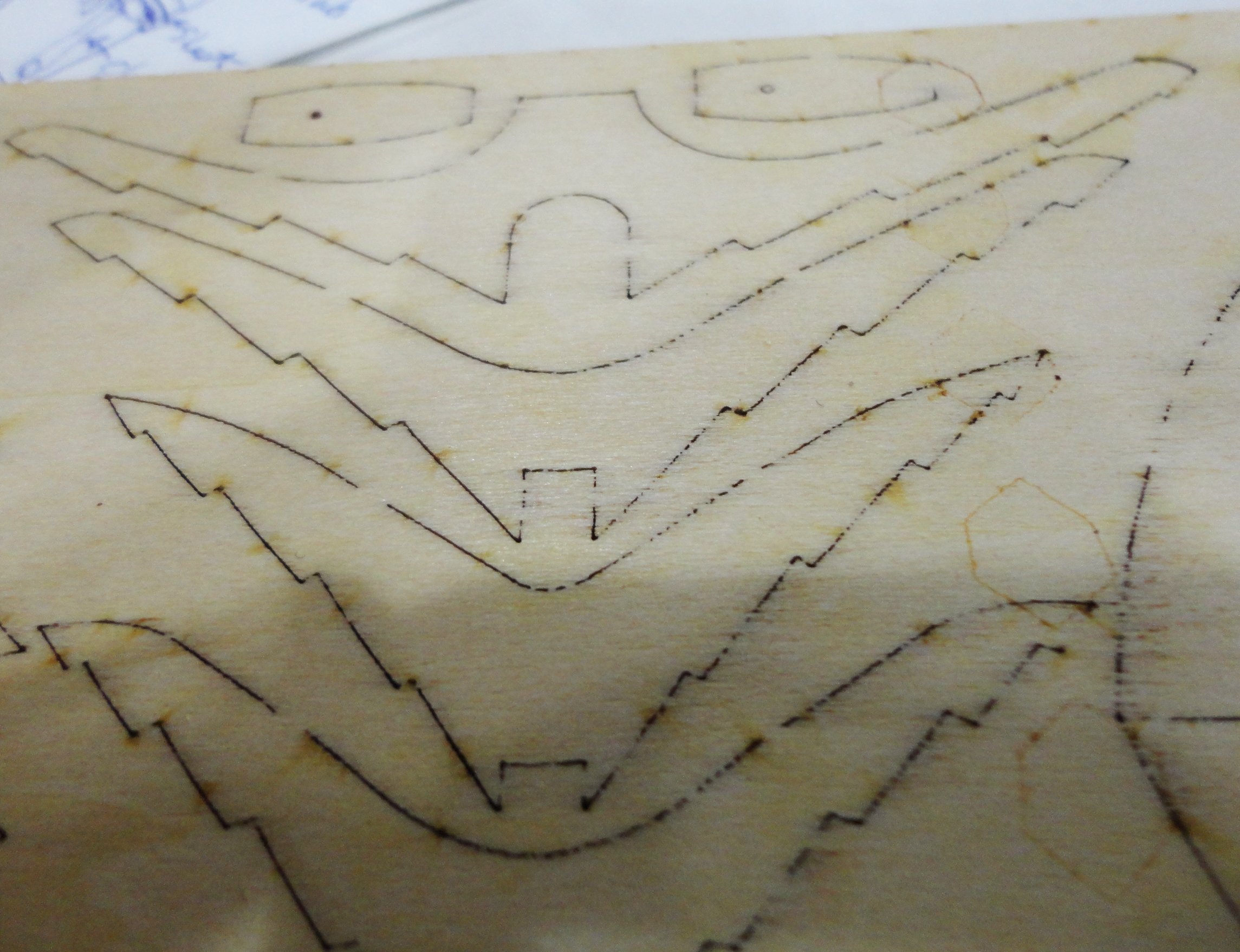
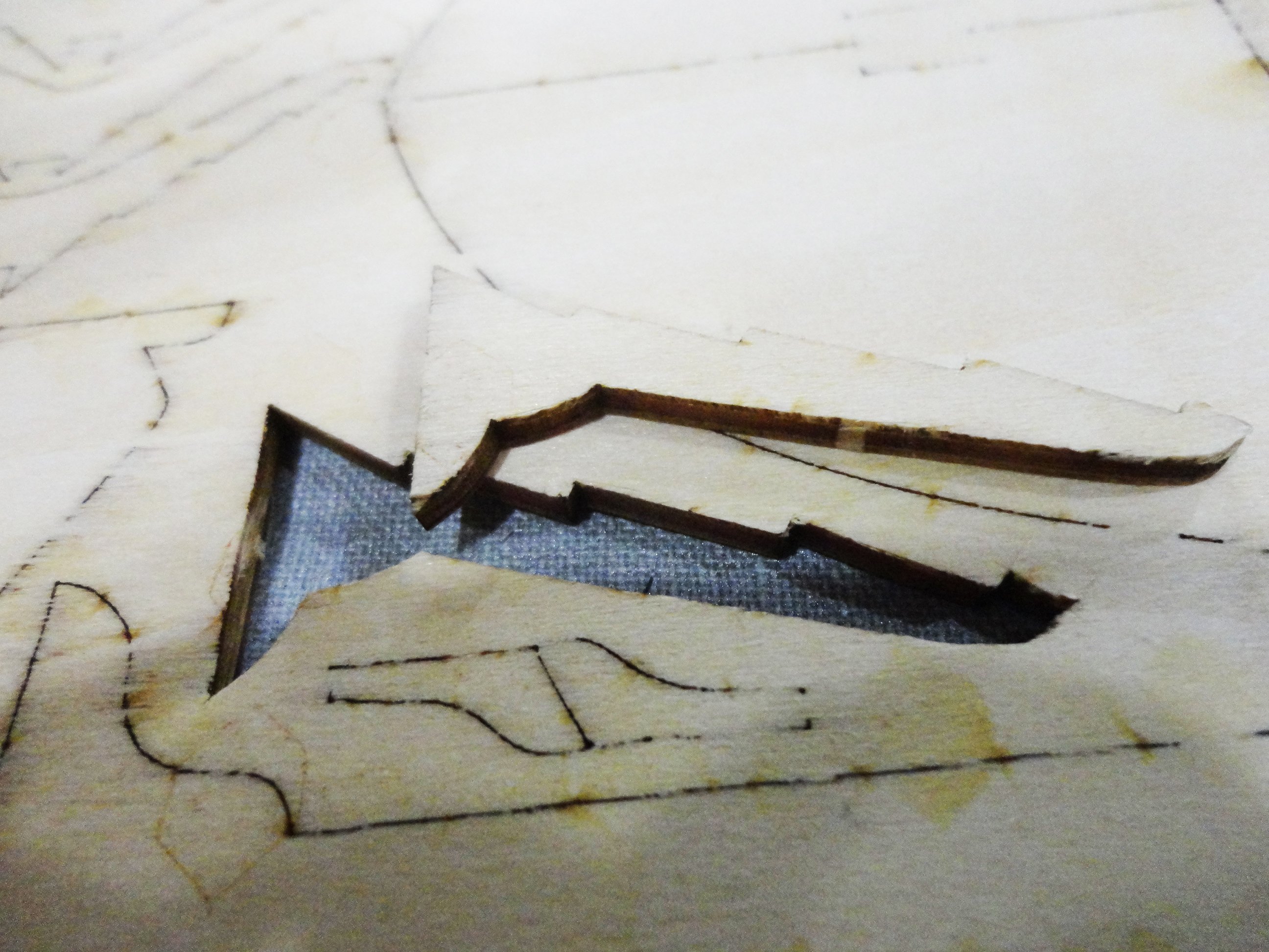
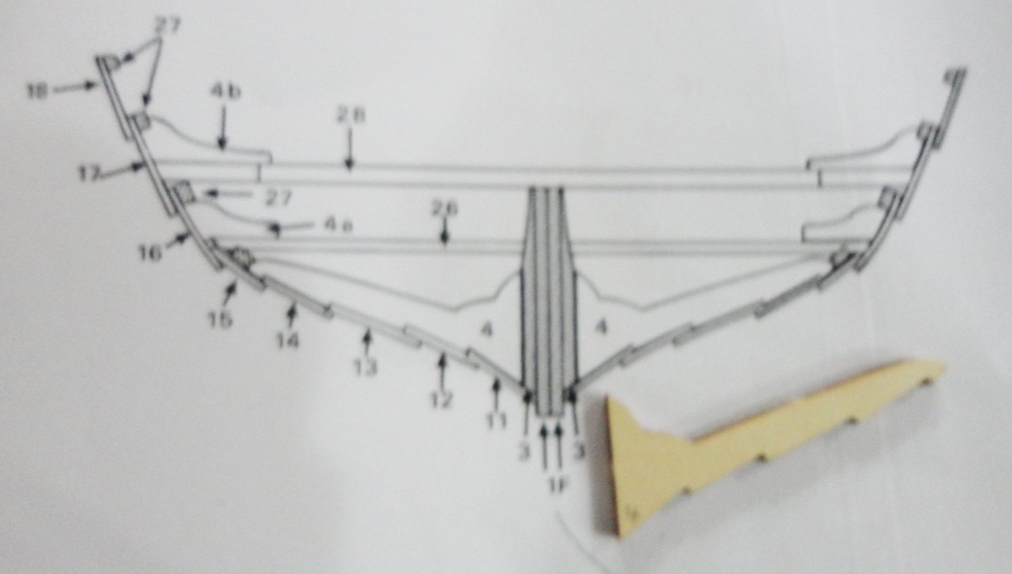
OK, I'm back at home now ... really, at 71 (and counting) I'm the 'poster child' for 'retirement' these days. Since there's some insecurity about outliving what savings we have after some setbacks in the housing 'bubble', I work per-diem as a Pharmacy Technician at our local hospital about on-par with part-time work. I'm also making hay of late doing much work in the yard and garden (well, this is the time of year to do it), and also some exterior maintenance. 'Thought I'd have to tear down the lawn tractor engine to replace the rod, but it was failing motor mounts that were at fault. Still had to replace the safety switches, key assy., solenoid, and adjust the valve clearances ... among a host of deferred maintenance - runs like a top now with 24 years on it. Enough of that, I took a few pictures to try and clarify my previous comments. As mentioned, the 'whole hull' jig would be quite a lot of trouble, as the building by halves jig can be vastly improved by notching the frames provided to match the ribs to be inserted later. Once can also 'bear down' on the fore and aft ends while tapering the ends of the strakes if built in halves. The first picture is of the BACK of the provided sheet, and you can see that there are plenty of fibers still crossing over the line of laser cutting. I think that this 'a little less' than full blast method is preferable to 'over char' that you can get some some other kits. I used a 'pointy' X-Acto knife (with a fresh SHARP blade) to trim around these fibers and also to go about half way (in 2 or 3 soft cuts) through the 'tabs' that hold the part in the matrix so it won't fall out in shipping/handling. The front face of the tabs are sliced next to free the part. The next picture shows the freed part, which was handled with care ... you've seen how they can get damaged otherwise. Now for the 'tick marks' ... yeah, I thought they might indicate where the top edge of each plank is supposed to go - but this is NOT the case as will be seen. They are the inward pointing lightly lasered (they just mark the surface) short lines along the edge. In order not to mix up parts, I'm numbering them lightly in erasable pencil ... and will also mark the place on the sheet where it came from. Said sheet can be a template if I want to build the boat in better hardwood ply made up myself from 3 or 4 layers of fine veneer with rotated grain. OK, now for the 'overlay' ... rib half 4 was placed over the building bulkhead half 4 to show where to mark the 'saw tooth' (using the rib as a guide) on the bulkhead that will locate and orient each plank as it is assembled. One will have to avoid gluing the plank to the bulkhead by not having glue get too near said bulkhead. (Wood glue will be preferable to CA to prevent 'wicking', and if that bonded planks to the building bulkheads, well, that would be a big complication.) Of course, this leaves one wondering how to mark the notching for the planks above where the rib ends. (I'll get to that.) The notching can be done by first making a thin inward cut with a model train track cutting saw, then paring with an X-Acto along the edge working toward the relief cut just made. Gosh, it would have been great if Billing has laser cut the bulkheads halves WITH correct notches. Still, what is in the kit (with a few caveats) sure beats scratch building. You just have to look at the glass as 'half full' instead of half-empty. If life gives you a lemon, make lemonade. I apologize that the next picture is a little out of focus, but you can see that the cross section provided is not to full scale (pity). But I'll use my copier to scale the drawing up to full size, and used the wood part as a gauge to prove that the size of the adjusted copy is correct. Then, instead of using the the rib half to mark the notching needed on the building bulkhead, I'll glue a half cross section right to the building bulkhead ... shazaam ! I now will have ALL the notches needed going right up the side of the bulkhead. Of course, they only provide 3 cross sections, so if I want to make additional bulkheads I'll need to make my own cross sections for those ... but will they be correct? The answer for that is that the added bulkheads do not have to go all the way up, but the ribs provided will be templates to make partial building bulkheads - if I go to the trouble to do them. Having the three critical bulkhead notched will 'set up' the strakes (planks) so that the path to either end will be predetermined. Its this sort of design work that stimulates my brain cells, so I should take a break from the tedium of making over 100 more rope coils at 1:100 scale on the GF and do some larger work. I used to be an industrial engineer until made redundant at age 51 - another story I'll skip. Trimming (profiling) the keel stiffener is also tricky, and I'll have to look into that. Another idea is to add a little material to the tops of the keel (part 1) forward and aft of the central stiffener (part 3) for the garboard strake to bear against. Said material has to go between where the ribs will attach, which is why I thought of making additional partial building bulkheads. With your permission, once I do a half-jig, I can post you pictures of what I came up with - if it will help.


- 146 replies
-
- 5
-
-
-
- Roar Ege
- Billing Boats
- (and 2 more)
-
Micha, you've got me thinking enough to take another look inside the 703 kit box, and made a couple observations: 1.) The laser cutting is a fine line, and the power tuned back so that there is not too much 'burn' - but then it doesn't quite go thru to the back completely in places. So putting a sheet on a surface with the back side up, an X-acto knife was carefully (very lightly) run around the perimeter, noting that there are a couple of connecting tabs to partially cut. Then the sheet was flipped to partially cut the tabs from the front side. Then the delicate part could drop out almost by itself with no damage. Care in getting each part out is essential. 2.) I put half rib #4 over the half building form #4 and saw where the form could be marked with a very sharp pointed mechanical pencil to file or cut-out 'saw teeth' to match the corresponding rib. The lightly burned 'tick marks' on the edge of the form don't seem to correspond to anything, thus shouldbe ignored. I must get to work soon, but can take a couple pictures that will show better what I mean. Building the kit in halves may indeed be the way to go - perhaps enhanced by a couple extra building frames notched as above. Then the planking can be made to fit the notches so later installation of the ribs will go correctly.
- 146 replies
-
- 3
-
-
-
- Roar Ege
- Billing Boats
- (and 2 more)
-
'Got my box off the shelf (and the main hull parts are elsewhere, as I've reproduced them - with modifications - in 1:88 to match the scale of the cannon), and it's HEAVY ... the weightiest kit I've ever lofted (aprox. 15 pounds complete). The drawings have the date of January 1st, 1975, ergo I surmise that the release of the kit could well have been later in 1975. There is a lot of 'bang for the buck', and if built 'out of the box' in 1:65 will be quite large and impressive - if not something of an anachronism, since the design of the castles is quite conjectural and they do not conform to either the depiction on the Anthony Roll or the painting Henry VIII commissioned in the 1530s. I'll make mine in 1:88 with a castle profile a lot like Louie da Fly's Henry Grace a Dieu (a log I can recommend reviewing, as it is accomplished in a much smaller scale - and masterfully done at that). The kit masting seems rather TALL for the hull proportions, and might make a ship built like that 'krank' (tending to heel easily - the 1628 Vasa being a prime example of the effect, to our benefit by raising and restoring the entire original hull). But it is easy just to build the model with slightly less tall masting. EDIT: Now I recall reading that the Great Harry DID heel too much in brisk winds, and that was why the stern castle was reduced to improve handling. The Mary Rose handled well as built, but the rear castle was raised and extra armaments were added prior to the action that saw her sink in Henry's sight. It is unlikely that a 'lucky shot' from the French did her in - as it would have to be below the waterline, and most likely on the side she settle down on ... the very one we have today, and there are no breaches evident. I rather think that the event was much like the Vasa debacle nearly a century later.
- 12 replies
-
- 1
-
-
- Great Harry
- Henry Grace a Dieu
- (and 2 more)
-
Should the jackstays be a little 'forward' on the yard, instead of top-dead-center? 'Haven't done any yet on a 1:100 project but will, in time, get to them.
-
rigging in front of yard arms?
Snug Harbor Johnny replied to paul ron's topic in Masting, rigging and sails
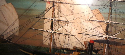
Looking at the portion of the picture the Admiral took, I can see that there IS bunching at the parrel points. Now (looking at the entire image taken) the steam frigate appears to be a Navy ship (white stripe with dark gun ports) that is flying the American flag from the spanker boom. I've tried to expand the image of the flag - and the resolution only goes so far, but there is either a 5x6 or a 5x7 array - corresponding to 30 or 35 states, respectively ... another reason to go back and have a close look at the original. (Note to Paul: this does seem to connect with the thread topic of rigging in front of the yard, so I hope it is of interest.) Wisconsin was the 30th state admitted in 1848, and Nevada the 36th in 1864 (ignoring states thought to be in rebellion at the time), so that might be the 'envelope' for the time depicted in the painting. I'll have to do research on this type of Navy ship build then (having the domes under which there are a paddle wheels). She flies a 'courtesy' flag on a fore mast back stay that is a "Red Duster" for Canada (a red flag with the union jack in the top corner), and also a blue pennant I need to get better detail on. In the background are fishing schooners such as seen in the 1937 B&W film 'Captains Courageous', so my guess is that the Navy ship is in fishing grounds off Newfoundland ... ? The composition stands out as an 'action shot' - not the 'typical' sort where an owner's named ship is represented. I'm not about to let this rest, unless the item is gone by the time we can get back there. -
rigging in front of yard arms?
Snug Harbor Johnny replied to paul ron's topic in Masting, rigging and sails
Thanks. I forgot about 'clews to the mast', and a portion of a photo of the painting (seem's the Admiral took it after I stared at the artwork) is pasted below. I'm tempted to go back and buy the restored painting, as it was about 2' x 3' and priced at $145.