Snug Harbor Johnny
-
Posts
1,502 -
Joined
-
Last visited
Content Type
Profiles
Forums
Gallery
Events
Everything posted by Snug Harbor Johnny
-
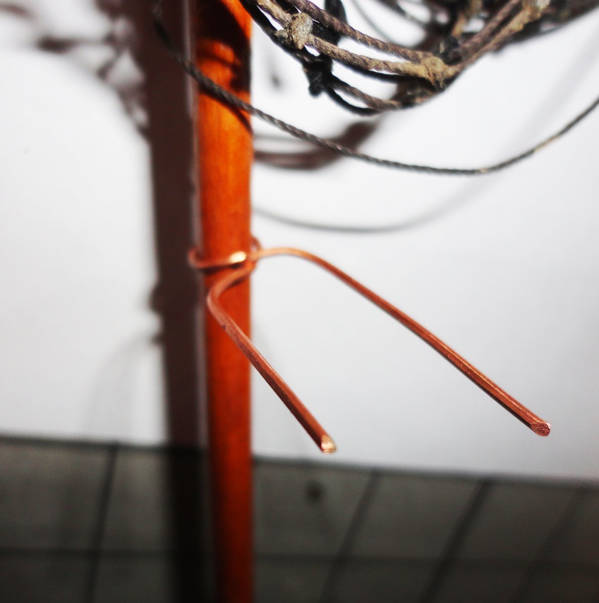
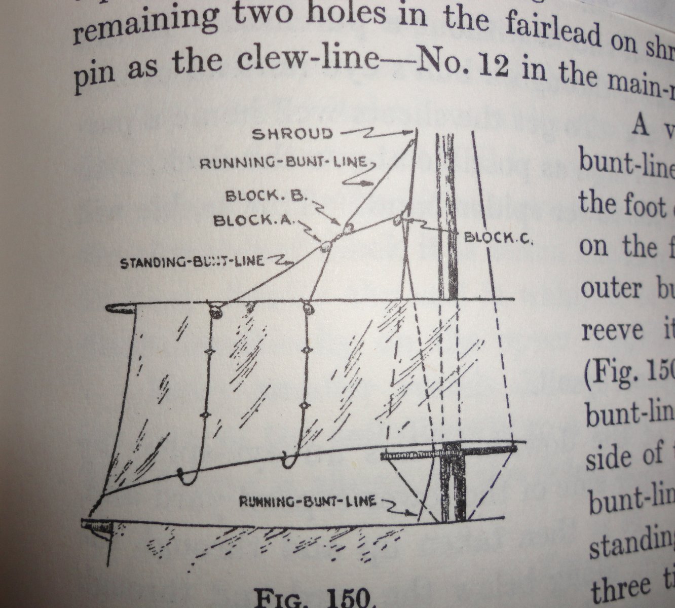
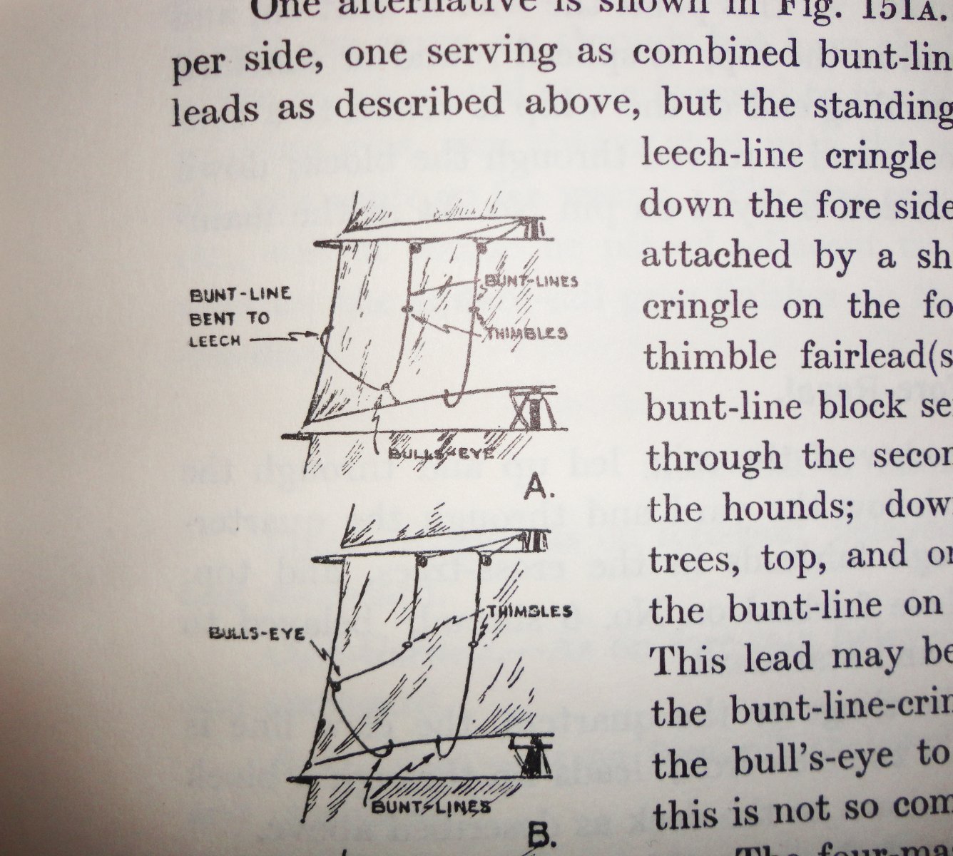
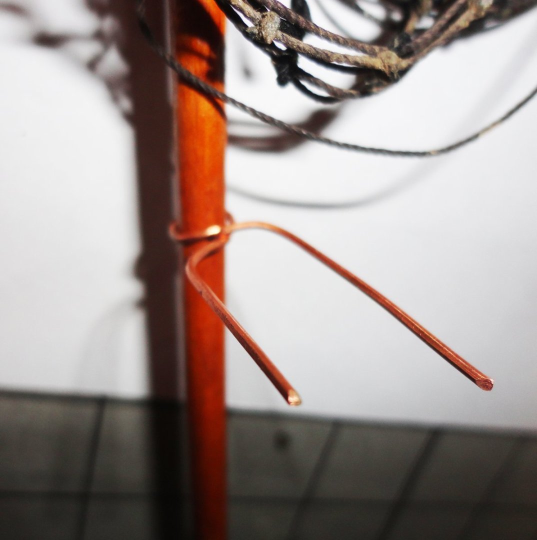
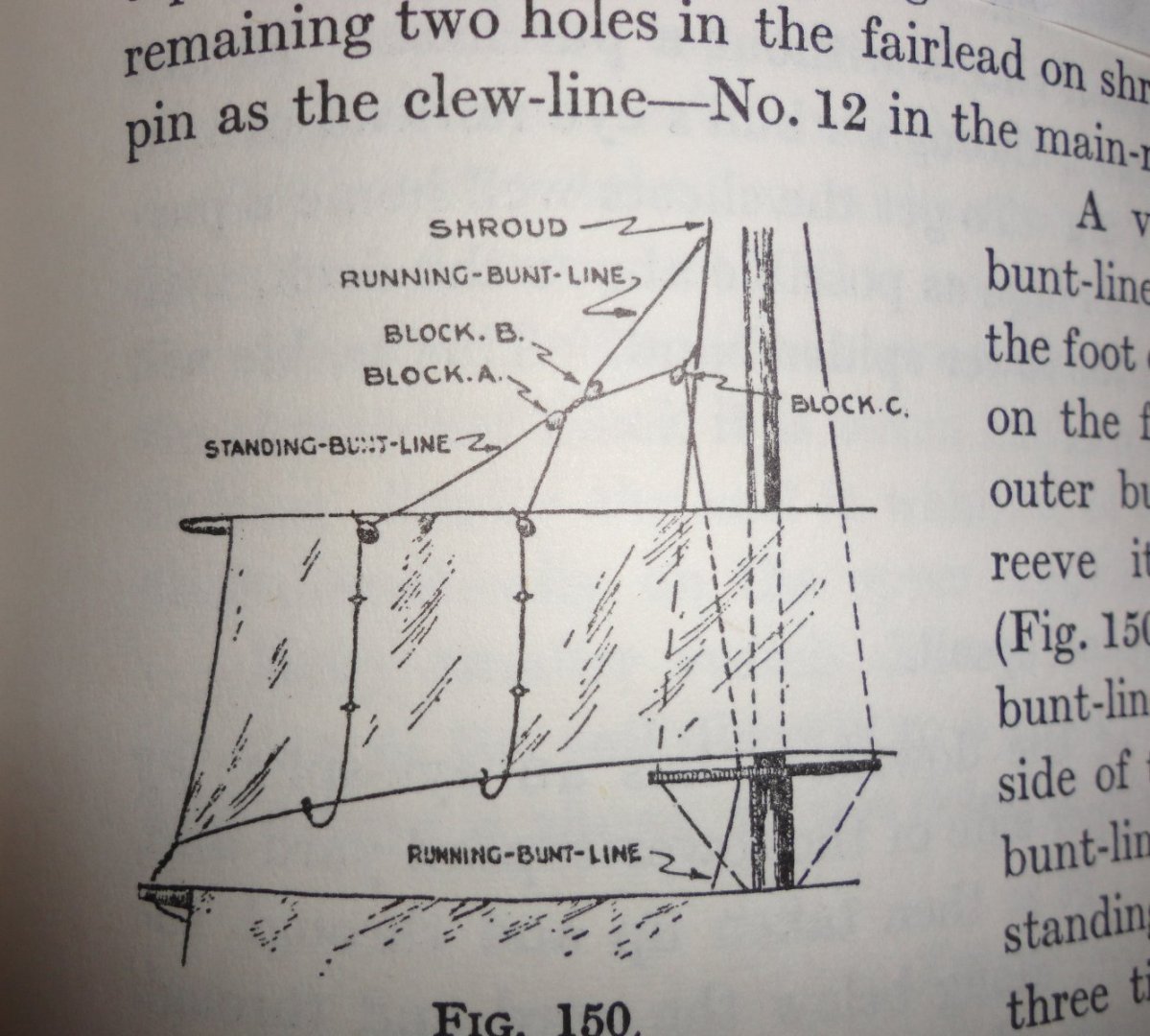
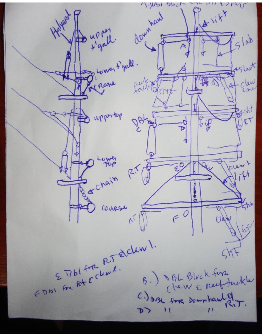
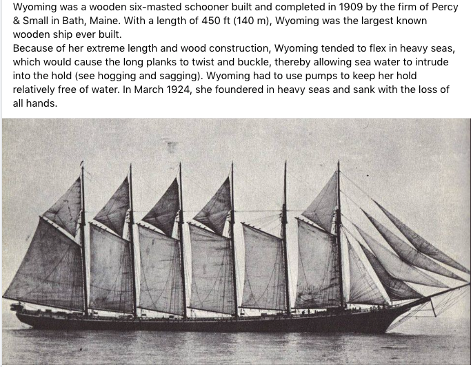
 Well, George .. I've been doing a lot of thinking about this. For one thing, I'm going to have to replace all of the lines - most likely with scale rope I make on the Rope Rocket. Yes, it will be significantly reduced in thickness - but not entirely to scale. Now that the fore mast has been removed (and it proved to be relative easy to do so), I see that the upper sections are thicker than if 'true to scale' - and the yards are also thick. But is this really a bad thing? I won't replace the masting, if only because it would get too far from being a restoration. Yet a 'faithful' restoration would be to change as little as practical. I'm compromising on something 'in between'. I note that the sails are sized wrong (compared to the original ship), but those are the ones that I'm using since they cleaned up nicely and someone put a lot of work into them ... I can only hope that at some future time in my semi-retirement that I can make a Thermopylae more closely imitating the original (also with the barque rig, yet before she was painted white prior to sale to Portugal) ... see, when I saw the present model at a distance it made me think of the 'Big T' in white. I do have a photo of Thermie converted to barque rig, but still with the original hull color. Its noted that the mast I have to work with is fairly stiff and resists bending. It is probably due to being a.) made of sturdy dowel - as not all dowels are created equal, b.) is somewhat out of scale in the upper sections, and c.) is coated thickly with varnish that may add a 'monocoque' effect - not unlike early aircraft whose strength was enhanced by a metal skin over the framing. It makes plastic masting/yarding seem rubbery, as late editions of Revel and Airfix ships often turn out to be. Even the original version bend too much. I see great advantages to using well-chosen wood. The plan right now is for the course yard and lower topsail yard to be fixed (as usual) - with (for simplicity) will used copper wire bent a shown in the next pic - the upper topsail will have a yoke and parrel, then a fixed lower topgallant and a moveable upper topgallant. Sure, this isn't 'right', but its pretty much how the model was made and its the hand I'm dealt. During lunch at per-diem work today I made a crude sketch . The masting can have a hole for the halyard of the two yards that will be setup as movable. The lower topsail and topgallant yards will have a crane, and the course yard will have a chain. This will be better than just 'tying the yards to the mast' with line as done originally. The upper topgallant will have a slack lift (since it will be raised), simple downhaul tackle, no clew lines (per Underhill) and the sail will have a slab line on either side - so the blocks on the yard near the mast will be double blocks (for the down haul and slab line on either side). I want to take advantage of (as shown in Underhill) how two bunt lines can be merged into a single control line ... and also how the leech line can be combined with the outer bunt line (in one of 2 ways). This can reduce three lines (leech, bunt and bunt) into a single line to go down to the deck .. thus greatly reducing the amount of fairleads that get drilled into the top above the course yard. Now bunt block were like something like 6" blocks (150mm), so using 1.5mm seed beads (perhaps 2mm) will be adequate for these - and other 6"blocks. 8" blocks would be 2mm at 1:100, but I have some that size and appear daunting to work with - but a compromise at 2 1/2mm can make things easier. Now the yards below can have a hole drilled near the yard ends for the sheets of the sail above - routed to a double block in the center of each yard and thence downwards in front of the mast (no fairleads needed except for a couple on the undersides of the yards). Since the yards are a bit thicker than need be, I'll have to see what to do about mounting jackstays and foot ropes (not shown on the sketch). Worst case I can bend the sails to the yards as was done originally and omit foot ropes ... but either would be a nice enhancement, and practice to see if my hands can do the work. The lower topgallant is the highest sail to have reef points, but (per Underhill) being fixed it has a clew line - so the double block on the yard near the mast will be for the clew line and reef tackle. The yard below, being movable, will have a double inner block for the down haul and reef tackle. The lower topsail yard below that .. a double inner block for the clew lines and reef tackle. With these simplifications, I'm counting only 11 lines on each side that would pass through the top above the main course yard ... not exactly Swiss cheese. 'Early days yet. I figure on learning as I go (still waiting for the Seamanship manual) and solving snags or re-thinking as needed. And I also have to think about what I have to do on the hull and deck areas once the masting is cleared away. A lot of time to go in 'dry dock' ! Johnny PS ... Speaking of scale, the ship pictured below of some 450' would have about a 54" hull modeled at 1:100 ... a whopper.
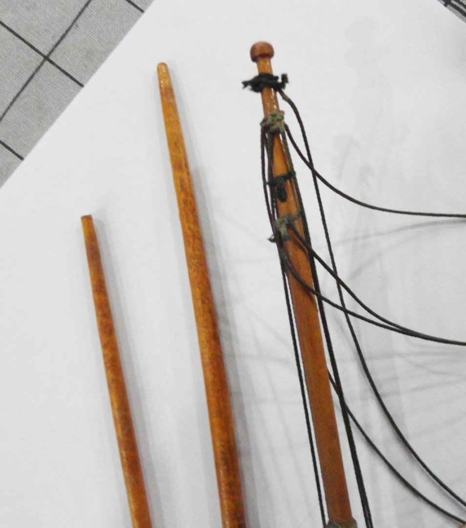

-
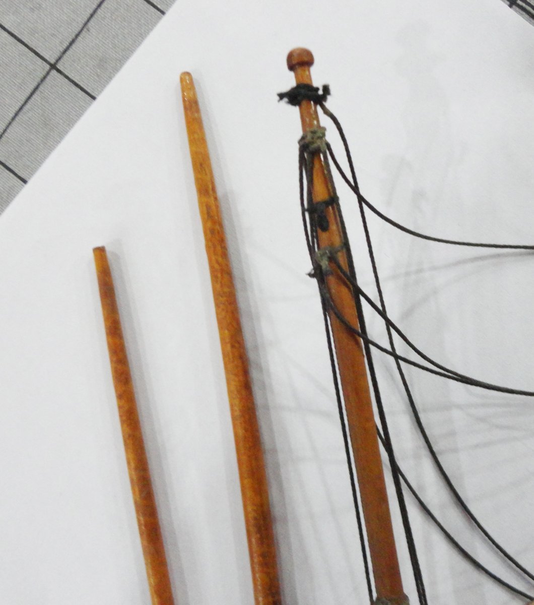
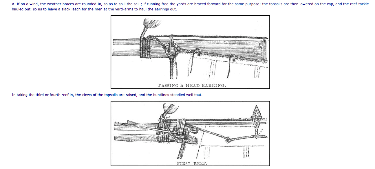
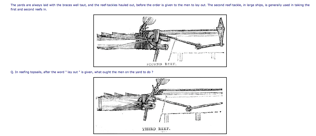
Edited NOTE: I've mistaken the title quoted below (readily available) with the ACTUAL title - The Boy's Manual of Seamanship and Gunnery , originally published in 1861 (author C. Burney, publisher Trubner & Co.). This is apparently a rare , collectible book and not readily available. Abe books offers a "print on demand" from India of the 1871 edition of the book (with shipping comes to about $30). So I've ordered one by first logging into my Abe Books account and paid by credit card to have them manage the transaction. This, method avoids having to deal with an unfamiliar seller overseas. The reprint of the 1904 book was received, and primarily deals with the Royal Navy life circa 1904. There are some illustrations of rope work and tackle as was still in use at the time, but not focused on sailing ships. Once the copy of the 19th century book is received, it will be a different kettle of fish - with more pertinent information on square-rigged ships. Still, there are portions of interest in the early 20th century book top peruse at leisure. I can comment on the copy of the older book once received. 'Just found a couple of illustrations from a book originally published in 1904 titled "Manual of SeaManship for Boys and Seamen of the Royal Navy" ... and on the strength of the illustrations, a 'like new' copy of a 2010 reprint was ordered through Amazon for $20 (plus tax and shipping). 'Looks to me like each stage of reefing omits aspects of the previous stage for clarity. I hope to learn more about rigging with sails (supposedly gunnery and ship life are also detailed in the book), as my restoration will have the sails set as pretty much as they were on the model as found - with some enhancements. As predicted, I was able to winkle the fore mast right out of its snug-fitting hole in the solid hull - and this will make working on the hull FAR easier, as well as pre-assembling the yards with sails to the mast and a certain amount of the rigging that will pass through fair leads. A couple more photos should accompany a subsequent post. The yards were originally just tied to the masts on the model, where the fixed yards on the clippers had various types of metal pivots - and the movable yards some kind of yoke. At 1:100 (and also having less skill the exhibited in high-level builds of the Cutty and Flying Fish, to name only two) as well as the more basic aspects of the original build that I do not want to mess too much with, I may bend a length of copper wire to go around the mast, then twisted once with the free ends curved forward to pass through the yard. This will hold it away from the trunk of the mast, yet pivot to assume the position the yard would be in with the wind coming from a stern quarter. (Each yard above will have a slightly different angle as explained in several other builds having sails.)
-
'Simply stunning ... in that I'm stunned by the superb workmanship on your Cutty. Kudos !
- 399 replies
-
- 1
-

-
- cutty sark
- revell
- (and 2 more)
-
i'll put in a comment for Artisania Latina parts/accessories ordered from their website. Paid by Paypal, the parts got to me from Spain in 1 week. I suppose a kit might take a little longer, but they are also carried by U.S. dealers.
-
'Had a look at a sail with reefing lines, and the 'flyaway' appearance is something I tried a recently posted method to fix. Step one is to approximate a straightened look manually - just a little moisture on the finger will help, as it does with hair. Step 2 is to use a convenient tool (in my case a dental tool) that has been dipped a little into clear shellac to apply as shown to a reef line that is off of the sail. Another tool such as a tweezer held in the non-dominant hand can lift the line as needed. Note how the line just absorbs some of the shellac from the tool. I did goof and either the bottom of the tool touched the sail (or a little shellac dripped off), and this will cause a faint spot. So the solution was to dip an end of a Q-tip into alcohol (the shellac solvent), wick off any excess on a paper towel then apply to the shellac spot before it dries. Flip the Q-tip to the dry end and wick up alcohol from the spot, which will bring some of the shellac with it. Repeat, and whatever shellac remains will also be spread out further and not be noticed much. So my procedure is revised to wipe the bottom of the shellac bearing tool so the stuff only gets wicked onto the line. Then the dental tool was flipped and I used the differently contoured end to gently press the line against the sail as it got 'tacky' ... and it did adhere (but can be pulled away if desired). The last shows the straightened lines next to some that have yet to be straightened. I'm OK with the improvement, but the lines that happen to be on the sails is as light as the sails - so they tend to 'blend in'. My next ides is to used a very weak water color to slightly tint the line. The water will dry and the alcohol in the shellac to then be used for straightening won't bleed the color. I've used this technique on other projects. 'Did see that a couple lines are longer than some others, so I lifted just the ends of straightened lines, and trimmed as needed (not shown here).


-
Looking at two photos of actual metal plated hulls (as seen from a few yards away ... which might represent someone taking a relatively 'close' look at a model), the appearance is quite smooth. Seriously, the outlines of the individual plates are barely perceptible - and the tiny nails are all but invisible. Sure, if one can get right next to a plated ship in dry dock - close enough to reach out and touch the plates - you can see and feel the overlaps and nail heads ... but for a model, one would have to go through 'Wonka Vision' and be shrunk down to HO scale to get that close. A miniaturized person examining a model plated with individual copper plates would remark how thick the plates are and how large the divots (representing nails) are. On actual ships the copper (or Muntz metal) is, what, 0.032" ? At 1:96 you'd need 0.00033" (that's 1/3 of a thousandth - less than the thickness of a human hair ! ) material to be in scale - and 1/8" nail heads would shrink to only 1.3 thousandth of an inch - about 1.7 times an average hair thickness. (I'm not going to convert to millimeters.) Of course, there are many scale compromises that often are made in many scales - meaning that dead eyes, blocks and belaying pins often are are a bit 'out of scale' (sometimes more than a bit), so I suppose that plates and copper tape are no exception. 'Seems that on a solid-hull model (or a completely 'filled' plank-on-frame below the waterline, one could merely use a fine stylus (with a straight edge as a guide to follow very fine layout lines) to scribe rows of plating and then add vertical division. An X-Acto knife would also work. Spray painting a brownish base coat followed by green overtones would be perfectly acceptable for the bottom of a hull - which is not where most observers are looking.
-
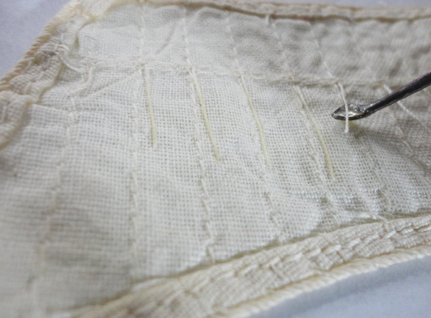
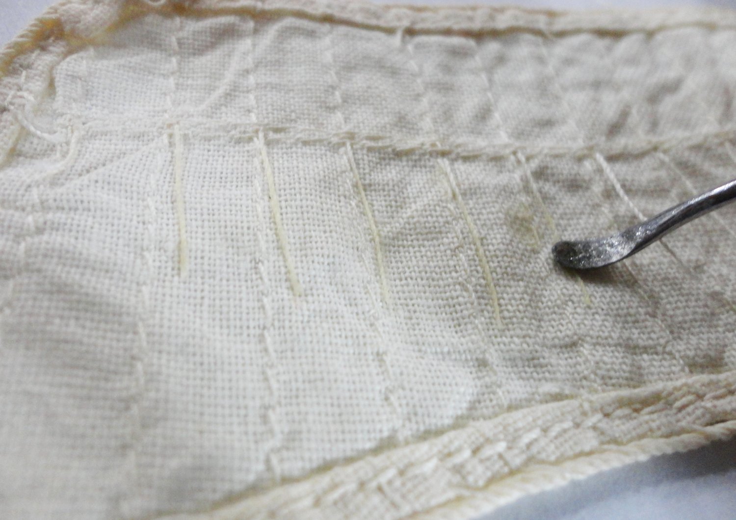
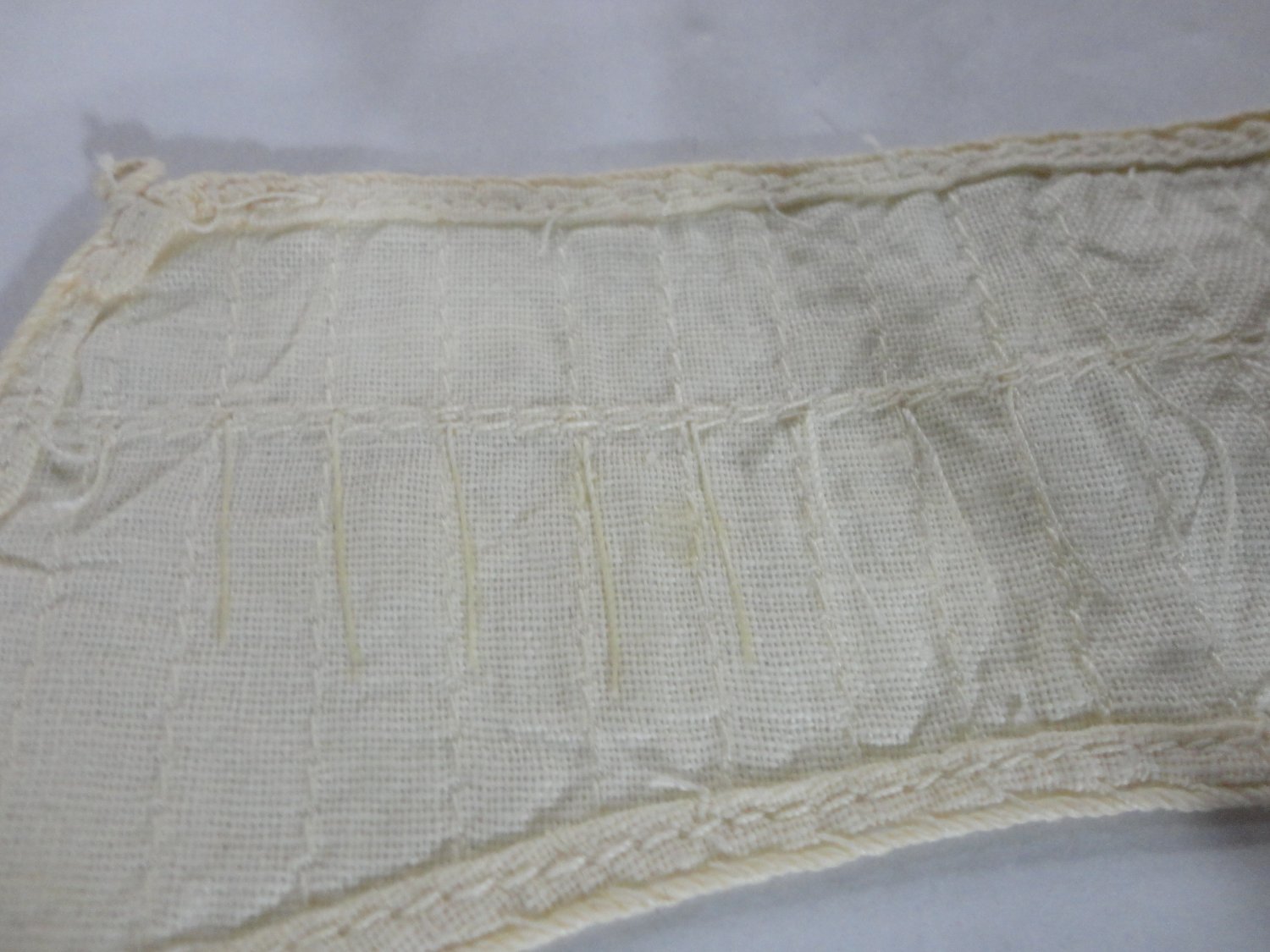
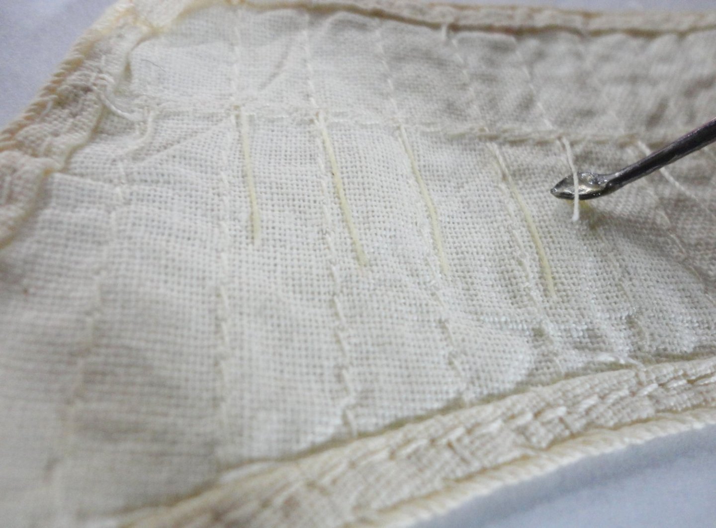
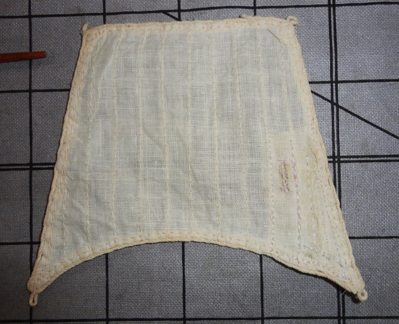
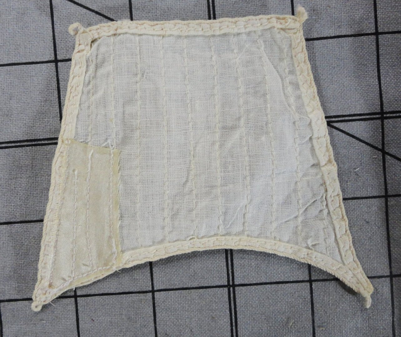
'Time to jump in and clean the rest of the sails on the fore mast. The most convenient way (with some care) to remove the sails bent to the yard was to utilize a seam ripper as shown below. BTW, the drawing specifies a silk shuttle Admiralty order to be made of aprox. 1/8 thick stock. The same method of lightening was used as before, but 4 sails were processed together - same result. The yards were dirty, and plain water would not remove the grime. So I thought to try denatured alcohol (presuming the shellac was used on the yards) - which should have softened the shellac and stripped off the grime. Nothing doing - so it became apparent that a varnish had been used (proof against alcohol). SO I tried a little MEK 'substitute' (too bad I can't get the real MEK anymore ... should have stocked up on it and genuine trichlor while I could), which said was a 'stripper' for some paints/varnishes. It seemed to work with a little pressure and working. Since I didn't want to remove too much (like down to the wood, which did not appear to have been sanded very much ... but then the yards WERE nicely tapered, so perhaps some of the grain was raised with age) - so a wad of 000 (or was it 0000) steel wool took care of most of the remaining discoloration, leaving vey nice yards with most of the original varnish in place. 'Sorry that the focus is off, but one may notice a little damage (after my repair) on the top gallant. This happened by mishandling that sails while still wet from cleaning. 'Seems the sail fabric is actually a linen gauze (per the Admiral, who knows textiles - being an historic seamstress/costumer) that is fragile by nature - but more so when wet. There are many kinds of light fabric (like many flannels) that can be evenly torn along weft or weave just bu evenly pulling with both hands. So how to fix (once dry). Per another thread where 'clear' shellac was suggested to use on reefing line to keep straight, a very small amount was tried to seal the sedges of a nasty parting near one edge and a smaller tear on the next (simulated) panel of the sail. It seemed to 'seal', but even clear shellac has a faint tint, and I could see the area treated once dry. A better product to use that dries almost invisibly is "Fray Check" - sold at JoAnn Fabrics and many other craft or quilt shops. A narrow very light cotton patch was sewed to the reverse, but I wasn't satisfied with the lightness of it once done (not un-doable). A modern machine with variable stitch lengths was used - as there was a need for small stitching. But attempting to use narrow 'zig-zag' on the smaller tear only made it worse, as lateral forces moved the treads that were 90 degrees to the zig-zag. OK, so I found some 'blonde' natural fine silk that was a better match for the sails post-cleaning and made a larger patch to be applied to the back. Pre-turning the edges of the patch would have made for a better repair (should another be required), but the situation was acceptably resolved. Below are pictured of the results from the front and back. I've seem old photographs of clippers where repairs have been made to some of the sails - as well as joins and differences in appearance among panels of canvas used. Perhaps I can move this sail to the top gallant position on the main mast. These are 'first experience' from which I'm learning a lot. Now I'm going to proceed with the restoration since a.) It is something that can be completed in less time than either of the two incomplete builds I have logs for. b.) I wan't to get some experience with rigging at 1:100 scale (applicable in other scales as well) since the other two builds are either at or close to that. c.) There will have to be a display area set-up in the parlor (cased or not .. a like the idea of being able to closely examine the finished project - although an application of 'dust off' may be needed from time to time) - as one side of the room will ultimately be needed for other works in the future ... a trophy wall?


-
Yes, there are challenges ... but there are some advantages. First, there is a model under all the accumulated grime - so I with some care it can be partially de-constructed and saved as well as improved (within reason). As mentioned earlier, my main interest is in learning about rigging - perhaps not 'dead accurate' or 'painstakingly complete' as some are able to do. It only has to be 'good enough' for my satisfaction. Some yards will be in a fixed position, so I'll likely use jeers for those that will be in a raised by halyards. I don't want to drill holes in any of the masts.) I'd like to save the shrouds (and maybe the backstays), with lighter ratlines put in last (method TBD). Once the masts are out, I can try rigging them 'off model' as Rob has shown on some of his builds. lets see, sheets will go down to tackle at deck level with deck eyes added for the lowest blocks plus a pin rail around the mast to belay the lines. Clue and bunt lines should rout through fair leads to pins I'll add to the rail. Braces will be done as convenient. An advantage to a barque is that there are no square sails on the mizzen. Typical clippers with square sails on all three masts must have the mizzen braces go forward in the same area where Main braces run astern. This makes for a "cat's cradle" appearance (slightly 'gimpy'). I do have to think about the in and out haul lines for the staysails and jibs. Note that the GF does not have catheads (nor 'whiskers'), thus far fewer lines in the bowsprit area. I will have to fashion a longer bowsprit so it can be firmly set into a drilled hole ... the one made for the model snapped and was re-glued at some point, and is a vulnerable feature on any clipper model. Hmmm, maybe one of metal (like the original) might be less vulnerable. Once again, as has been my tendency through life, there are competing interest/projects for me to bounce between. Yet 'thinking about' about something for a long time before actually doing anything about it often results in a better outcome. I've always been good at 'following instructions' and thrive in a structured environment, so for things I find myself 'in the weeds' about - I have to 'create my own instructions' in an unstructured setting in order to go forward.
-
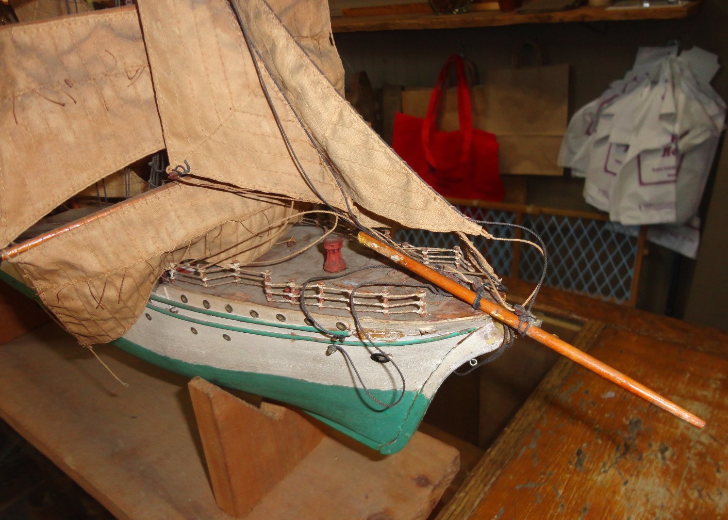
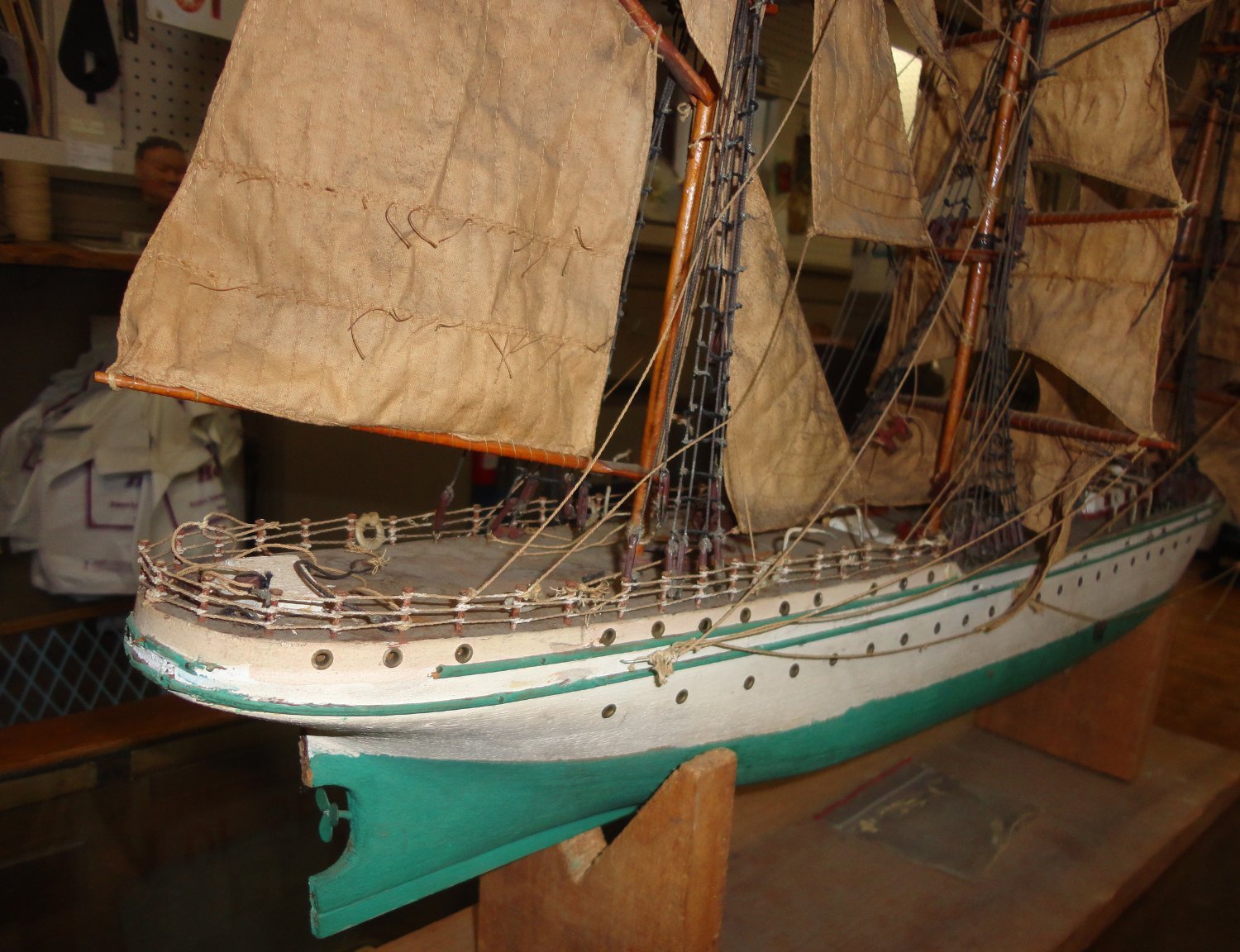
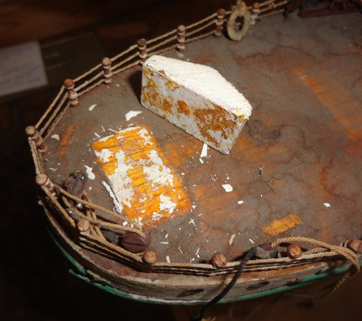
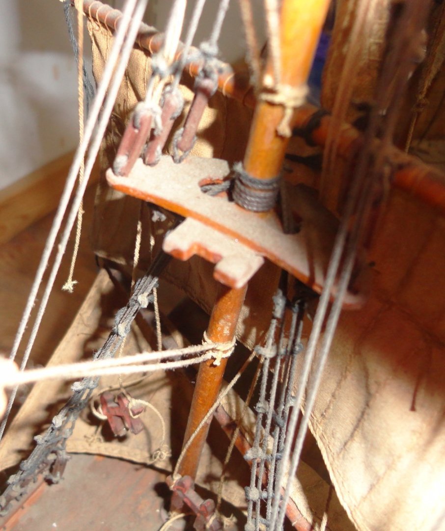
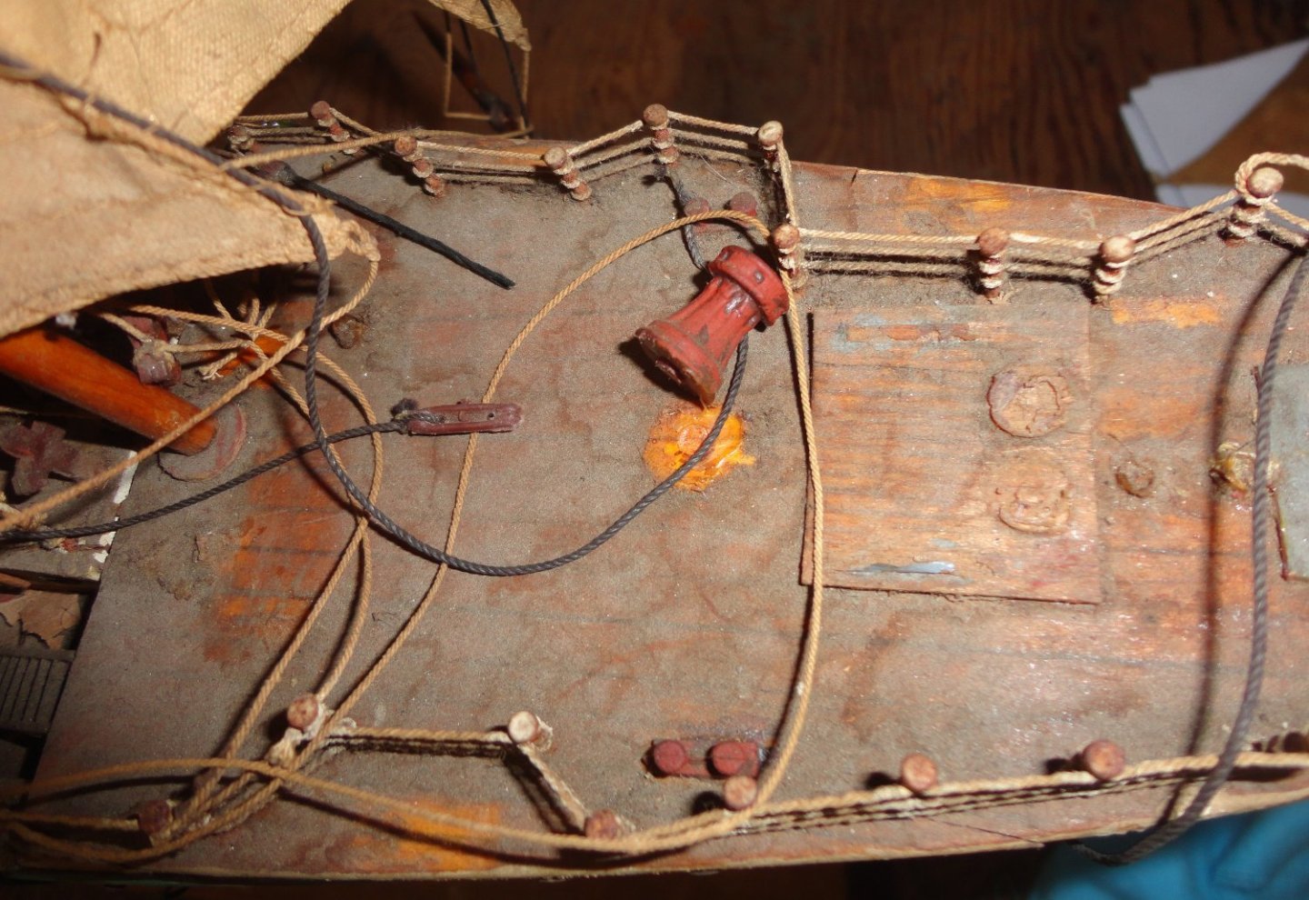
A mental 'plan' is being formulated - perhaps one I should write down - on how to proceed. First should be dismounting the yards and sails - cleaning the sails as already shown and keeping them together with (cleaned) yards in labeled envelopes so they don't get mixed up. I pondered the delicacy of working on the hull with the masts in place, then tested them carefully and ... I was able to turn each one a little, indicating that they likely were never glued in place - snug perhaps, but the rigging is holding them down. This may be my lucky break, since after freeing all the lines it seems that the masts can be winkled out of the hull - making restoration much easier. So I'm likely not to glue masts in on future projects, making life easier for some future restorer (if any). With a moistened corner of a flannel piece ... (BTW, I've been advised not to use the word 'moist' in mixed company unless it is to describe a cake: e.g., "Mrs. Johnson, you've baked a moist cake.") ... I tried cleaning the dirt off a small area on deck. And again luck is on my side, since it was first marked (pencil?) for planking and then given a coating of regular (amber) shellac. I've said on occasion that I'd rather be lucky than smart (although sometimes I'm neither). This means that the dirt will be relatively easy to lift off without staining any wood underneath or working dust into the grain. I love shellac, as it often makes a good 'spit coat' on woodwork to be painted. Once can also apply shellac over wood after oiling or any water soluble colorant or markings are applied, since shellac is alcohol based. Once the grain is sealed, no worries mate. So this is another 'note to self' that either amber or clear (blond) shellac on decking will keep out future dust/grime. One should note that things won't glue well after such a treatment, but then I've seen several models where items were just glued to bare wood and had failure. If one is going to pin deck fixtures firmly wooden doweling may be preferable to metal pins for wooden items, since the wood-to-wood bond between the sides of the pin and the objects being glued will be strong (and a pinned object is often removable). Either method is far better than relying on glue holding end grain. So I 'tested' a miserable little wheel shed (perhaps not original) and it 'popped' off of the shellacked deck - perhaps since it looks like a 'Duco' type cement was used (acetone based). Now it is obvious why so many things were already off (or missing) due to mere surface gluing. Something with a large surface area (like a deck house) could be glued to a deck prior to protecting with shellac. The tops have lubber holes, but I'll have to drill fairleads for clue and bunt lines. Having the masts off will make it easier to pre-attach the needed blocks. The metal fittings (in lieu of deadeyes) may be reused since they don't look like dead eyes - which the GF may never have had, but turnbuckles. What I'm seeing looks like something in-between. I suppose that better looking turnbuckles could be made on a miniature lathe. Below is a cross tree - all the masting appears shellacked, and I may leave them that way - perhaps painting the very ends white. The image below shows the forecastle - lots to fix or replicate there. The port side does indeed have the resting place for the traditional anchor, while the starboard anchor was the modern kind that was just pulled up against the side of the hull. The indentation in the railing further astern were for the port and starboard lights (missing). My 3 projects will, no doubt, be done piecemeal over an extended period of time. Fair sailing !
-
Good questions ... One thought is to gently go over the paint thats there with automotive rubbing compound to smooth it somewhat (no way would any sort of 'sandpaper' do - as the eyelets used for portholes stand slightly proud, as do 2 rub rails. I don't want those eyelets to be bright, and perhaps they should be touched up with white paint. I'll have to gather what early photographs I can of her before making any decisions. As a last resort, an overpainting could be done. Careful masking would allow a thin black line to be painted at the waterline for 'sharpness'. The surface could then be made semi-gloss with a little wax. A better screw should replace the thin, tin one cobbled at some point (whether original or not is unknown - the builder did use some cast metal fittings on the deck, and there were cast props available at the time. The rudder is gone, so need replacing, as do many deck features. Restoration v/s Rebuilding ... I guess there will be a mix of each. If 'only' restoring, the sails would be bent back on the yards (there are no jackstays or foot ropes on the model) and the very simplified rigging scheme would be used ... and the little nails with wrapped thread for railings would also remain (although re-strung). There would be the antique 'charm', along with all the clumsiness and errors of the original. If 'rebuilding', then almost everything would be re-done to try an improve accuracy (as much as possible for a 1930's configuration, v/s the ships present museum state as modified in the interim) ... but much of the 'charm' would be lost, without achieving top-notch accuracy (beyond my intermediate - at best - skill level). Each of these options represent opposite sides of a pendulum swing. Perhaps I may do something 'in-between' the extremes. The builder did not have the resources of the MSW, yet went to considerable lengths to do the best job at the time. Repairing and restoring the hull and masting without too many changes (but those railing DO need upgrading) would respect the original work. Augmenting/correcting the rigging (learning how to do reasonably proper rigging is my primary interest here) would be consistent with the care done on the sails themselves. I'd like to consider jackstays and foot ropes for the yards (we'll see) , and bunt lines for the sails. Bunt lines and halyards (where applicable - there are none presently) would be routed as typical to belaying pins at deck level. The solid hull does have a nice 'heft' to it. An improved stand is needed, since the one its on new is very crude (likely not original). Yes, cleaning all the sails will take time, but that becomes available amongst the various things I'm juggling in semi-retirement.
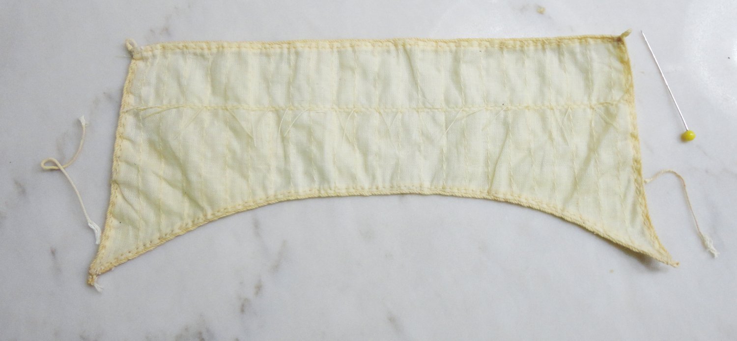
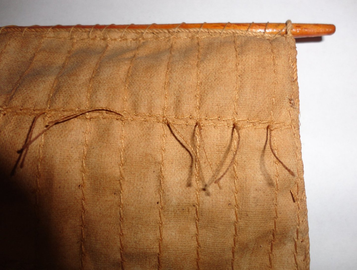
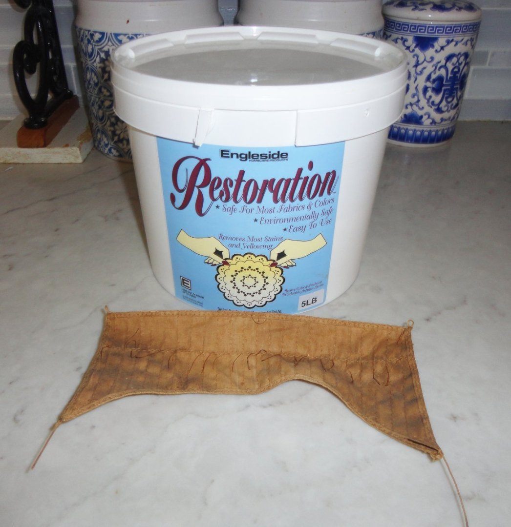
-
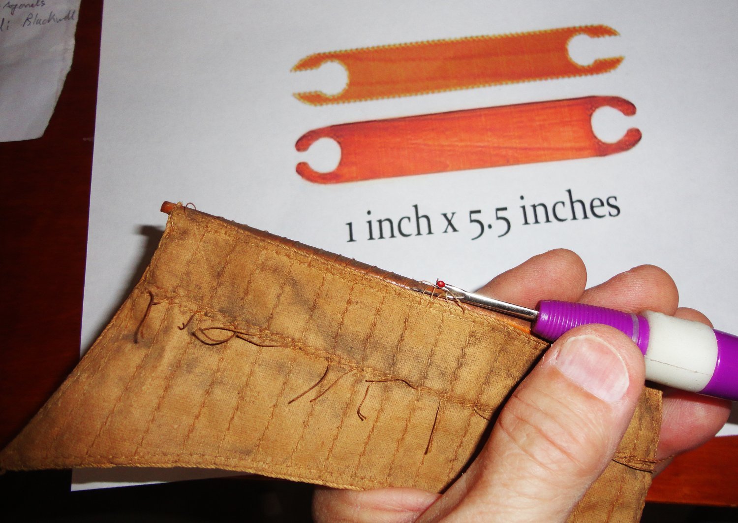
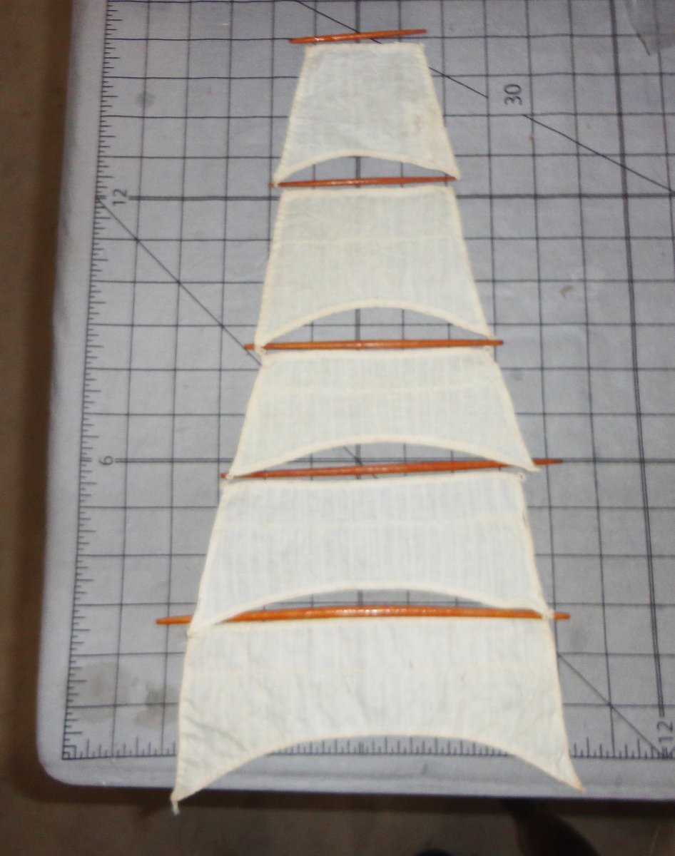
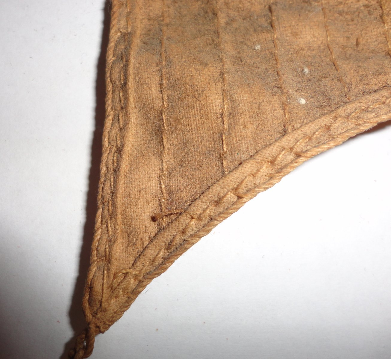
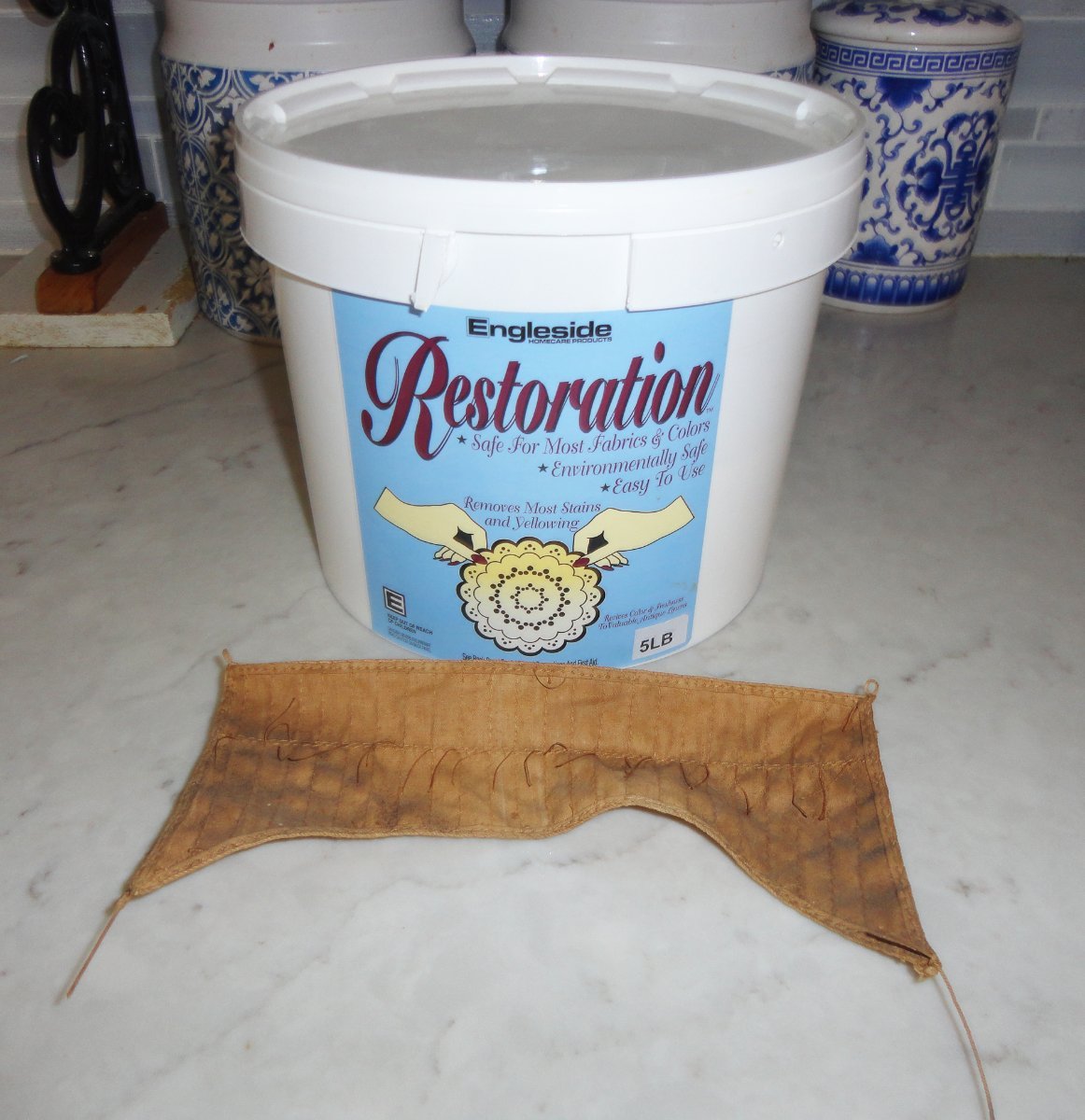
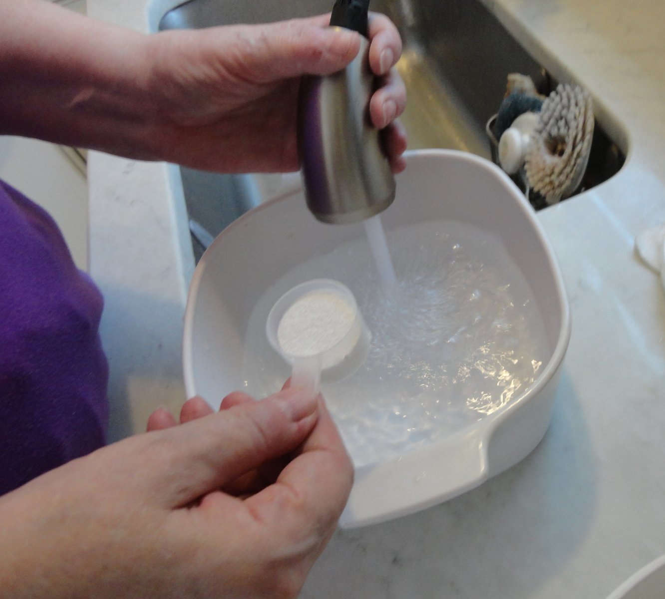
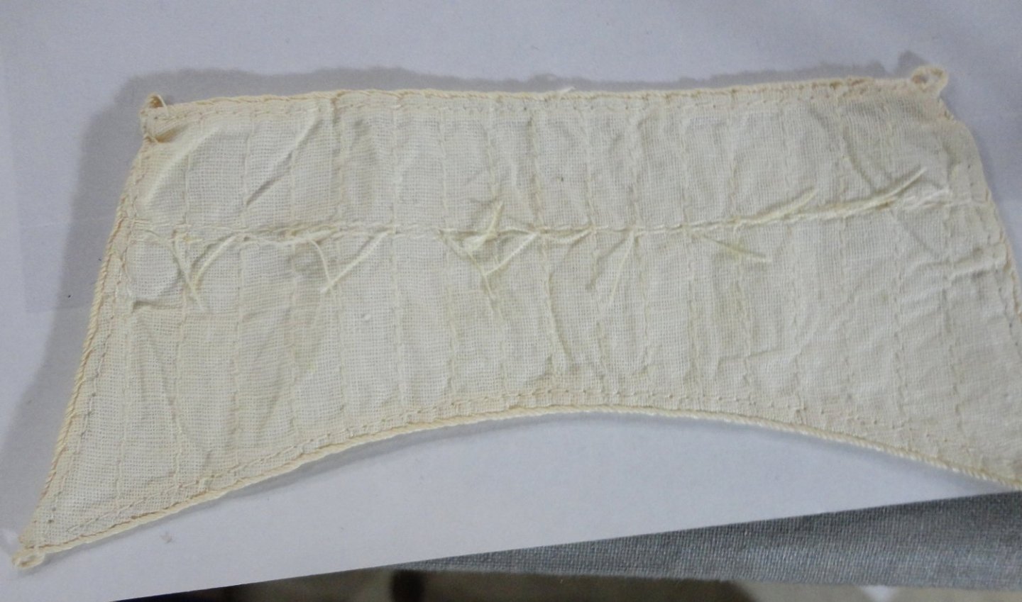
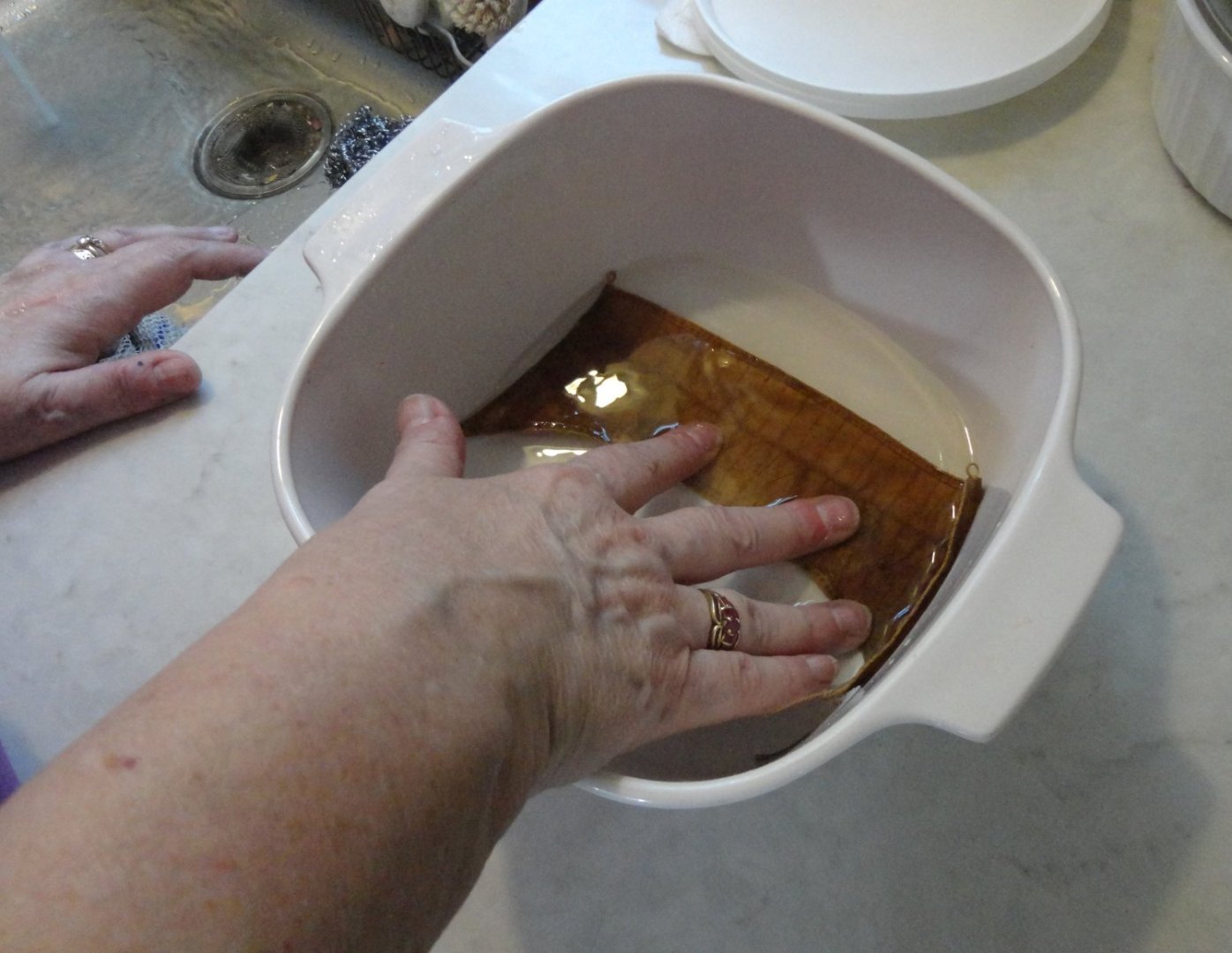
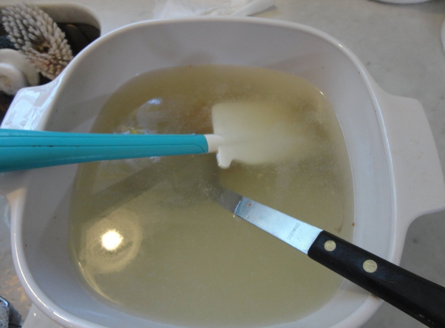
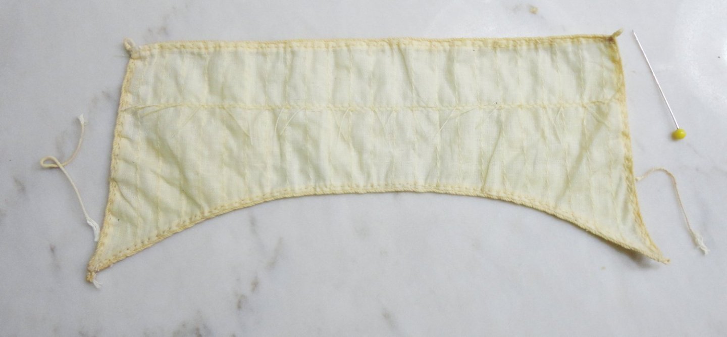
'Had to start somewhere, so the fore course was taken off the yard for examination. BTW the model's hull length of 29" is the basis of the 1:100 scale with the 244' original. There was definitely a lot of time put into the fabrication of the sails. The cotton fabric has 50 threads to the inch, but is not a 'close weave' - in that there is a gap between weft and weave threads equal to one thread width. This makes for a more supple and lighter fabric than if had been a close weave 100 count muslin. I haven't yet seen anything as suitable for this to make cloth sails out of. Below are two closer shots showing the care and workmanship in every detail. As mentioned, old style linen fishing line (true miniature rope) was had sewn around the edge of the sail using very fine thread hand sewn. The stitching imitating the joined bolts of canvas 'mimic' hand sewing due to the slightly diagonal lay of the stitching (versus the 'dead straight' sewing of most 20th century machines). I just have not seen machine stitching quite like this before (it is lockstitch, versus chain - like my Wilcox and Gibbs hatband sewer), and can't fathom which sort of machine did it ... perhaps a machine that was already quite old when these sails were made. The reefing lines are hand knotted on either side, and are of a fine thread (as is the sewing thread - possibly linen, but I'm not sure) ... and note how the ends are just cut off - but there has been virtually no un-raveling since the day it was made. ... simply uncanny ... There is some 'body' evidenced by slight 'crinkle' when bending, perhaps a little starch applied back in the day to make them look like they were catching the wind. That could explain some of the discoloration ... possibly being in an attic as well. .... makes me sigh ... A set of sails for the Mantua GF 2 retails for $150 (plus tax and shipping), but they are bulky and clumsy compared to the ones I'm working with ... with none of the fine features noted above ! And when I offered to pay cash for the model, there was a 10% discount bringing the price to $175.50 (+ 6% PA sales tax). Just the sails alone are worth way more than that ! So the Admiral gave me a tutorial for breathing new life in the sails. The product name is clearly seen on the container, and consists of sodium percarbonate and sodium carbonate ... nothing else. Now commercial products such as Oxyclean have these ingredients too, but the ALSO have other 'proprietary' stuff like surfactants, detergents, emollients, etc. Museums don't want this 'extra' stuff, because 'less is more' and one has to know exactly what one is using on antiques. There is a series of reactions where dilute hydrogen peroxide is generated, and then produces free oxygen - carrying away years of dirt and discoloration in the process. Plant based fibers become naturally acidic over time, and the alkalinity of washing soda neutralizes this ... and actually needs 3 distilled water rinses to carry away excess alkalinity to bring the Ph to near neutral. In theory, one should use distilled water throughout the process, but non-hard city water (or bottled water) is OK for all but the final rinses, which are dome with distilled water (and NOT the kind that say 'minerals added' for taste ... this is not for drinking, but the mineral free distilled water used for steam irons is required for the final rinses). The first step is to thoroughly wet in hot tap water, and we could see the water becoming discolored almost immediately. Then hot tap water in a 2 quart Corning (or Corel or equivalent) cooking pot (a glass bowl would do, but if metal - only stainless steel) - the temp is what our water heater is set for, something like 110 degrees, and add a scoop (or heaping tablespoon) of product. Stir to dissolve before placing the item in with either stainless steel of rubber spatulas to keep it under the surface. Note that there is some effervescence in the pot. The soak time was about 15 - 20 minutes, then I repeated the soak in fresh mixture. Each time, the sail became less discolored. For the THIRD soak, I heated the water in the pot on the range to about 160 degrees F before adding the Restoration product. The higher heat is needed to assure that any added starch comes out of the cloth. The product dissolved quite rapidly and the effervescence commenced almost immediately and with more vigor. I let the sail stay in for 10 -15 minutes - and I saw that is was mostly clean. I did not want to over treat, and very often, there is still just a little off-whiteness left on old cottons and linens (but I'm told that with enough treatments, a virtual white is possible ... I did not want to do this). BTW, the spa test strips used on the solution showed it to be strongly alkaline. Then I did 3 rinses in DISTILLED WATER, and retested with spa strips to show that the Ph was now within the 7.2 - 7.6 range. This is good, as over time it will inhibit the accumulation of acid over several decades. (Protein based fibers - silk and wool - have their own problems, and require different cleaning methods.) The still-wet, rinsed sail is shown below, and the difference from the initial state is stunning. (When it dried it looked just the way I'd hoped it would turn out. Fair dinkum, mates !


-
My brother got my dad's old fashioned dental drill machine, with arm segments and a long belt drive. Having a 90 degree drill head was a boon in mnay tight modeling situations.
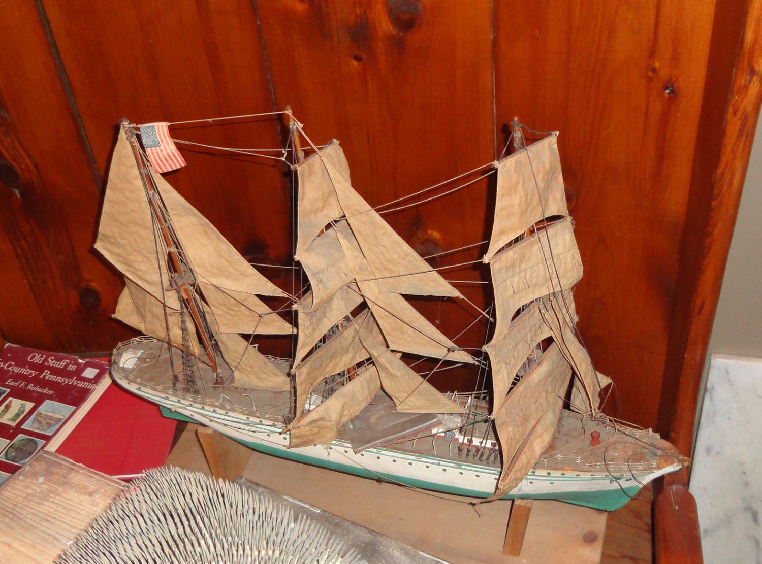
-
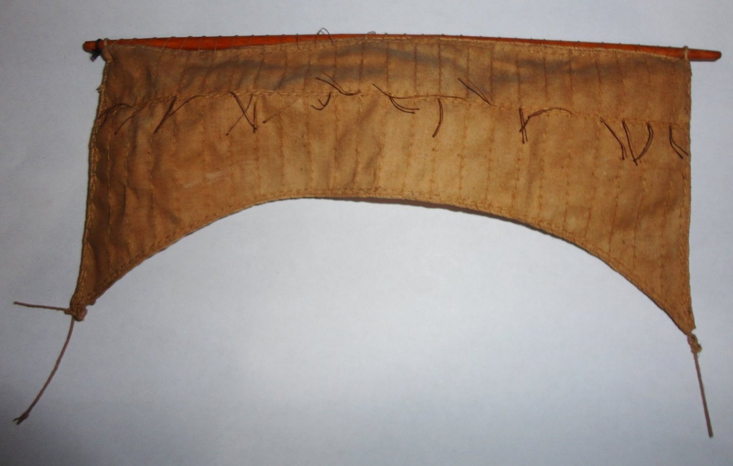
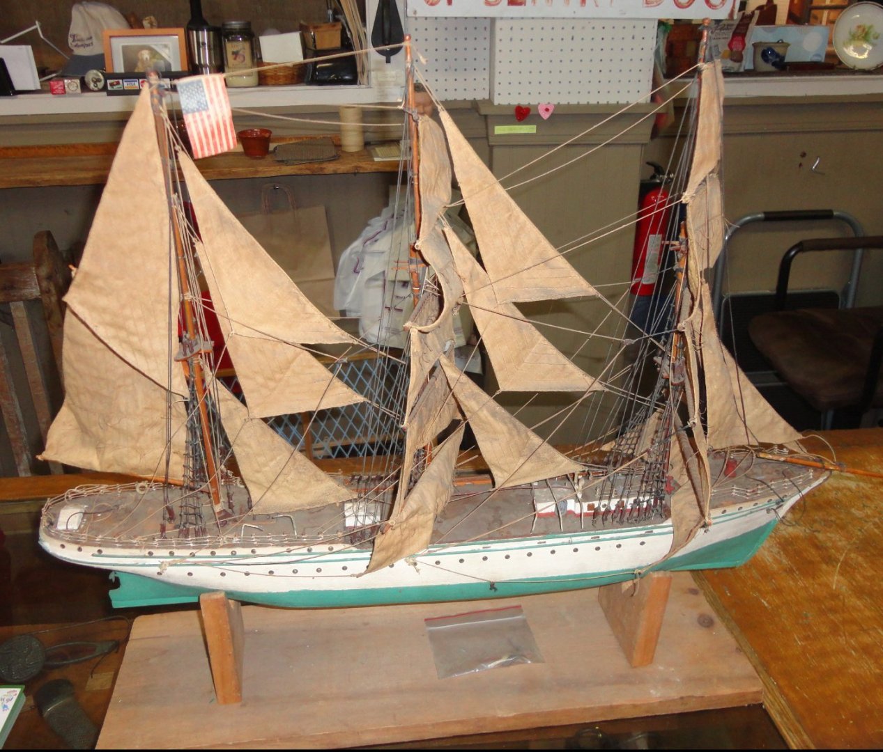
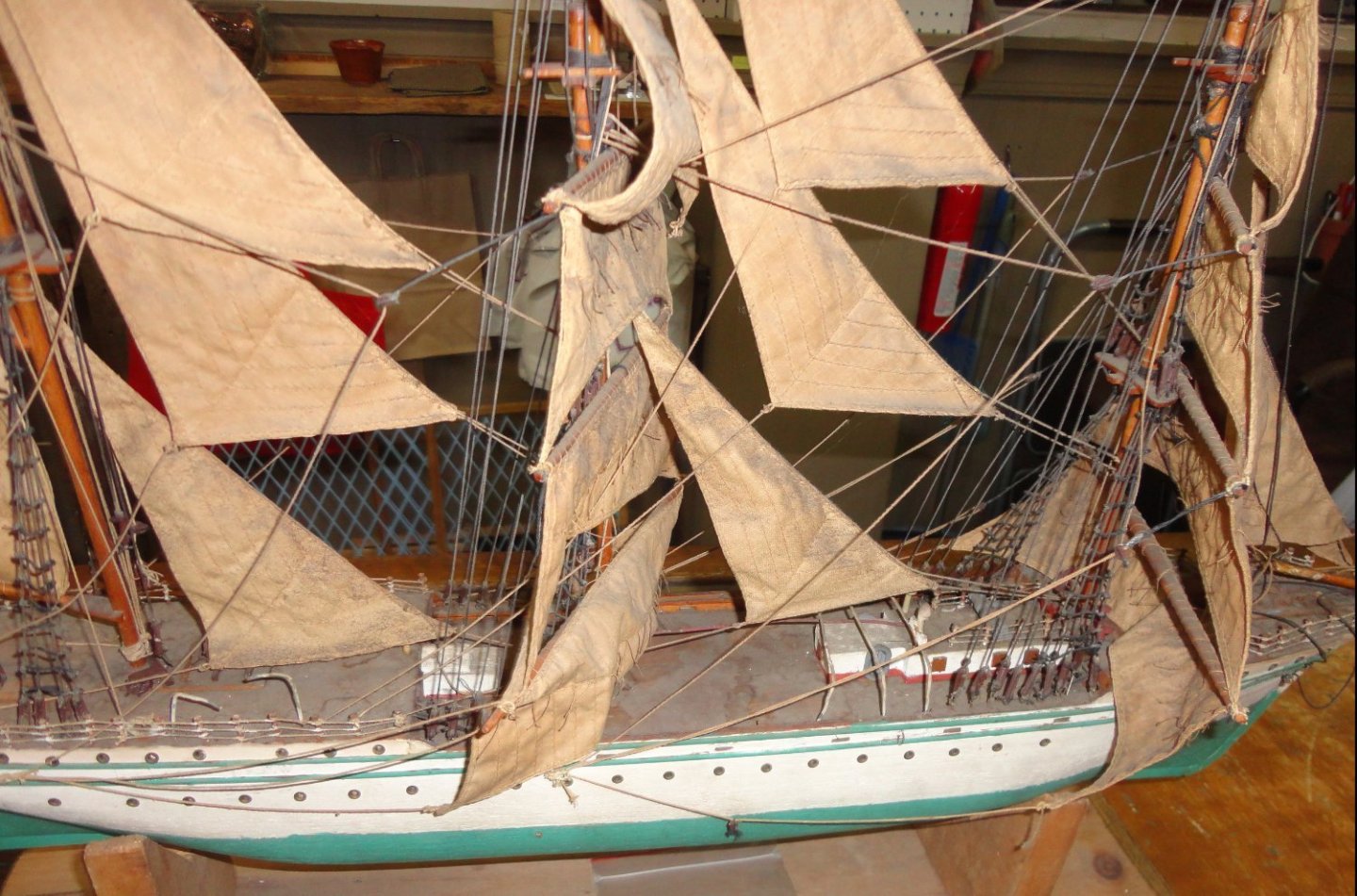
'Happened to be escorting the Admiral on an antiquing expedition July 2nd, and spied among a lot of old things, a dusty old ship model that (for all I knew) may or may not have been of a particular ship ... but despite its aged appearance had been put together with some care, and had at least one 'repair' at some point. I wasn't able to spend too much time at that berth, so continued as pilot (and purser) for the journey. Besides, I didn't want to commit to $195 for an unidentified vessel. By mere coincidence, there happened to be a post on MSW later that day on a clipper named Gorch Fock ... Lo and behold, it was the ship I'd perused earlier that day while antiquing. Some quick research was done to find that an original of a German school ship launched in 1933 (ordered and mostly built in1932, before you-know who became Chancellor), ands surrendered at the end of WW 2 ... ultimately to be reacquired decades later. The Gorch Fock 2 of 1958 is still a training ship (an improved version of the original with a number of differences), while the original is now a museum ship. I couldn't then get the idea out of my mind that I should go back to rescue the model for study and restoration - at least to revisit and inspect it more closely than I was able to do on the first go around. An appeal to the Admiral (who had just acquired some choice items on said trip) brought acquiescence, so drove the gig back alone on the 3rd. to check it out. A photo 'in situ' is below: It was placed on the store counter for a better examination, and it was a solid-hull, scratch built affair other than for some cast deck fittings that were available at the time of construction. The aging, amount of dust and coloring on the sails suggested a 50 -70 year history. With careful cleaning and a few repairs - perhaps replacement of the nails used as rail stanchions - the hull would be ready for re-rigging - and I knew that the Admiral has some techniques that could breath life into old, yellowed fabric, as she has done textile conservation before on antique garments in her collection. The object of the exercise, aside from respecting the unknown builder, would be to finally to get some experience rigging a clipper (something I'd like to build in the future, but the rigging of which has always seemed daunting). There are definite features that point to this being the original Gorch Fock: the lack of an Eagle figurehead that the GF 2 has; the green lines running full length that are seen in a 1930s photo - whereas on the second version (and also how the original is now painted) the lower line is only seen near the bow and stern with white in between - most likely because there is no 'rub rail' amid ships, but ribbing does stand proud from the hull near the ends; the lack of a largish oblong engine funnel - the original had a narrower round funnel, which appears to be among a few things broken-off/missing on this example. The age of the vintage model appears to predate the GF 2 anyway, and after the GF 2 was launched Mantua came out with a plank-on-frame model kit. Now this will make three projects to 'juggle' going forward - with me hopping from one to another, but then I was always a 'browser' (or grazer). I'll add 3 closer shots bow to stern as it now sits. Perhaps 'tough sledding in July', but this model surely meant something to somebody's dad ... and the sails appear to be finely made with hand sewn edge rope that looks like 'Old Cuttyhunk' linen fishing line (used by 'old time' ship makers in the 30's, 40's and 50's - and there are reefing lines as well. We shall see.


-
I'll quote from the 'Classic Ships' Cutty Sark by Noel Hackney (Airfix - their CS was small in scale - abt. 1:170 - and only a skilled miniaturist has the ability to do what the book lays out in that scale ... then again, there have been rare artisans throughout history that have executed incredible works of the smallest proportions in areas as diverse as jewelry, micro mosaics, watchmaking, micro-carving ... and my guess that no more than one in ten thousand have that level of accomplishment - at 1:96 things are much more manageable for the 'rest of us'). "The most effective way to build an accurate model is to do it in the same order as that used by the original builders. This is the basis of the system detailed in this book, although some stages are changed from their correct order for ease of building." That the book may seem puzzling until studied at length (and a fair knowledge of relevant ship and rigging components helps), realizing that three 'versions' of rigging are 'compressed' (and mixed with a tricky 'coding' system) into a slim volume: one ship that is simplified; one with detail but w/o sails (harbor rig) and one in full sail. As this relates to your project, his method is designed to limit deformations of bendable masts and spars - which if plastic, bend more than wood. He recommends mounting the first sections of masts plus their respective shrouds and forestays ... first, then work upwards level by level - balancing the forces as one goes. The shrouds are place and adjusted in pairs (left and right) to minimize pulling to either side - and the forestays counteract rearward pull by the shrouds - and further up, the backstays. (Note that many builders wait until near the end to bother with the ratlines, that can otherwise make all the other rigging more difficult. Shrouds w/o ratlines permit tools to be place through them to manipulate other stuff. There is another 'school of thought' whereby each mast is made off model (preliminarily rigging the yards as well) before placement ... and this can work well as long as the shrouds and stays (fore and back) are done from the bottom up to balance forces exerted by the rigging. 'Don't know if your masts are glued in (some don't use glue at all inch the lower shrouds will keep them from ever popping out), but any bending can likely be adjusted with fore stays. Seems the masts have a rearward rake anyway (by a few degrees_ and as long as all the masts seem 'to the eye' to 'line up' (at whatever angle) all should be well. And then, a photo can exaggerate from how a model looks in person.
- 89 replies
-
- 3
-

-
-
- Cutty Sark
- Revell
- (and 2 more)
-
Sorry, mate ... 'never meant to cause a stir (I'll have to study history more) or get anyone's knickers in a twist. So I've edited the post to simply say that English Kings maintained a claim to the French Crown. Hmmmm, my mom comes from a long line of Brandons descending form the John Brandon who married Henry VIII's sister. So I suppose I might claim to be in line for the English Crown, although I dare say that there are a LOT of people in the queue ahead of me. It was also said, "When Adam delved and Eve span, who was then a Gentleman?"
- 45 replies
-
- 1
-
-
- Great Henry
- Henry Grace a Dieu
- (and 1 more)
-
Yeah, I see the phenomenon of the cannon scale ... and that as a result they aim slightly down. On one project I was able to 'raise' the gunport locations on some (with the associated bodging that had to happen) but on other gun positions it was not possible to raise the gun port height (as appears to be the case on the Harriet). My solution for those cannon was to abrade the wheel bottoms enough to lower the carriage while simultaneously deepening the notches in the carriage that receive the trunions (thus lowering the barrel into the carriage more). I figured the 'sleight of hand' for those guns would largely go unnoticed .. or if noticed on close inspection would be less noticeable than a 'drooping gun' (I hate it when that happens) would be during less-close inspection. I've learned through experience that one should never presume that the kit designer(s) have worked everything out perfectly ... or have even done the extensive research one would hope was done. Yet it isn't possible to mentally 'pre-build' everything, thus will come the revelation at some point in the process that things are not ending up exactly as they should. That's when you have to set the plans/instructions aside and think 'outside the box'. Now giving you square stock (which must even be cut out) to make round masts (and yards too?) just isn't first rate, mate ... and basswood, no less. I think you can get better round stock in various sizes of better woods (oak, maple, walnut, etc.) in many hobby stores and even in 'big box' hardware stores. There are a number of ways to taper round stock as needed shown in several threads on MSW. You are doing great job on the build all around !
- 25 replies
-
- 4
-
-
- Harriet Lane
- Model Shipways
- (and 1 more)
-
The above discussion on ways to have the anchors stowed are very helpful, as I'll eventually have to deal with the issue on my presently side-lined project.
-
You have an excellent model ... and what a coincidence that I should see your post today. The Admiral wanted to revisit three antique shops we'd seen with friends a few years ago (an hours drive away), and she saw a three items to collect - then I spied a forlorn clipper model (approximately as big as a 1:96 Cutty Sark) in a back room with yellowed sails, sagging rigging and a dust laden deck (the estimated age is 50 - 70 years). I wondered if someone had tried to do a Thermopylae in her final years as a barque with a white hull - yet there were small port holes going down the side, and a green rub rail and green bottom from the water line down. Some 'air scoops' on deck were noticed and a small propeller ahead of a missing rudder, so I could not fathom it to be the Thermie. And of course there would be repair/conservation work to do, so I passed on the mystery ship priced at $195. Yet the clear photos in your postings appear to be a pretty close 'match' to what I saw today. Mention was made to the Admiral about seeing a model that could be 'spruced up' (completely cleaned and re-rigged actually) and I may be able to get a green light on going back before too long on a rescue mission ... especially since some major projects have been cleared from the duty roster so far this summer. I believe the hull and much of the deck furnishings are sound, with careful cleaning being the main need - plus a few loosened items secured, and the railing need re-doing (and the broken bowsprit fixed). The discolored sails may be remedied by an Admiralty trick to remove yellowing from antique lace and cotton fabric - with a trade name of 'Restoration'. So the main task time-wise would be re-rigging more accurately - which might be just the practice I need in this area. Having a pre-made wooden hull (and not a bad one, at that) provides a short cut to the 'other' half of doing a complete model.
-
I found that Artesania Latina sells various kit replacement parts, and there were three sizes of gunport surrounds w/lids; 7mm, 9mm and 13mm. The 13mm are not the ones I have from the San Juan (different and more detailed castings), but it is unclear WHICH dimension of the remainder is being cited; the size inside the surround (between liners), the lid size or the O.D. of the surround. So I ordered 2 sets (4 ports ea.) of the 7mm and 2 sets (3 ports ea.) of the 9mm. - and they weren't expensive. One of sizes should match what I have on hand. There was a problem ordering from Spain by credit card, but PayPal worked alright. The Admiral noted that the same was true when she's ordered needlework supplies from overseas - so PayPal is always used, and credit cards are for domestic ordering.
- 45 replies
-
- 2
-
-
- Great Henry
- Henry Grace a Dieu
- (and 1 more)
-
Ditto for me, and it didn't help that the commode in the en-suite decided to stop working yesterday. 'Seems not just the fill mechanism ceased to work, but 11 years of continuous use by all hands corroded bolts, degraded washers and seals to the point of impending disaster if not completely replaced. In for a penny, in for a pound ... and the Admiral insisted that full functionality be restored at once. So today turned into one of those 'dirty jobs' aboard ship - with a trip for components and hardware, a search for tools and a complete clean-out of the head. Now if only I could 'restore' full functionality to my pleasure craft ...
-
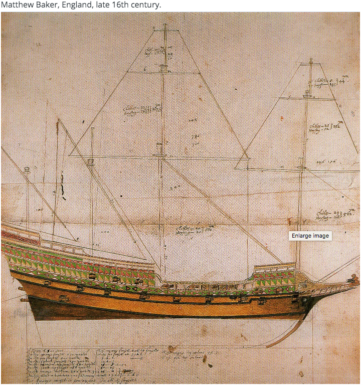
There is a mnemonic for Henry's wives: Divorced, beheaded, died - divorced, beheaded, survived. Anyway, the discussions of scale here and elsewhere had me consider the difference between knowing the exact hull length of a ship (therefore being able to calculate the scale of its model) versus when one does not know the 'true' hull length, and is using an approximation. My estimation of 165' on the GH hull was based on the estimations of tonnage (and there are several published) difference between the MR and GH. We know the hull length of the MR sue to what has been recovered (and that much is remarkable for such an old ship). So my stated scale of the GH being developed is based on an approximated length, and another builder might have settled on a different hull length before drawings are made for another model of the same ship. The key is that both models are using the MR lines as a basis (and that is both reasonable and logical) they will have about the same hull proportions regardless of model size. Now if by some miracle as much of the GH were found as was found for the MR, we'd know the actual hull length of the GH ... and from that 're-calculate' the nominal scale of the models already built. Thus its not the estimated scale that matters, but the proportions of the model. In other words, does it 'look' the way it should (with allowances for construction decisions/appearances made for some features subject to interpretation). The GH lines I've developed are not 'exactly' those of the MR, since the larger ship does not quite 'scale-up' the same and still be practical and seaworthy. But they are still close enough the the GH is 'big brother' to his sister MR. The stern castle as depicted on the Anthony Roll flows right out of the hull form. There have been (and shall yet be) some decisions made on the appearance of the fore castle, with the A.R. as an inspiration. The GH is getting my attention now because of its novelty, and also that the work done already on the Vasa was mostly aimed at trying to correct the deficiencies inherited from an old kit built too far to go backwards very much. Yet when further work is eventually done, it will have an adequate 'stand off' impression of the original - recognizable to anyone familiar with the subject. Fortunate is the builder with a contemporary kit (yes, there ARE a great many carved figures on the original) and, of course, many photos of the original in the state of restoration practical as she sits. A project like the Golden Hind (and there have been many interpretations of it) presents far greater challenges, given the lack of naval archeology on that ship and the lack of contemporary specific artwork for the Golden Hind. I've recently posted some considerations for omitting a "Captain's walk" on the Hind, since the builder's excellent hull construction had not yet reached a commitment point for that feature. Decoration of the exterior is completely 'up in the air' for any version of Drake's flagship, whereas there is something to go on for the painting of the Great Harry based on the Anthony Roll. Ok, maybe I'll try an 'pimp it' a bit here and there ... as the Sergal kit does have small brass fleur-de-lis that could go on open gun ports (like the lion heads on the Vasa gun ports). English Kings of old maintained a claim on the French Crown as seen on Royal heraldry ... and the fleur-de-lis on some of the shields seen on the 'embarkation' painting.
- 45 replies
-
- 4
-
-
- Great Henry
- Henry Grace a Dieu
- (and 1 more)
-
Something I've done on occasion to mate a smaller object to a larger surface (flat or not too curved) is to place a piece of sandpaper (the kind with a 'grippy' back so it resists sliding) down and then run the piece to be mated back and forth with relatively short strokes (and not too much pressure). That way the places that need to be abraded are reduced until the two surfaces are a match.
- 144 replies
-
- 3
-
-
- Harriet Lane
- Model Shipways
- (and 1 more)
-
Nice recoveries ! Necessity is the mother of invention. Hmmmm, I even remember a group called the 'Mothers of Invention'.
- 144 replies
-
- 3
-
-
-
- Harriet Lane
- Model Shipways
- (and 1 more)
-
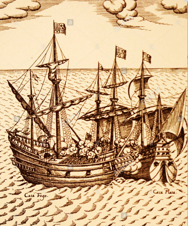
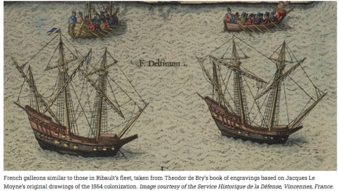
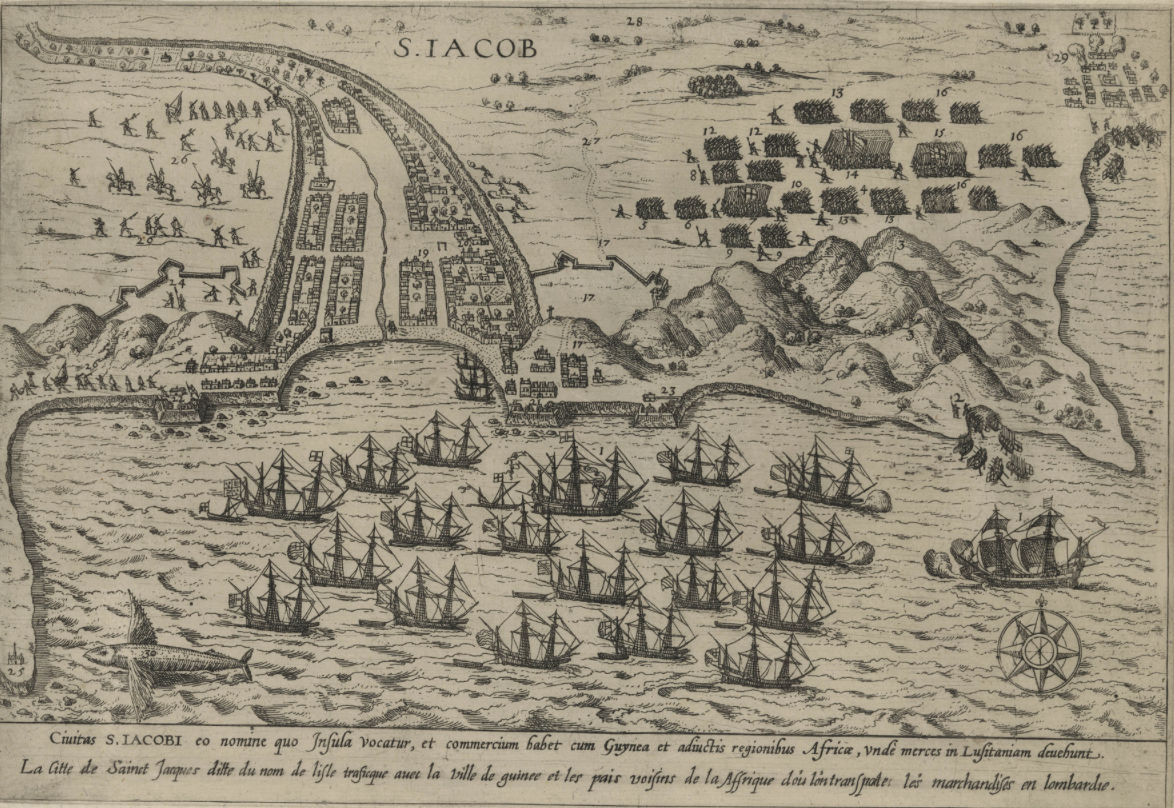
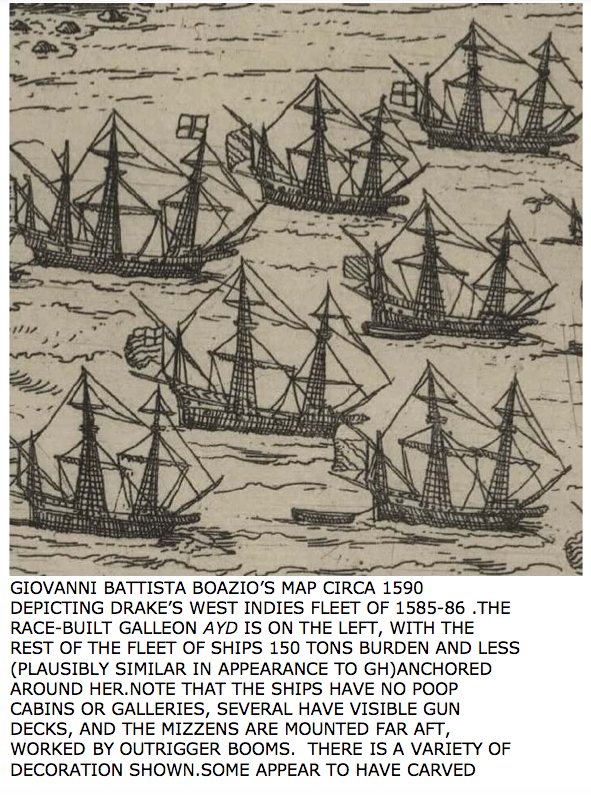
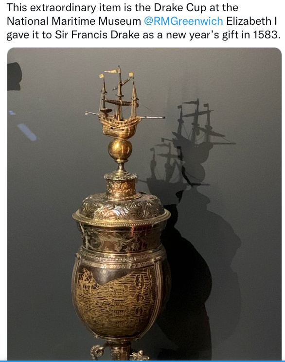
It is fascinating to see your progress, and is much the same way I've gone about creating a framework to plank around. The 'guest' of Drake from the Caribbean to the West coast of Mexico was the Portuguese navigator DaSilva, and his testimony to the authorities and the Inquisition concerning Drake's ship were consistent - noting much about the ship (including its 'French' design - ergo 'race built') and citing 14 guns available for broadsides (7 per side) plus 4 "at the bows", taken to mean the traditional 2 straight astern and two others (exact location not specified) ... perhaps either near the bows on the gun deck (angling forward) or in the forecastle under its weather deck. There is room for interpretation here and the accounts make for interesting reading. One thing that I've pondered is the prevalence of 'Captains walks' on repro GH ships and most model kits include them. Perhaps the contemporary artwork (often of Spanish or Italian galleons) showing such walkways has influenced more modern painters and builders to include them on the GH. Yet there a number of contemporary depictions relevant to the specific time and place of the GH that do not have stern-surrounding walkways. One shows the GH capturing the Caga Fuego (the formal Spanish name is longer, and the 'nickname' has spelling variations meaning something like 'firing poop'). The Spanish ship has a walkway, but not the English vessel. Below are French galleons of the period - perhaps just before 'razee' (razored, ergo 'race') of the topmost level astern. Below is a panorama of Drakes Caribbean fleet - and not a Captain's walk to be seen. A detail from the above drawing: Also: Then there is the 'Drake Cup' commissioned by Q. Elizabeth - the bowl made of a coconut given to her by Drake which she had engraved with an image of the GH being towed by native canoes in the East Indies, set in silver and with a silver top bearing a tiny 3D GH. The GH was in sad shape when it limped home to England after the circumnavigation, but no doubt was re-habed and redecorated (perhaps on the Deptford creek while a permanent mooring was built on the Thames) - and so models of the GH at any scale that are brightly painted with "ER" on the stern and depictions of a golden hind (and perhaps a 3D hind at the bow) are likely how the ship appeared docked on the Thames for the formal ceremonies with the Queen bestowing great honors on Drake aboard the GH. I suppose that a walkway could possibly have been added after the fact - just for show - but the engraving on the cup and the model atop the lid do not have walkways. 'Just food for thought (and I've thought about it myself). The GH may be considered the first 'maritime museum' (of sorts) - intended to be preserved in perpetuity (the Queens stated intention). Yet much of the masting, spars and usable materials (guns surely included) were removed not too long after the ceremonies on the Thames, as a wooden roof was said to have been built supported on mere poles. Said roof was subject to rot, and there are accounts of various uses of the GH as she slowly deteriorated - requiring filling the mooring all round her with packed earth after a berm was built to enclose her. Before a few pieces of usable wood were removed for making of furniture, what was left of the ship at the weather deck was knocked inside and the hull filled with soil ... a burial - perhaps for future marine archeologists? Subsequent site usage likely disturbed much of what may have existed on the wreck above the water line, but molds of the hull may yet be preserved in the ground that could give the length, beam and lines of this historic ship ...
-
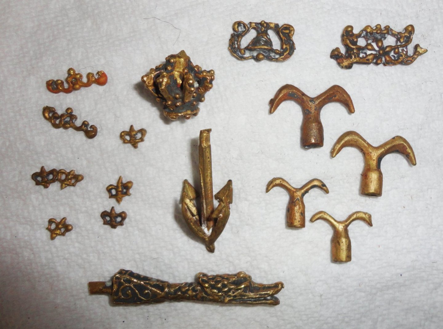
The castings were unwrapped for a picture, and the bits of white plaster on them appears to be left over from the matrix of 'lost wax' casting of the brass alloy. They will clean up nicely. The size of the bits appear OK when held next to the framework I have so far. Now as for the curved inner face of the fore castle, we've all seen the distinct forecastle curvature on period artwork of earlier carracks, as well as moderate curvature on many ships around the same time as the GH - and a few that look flat. Since I've decided to favor the A.R. depiction for the model, the amount of curve employed may be a reasonable 'interpretation'. I've read-up on Henry (the eighth of that name) and his reign ... seems he was VERY security conscious, as many Kings were. He kept a secure sleeping chamber equipped with a door lock only he had a key to, so he'd lock it from the inside and guards were posted outside the door. When traveling on a 'progress', the King would have the largest room in whatever noble's mansion he was to stay at. A special locking mechanism had to be installed ahead of time that only Henry would have the key to. So I imagine that when the GH was ever readied for use by Henry, the back part of the officers' deck in the stern castle was partitioned off with linenfold paneling as the private chamber or 'closet' (with lock). There was probably a chamber ahead of that for the noblemen who served the King's person, then another area where the King might confer with the Captain, envoys, etc. There is much interior detail that survived on the Vasa (seen on links in another MSW thread) where the interior had a 'forced perspective' making the the more important person seem larger to anyone positioned at the forward end of the area. 'Wouldn't surprise me if there was something like this inside the GH - and no expense would have been spared for the King's comfort and grandeur.
- 45 replies
-
- 3
-
-
- Great Henry
- Henry Grace a Dieu
- (and 1 more)