Snug Harbor Johnny
-
Posts
1,501 -
Joined
-
Last visited
Content Type
Profiles
Forums
Gallery
Events
Everything posted by Snug Harbor Johnny
-
 A fair point to be sure, Ross ... there ARE different qualities of contact cement. And yes, the cement needs to be almost completely dry on both surfaces before pressing together - and one chance is all one gets for correct positioning. There is a step in the gluing of counter tops following the positioning - and said positioning is often done with the formica overlapping the countertop a little - so the 'exact' placement is not as critical since the excess will be trimmed off with a special router bit designed for this work. That important 'next step' after positioning is a thorough rolling of the surface with a heavy roller having extra force applied by the assembler from above. Note also that when the pieces are joined that one edge is placed first (with the thin top flexed a bit to make it curve), then the remainder 'rolled' down onto the surface to prevent any air getting trapped in the 'sandwich'. The heavy rolling is also may drive out air near the edges, and one can hear a popping sound when air so compressed (and driven to an edge) escapes. I witness all of the above myself. After the top is in place and trimmed, the sides are applied - and they are most often a standard thickness to go onto a specific substrate. I will agree that I've not seen a failure (de-lamination) of a top piece, but have seen several edge failures - and one in my own kitchen after 25 years (we are not the original owners, and I've since remodeled the entire kitchen myself - except quartz countertops made and installed by professionals). That is why I'm not so concerned with contact cement for flat (or near flat) deck planks on a model, but cautious about curved hull planking with that method ... since I'm thinking of a time frame a lot longer than the first 10 years. The cheapest (and least desirable) contact cement would be artists' "rubber cement" - or perhaps even worse ... "spray mount". These products were intended for temporary 'paste ups' back in the day, and have been largely superseded by modern computer art. Trade-name 'Weldwood' is likely better and easily found in bottles with a brush built into the cap. There may be better grades under other trade names.
 -
Hmmmm, I suppose it would be too much to try and have the oars-persons 'feather' the blades on the back stroke. The full size oars are rather heavy and its enough having the crew pull together (at speed). The video reminds me of the times I was a rower on a small Viking Knarr (5 oars per side), as the wind often did not cooperate. While resting during one outing (true story), the steersman said, "I have good news and bad news. The good news: a round of mead for all the crew. The bad news: Captain want to waterski."
- 536 replies
-
- 3
-

-
- Quadrireme
- radio
- (and 1 more)
-
'Love the way you're proceeding with your project. 'Much the same way I often work ... cut to fit, bend to suit, and trial fit things - especially good for insuring that the cannon barrels will look reasonably straight and orderly when run-out.
-
'Have to agree with Allan, in that rubber cement just won't stand the 'test of time'. Sure, it can be an immediate shortcut ... but in a decade or two things glued with it can de-bond. 'Can't recon why OcCre would promote this method, other than for ease of build. With luck, horizontal surfaces will have gravity to keep them in place - as well as other stuff put on top like deck houses, fife rails (which should be well-pinned to thicker substrate previously glued underneath ... they don't tell you that), stanchions/bulwarks, a forecastle, etc. As for the hull, pre-bent planks just being fixed in position with contact cement that will be painted over may get 'reinforced' in shape by a coat or two of over painting. Additional items pinned or otherwise affixed over exterior planking (like channels & chainplate) can also act as bracing.
-
Occam's Razor says that the simplest explanation is most likely right (versus complicated ones) ... so perhaps a corollary for model builders is that the easiest method to get an outcome should be preferred (over more difficult ones).
-
Now there is a line drawing said (in several sources) to be after a Hans Holbein the Younger drawing. This line drawing is identical to a ship in the embarkation painting. Holbein did not paint the embarkation (not at all his style, as he was primarily a portrait artist), so if he did a ship drawing, it was because he saw the pre-existing painting. Holbein first went to England between 1526 and 1528 before returning to Brussels for 4 years. He might have seen the painting on the first visit, but he had not yet received patronage from King Henry - thus likely did not have access to the painting on the first visit. Holbein returned to England in 1532 under the patronage of Anne Boleyn (and soon after by the King). He remained a resident (and successful portrait painter) until his death in 1543 at the age of 45. Thus said drawing should date between 1532 and 1543, with my estimation being towards the earlier part of that range - based on the likely pre-1536 configuration of Henry's fleet.

- 45 replies
-
- 3
-

-
- Great Henry
- Henry Grace a Dieu
- (and 1 more)
-
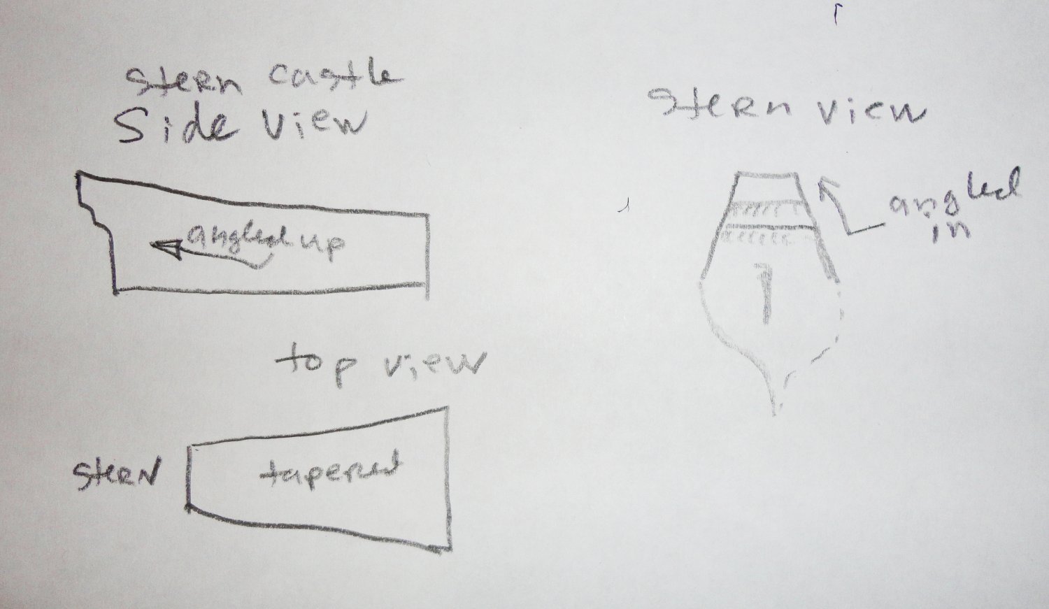
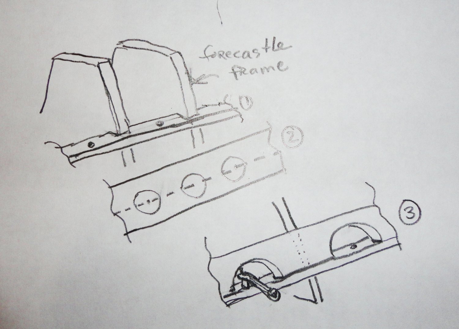
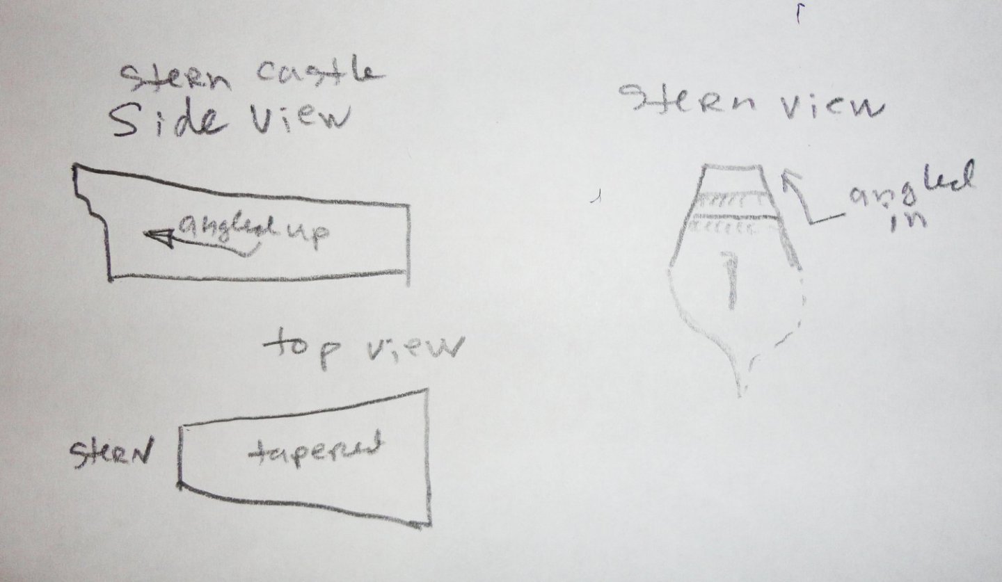
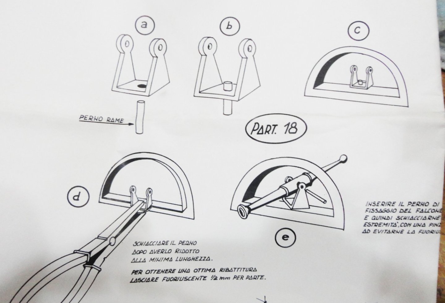
The geometry of the stern castle (and also the fore castle) is not the easiest to put-together from square-cut flat stock, as the angles become compound. I've made a sketch (and again, I'm no artist) form the usual 'orthographic' point of view, in that from the side there is a nice upward angle. From the stern the castle is angled inwards on both sides, and seen from above there is a taper going sternward. So new pieces have to have the edges angled until they fit more or less correctly. As mentioned before, the castle sub-assemblies will be removable (for now) so they can be faired by sanding, also worked on by adding gun mounts, lunettes and first planking. This will allow the hull to be turned turtle for the bottom planking ... before being set in some kind of cradle for right-side-up work. There are some nice swivel guns provided by the kit, but they are designed to be mounted in stamped brass lunettes that are a bit large for the scale I'm bashing the kit in. Also, the application of brass surrounds don't seen right (or at least they are not documented) for any of Henry's capitol ships. The image below is from a kit plan. I've given this some thought, and made a concept sketch of how I may install them. #1 is to notch the vertical frames and attach a horizontal rail across the castle frames at the level of a row of lunettes. This rail is to stand proud the thickness of the first planking. There will be pre-drilled holes for a brass pin of the swivel mount. #2 will be to mark out a strip of material (the thickness of first planking material) and note the center point of each lunette. These are drilled out with a Forstner bit (to avoid tearing), then cut down the middle (dotted line) to make matching lunette first planking for either side. #3 shows the lunette plank attached, and a swivel gun in place ... The pin can be bent over on the underside of the mounting rail prior to the addition of first planking below (to make sure nothing will come loose later), and I'll just have to work around them when the lapstrake 2nd planking is put on. Or perhaps just the swivel bases can be put in, with the guns added later from the outside. I can't decide just now.


- 45 replies
-
- 2
-
-
- Great Henry
- Henry Grace a Dieu
- (and 1 more)
-
One job in a work house (a residence of last resort for the destitute) was to pick apart old rope for the fibers. 'Guess there was always a market for inferior (thus cheaper) oakum. Note that the specification for the better stuff implies that the cheaper stuff was in use as well. Hmmm, just as there are cheaper brands of paint (one often gets one what pays for, as the cheaper ceiling paint I used once was so bad I had to paint over it with more expensive quality paint). There was a story about a painter who 'stretched' white latex paint by adding some water while painting a Church steeple. When done, there were dark clouds and lightning as a furious rainstorm washed off most of what had been applied to the steeple ... and a voice from above was heard to say, "Repaint, and thin no more !"
-
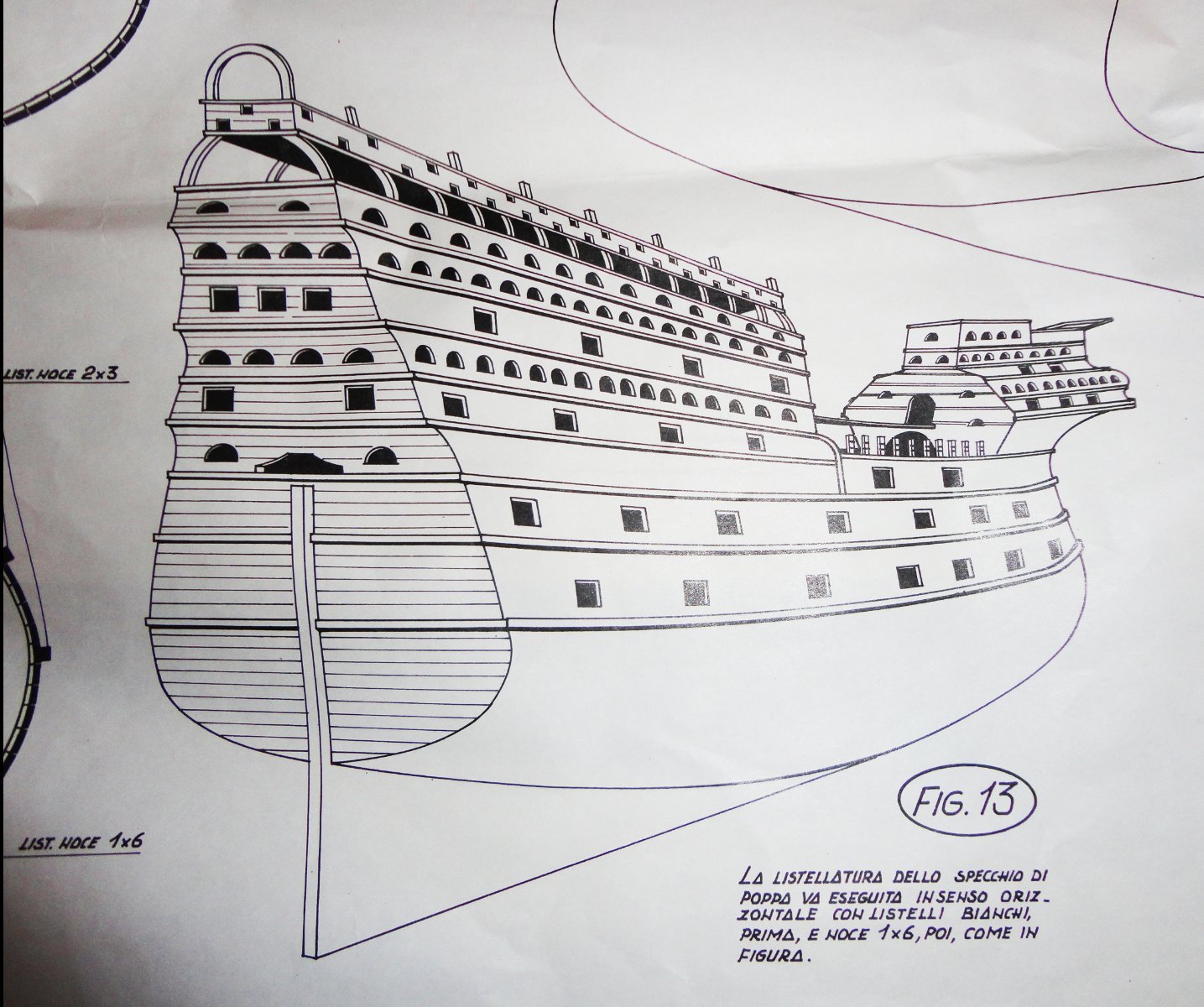
'Sorry for the snail's pace of the project, but there are so many things to do outside this time of year. I DO think about the build a lot, as things need to be done a lot differently than 'as supplied' - and this issue has been noted in earlier posts. Note the 'fantasy' look of the castles (and the inaccurate lines) in part of the plan shown below - my castles should end-up resembling those shown in the Anthony Roll. My lines are close to the Mary Rose. Thought is given for potential courses of action (and the steps in order to achieve), then other ideas are mulled over. What I may do is do forge ahead at some point and just 'go for it' - with course corrections made 'on the fly'. It is, after all, a wooden medium which can be carved, cut/sanded or added onto in various ways ... and the castle exteriors will be painted. I've ripped off and changed enough of my other project, anyway. Meanwhile, most of the frame pieces have been 'nudged' (bodged?) into a shape that seems OK when a thin, flexible spring wire is curved over the profiles in various ways - a sort of pre-faring. Then I'll have to trace each piece in full size for archival purposes.

- 45 replies
-
- 5
-
-
- Great Henry
- Henry Grace a Dieu
- (and 1 more)
-
Back in College, our history club converted a surplus U.S. Navy whaleboat (lifeboat) into a Viking Knarr, and the gunwales were of teak. They were pre-weathered and of a light to medium brown (as I recall), but being an 'oily' wood there was no noticeable deterioration. As an annual maintenance, either Teak or neatsfoot oil was rubbed on the gunwales - which turned them into a darker brown that lasted a good while. There seemed to be excellent durability even though exposed to the weather Spring thru Fall. It was taken out of the water and trailered to a storage yard for the winter, where a rainproof tarp was tied over the open hull. We took turns prying out loose caulking (which was most of it) and otherwise driving fresh oakum into the seams before applying new caulk - and in Spring a fresh coat of anti fouling paint.
-
Great point, so an alternative might be stainless steel wire pushed into a pre-drilled hole so only the head shows. That will stay bright for a long while, versus a blackened look some seek, but will be differetiable from wood tree nails to an observer. I suppose thin black plastic rod is an alternative ... if the stock is too thick to begin with, one can heat and stretch over a flame by pulling on both ends as it softens. Or (another option) is to color the end of a wooden tree nail black (whether tooth pick or something else), since only the end will show.
-
There is great detail you're doing on this build - truly inspirational. Will there be any representations of iron fastenings or tree nails?
-
I did see the HO offering of Medieval Fair figures (including modern attendees), but was confused by the term "out of stock but available to order". Of course, I've found a number of possibles at 1:72 - but they are oversized for my purposes ... unless once the frames are reasonably perfected I opt to enlarge tracing of them to build at 1:72. That would add half a foot to the project, while not that much by itself, the volume, weight and case size go up - 80% more case volume enclosed. I'll most likely get figures that can be modified - only a few would be needed for scale. Noted in the detail of the embarkment painting are the sailors on the yards with no foot ropes. Not having foot ropes, jackstays, or belaying pins needed for these ships does simplify the rigging somewhat from, say, an extreme clipper. Parrels retain the yards and halyards raise/lower them. Add lifts and braces and not much more (other than shrouds with ratlines plus forestays for each mast) is needed for a ship in port with no sails mounted on the yards. There are far fewer yards to deal with as well, compared to later periods. As for that painting, I'm not convinced of a date as late as 1544-5. This was only a year before Henry died, ergo is more likely a "latest possible date" - just as the finding of a dated coin in an archeological dig makes for an "earliest possible date". But early coins circulated for quite a long time. True, all the ships seem to be 'clones' of each other (and have certain inaccuracies), but the absence of top gallants and the similarities to the 'wedding' painting discussed earlier (most likely painted not too many years after the wedding in the 1520s) hint at the 1520s. If one is going to 'blow one's horn' over an accomplishment, one is likely to do so relatively soon after that accomplishment. As we know, the peace negotiated prior to the Field of Cloth of Gold 'summit meeting' (likely more of a 'face saving' move by Francis I and a cost avoidance by Henry VIII due to the Emperor's withdrawal of military support) did not last for very long. And lavish wedding gifts tend not to be given decades after the fact. Ergo I think it likely that both paintings most likely date prior to 1536. That notwithstanding, if a pre-1536 version of the HGaD was to be considered, the presence of specific shield heraldry seems like a PITA to reproduce in a small size and still look nice. Hmmm, I suppose an artist skilled in computer art (like my Admiral) could make nice versions that could be reduced and color printed on paper to mount on small wooden shields - then brushed with clear shellac to seal. The effect might simulate the heraldry painted on flexible leather before being applied to wooden shields - as the shields are exposed to the elements and paint will peel/weather off wood before long as the wood swells and shrinks under varying conditions, whereas the painted leather would hold up better. I'll have to make some shields anyway - at least ones bearing the Cross of St. George ... "Once more, my friends, unto the breach ! God for Harry, England and St. George ! " Hmmmm, 'Reminds me of a story about a grieving woman who had been co-owner of a night spot with her late husband. She'd gained so much weight in her grief that a strange diet was tried - one that required the dieter to be locked in an apartment for a month with only 2,000 pounds of bacon to eat. The idea being that one would be so sick of it that weight loss would be the result. A month later, upon emerging visibly lighter, her 3rd best friend Richard declared, "Now is the widow of our discotheque made glorious thinner by a ton of pork ! "
- 45 replies
-
- 3
-
-
- Great Henry
- Henry Grace a Dieu
- (and 1 more)
-
'Found an interesting image and I thought I'd bring it to your attention. It shows the upper topsail let down ahead of the lower topsail (which, if at sea under growing winds, would block the breeze from the upper sail so lowered - and it could be taken in easier via bunt and leech lines). 'Looks like one of the the royals is similarly dispositioned. This is yet another way to depict a model with sails (versus bare yards), in this case probably drying them in port - another actual scenario seen in this colorized photo.

-
Kevin, That's one reason why my building takes sooooo long, in that I'm trying to think ahead many moves (as in Chess) as to what has to be done and the order things should be done in ... and what has to be changed, then how will that change affect other stuff ... and so on. But I always miss SOMETHING - we all do. So I'll end up doing the 'next best thing' to get past the issue and forget about it. I used to be a Manufacturing/Industrial Engineer (before a lot of industry was world-sourced), and was at a conference for problem solving. One attendees explained a particularly knotty factory problem to the moderator and asked what was the best thing he could do. The moderator said, without hesitation, that the best thing he could do was to marry a rich woman and get the heck out of the factory. Then he said the group could start brainstorming the 'next best thing' he could do (presuming the first option was not available). Now sometimes a mistake I've made (or a problem not yet worked out) will have me tossing and turning in bed until exhaustion brings on slumber ... and as often as not, the next day an idea of something to try will just pop into my head - as if my brain has been working on it while asleep. There's a guy on 2nd shift in the Pharmacy where I work per diem (that evening I was on duty) who asked me (as he always does), "Got any jokes today, Johnny?. Well, I'd been pondering late into the night a couple mistakes I've made recently so I told him that I hadn't slept well recently. He asked me what was keeping me up at night. (Now this is a true story.) Thinking fast, I answered back with a grin ... Viagra. I guy can dream, can't he?
- 444 replies
-
- 3
-
-
-
- Cutty Sark
- Revell
- (and 2 more)
-
'Looking good. What's next on your list? ... the Flying Dutchman?
-
Steven, I found out that 1:88 scale is virtually the same as HO (1:87), and that I might be able to get a few HO scale medieval type figures to populate the GH when done. A preliminary look didn't yield very much, and some former offerings are now discontinued. But then there are often things found on Ebay and elsewhere that one cannot buy new. HO figures from later periods might be adapted, like the ones I'm using on the Vasa ... who's going to look at them THAT closely. One is reminded that in ages past, shipwrights had a minimum (or not at all) of 'drawings' to go by. They relied on expertise handed down in the learning of their trade to make things. It is reported that all sorts of shapes from felled trees were taken to were a ship was being built, and the shipwrights chose from among these for the most suitable place in the structure (futtocks, knees and all) to be joined by various means. Even a slightly curved trunk could be shaped into a deck beam having a natural camber to it so the water would drain to either side. One notices in the preserve Mary Rose all sorts of custom fit wood and planking of differing widths - and there were the 1536 modifications whereby cross bracing members got installed down in the hull. With my framing, both castle decks have a slant to them, (and the gun decks below have a fore-and-aft curve) so just a little filing on the correct edges of the mating pieces provides for that. Cutting out the components with a jig saw just to the side of the pencil line means that there will be material to trim (or filed) so a good fit is achieved when assembles. And even if there is still some 'wiggle room' here and there, this often is what is needed for everything to go together ... just as long as there isn't too much 'slop'. And then there have been a number of discarded pieces that were remade ... many others have had extra wood glued-on. When most of the pieces (and there will be more) are fitted together, the hull has a nice 'heft' to it ... more than enough so that it will nestle nicely in whatever cradle I make for it. Once planked and fitted-out it is likely to seem a 'heavy' model - which is fine by me.
- 45 replies
-
- 2
-
-
- Great Henry
- Henry Grace a Dieu
- (and 1 more)
-
Elementary school clear glue?
Snug Harbor Johnny replied to modeller_masa's topic in Modeling tools and Workshop Equipment
Johnny was a chemist, he isn't anymore. Johnny drank some H2O, no - H2SO4. -
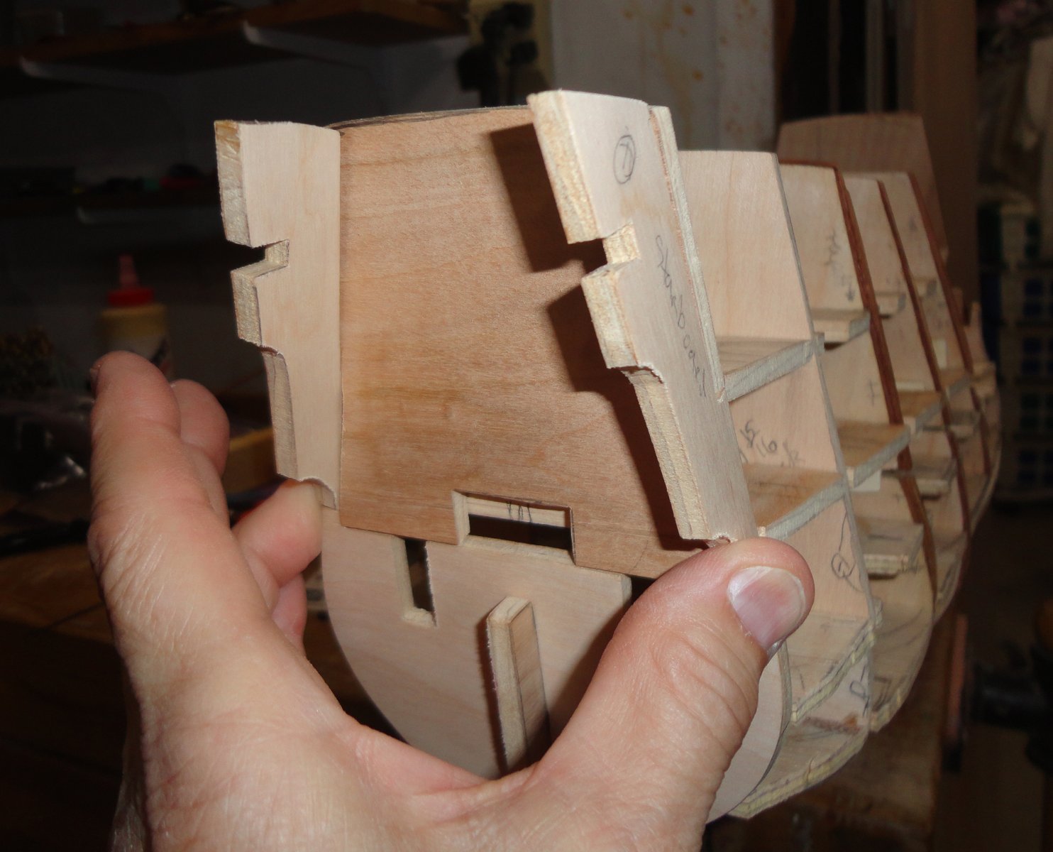
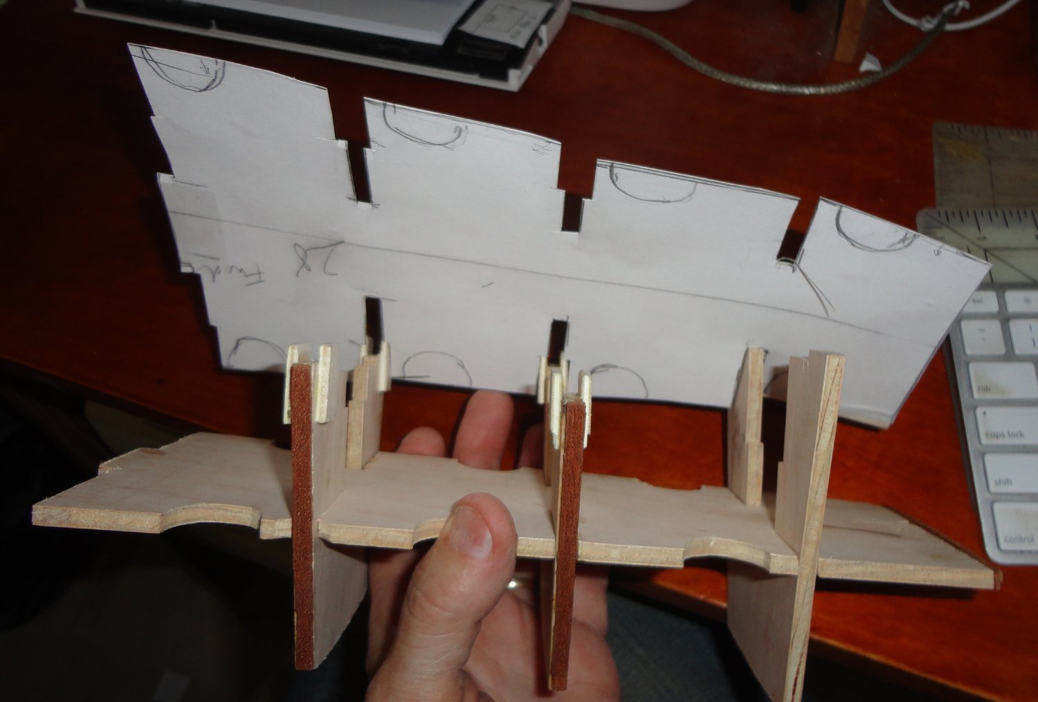
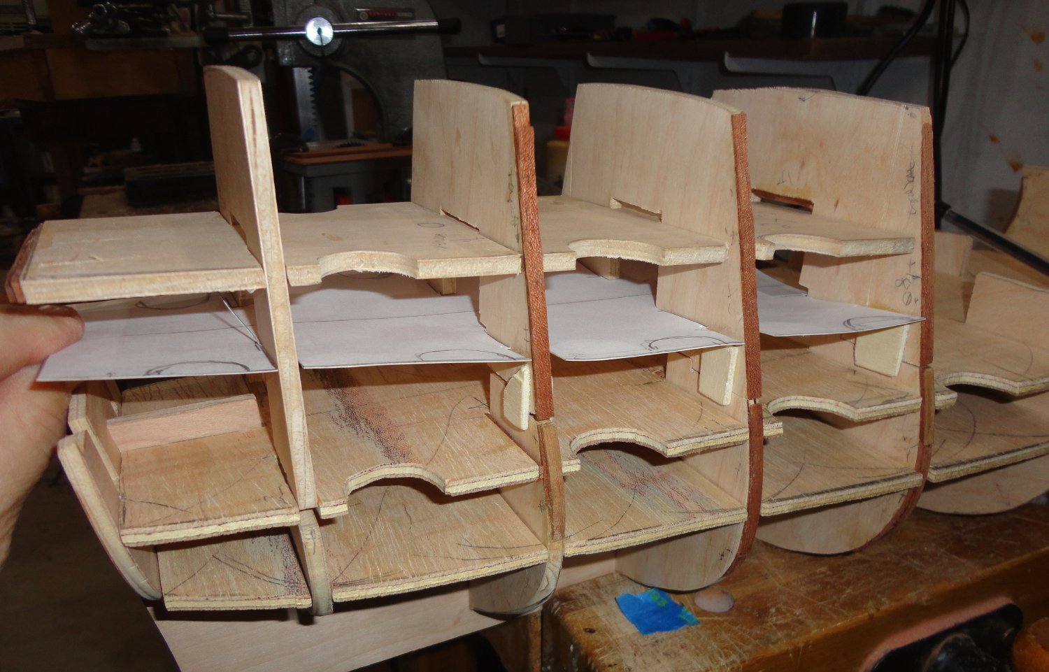
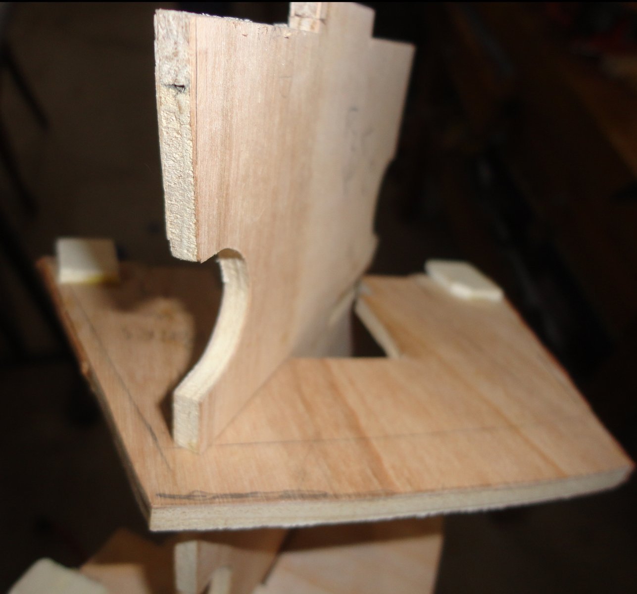
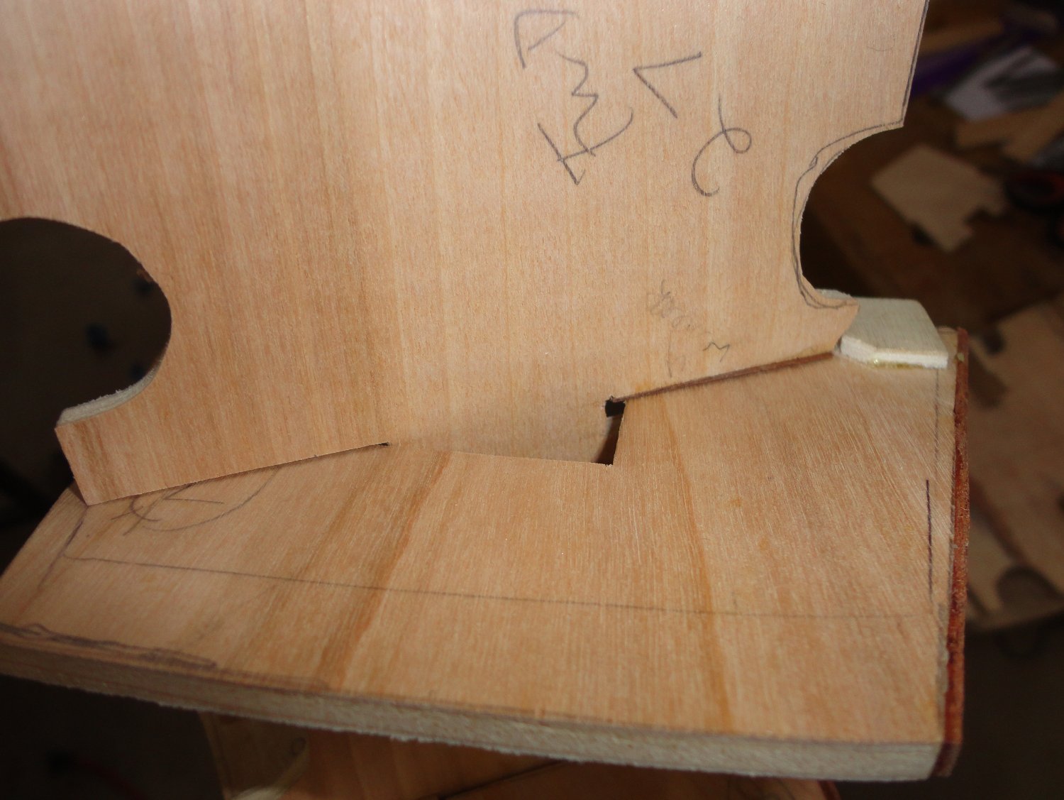
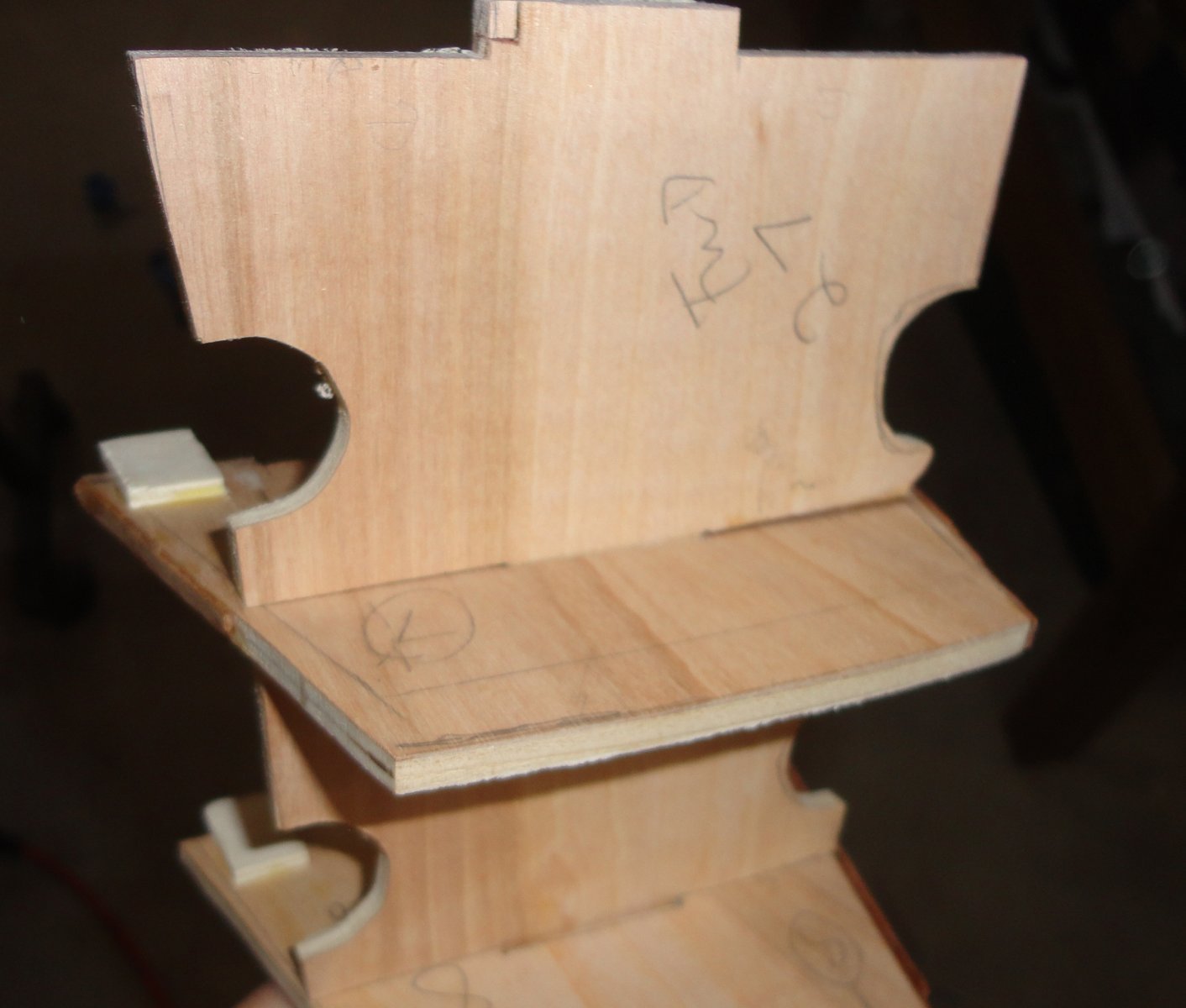
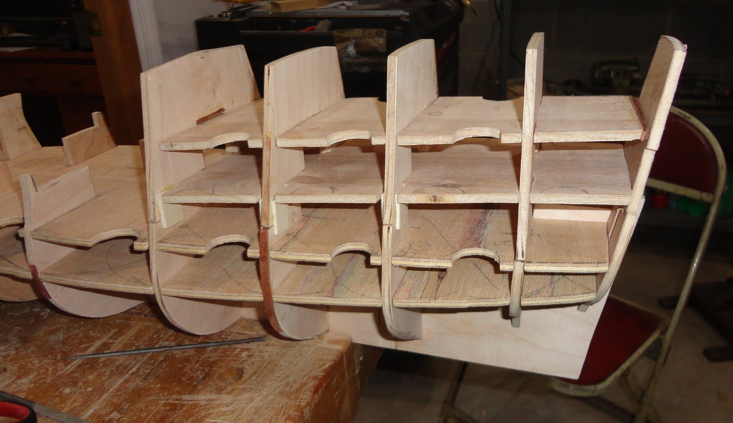
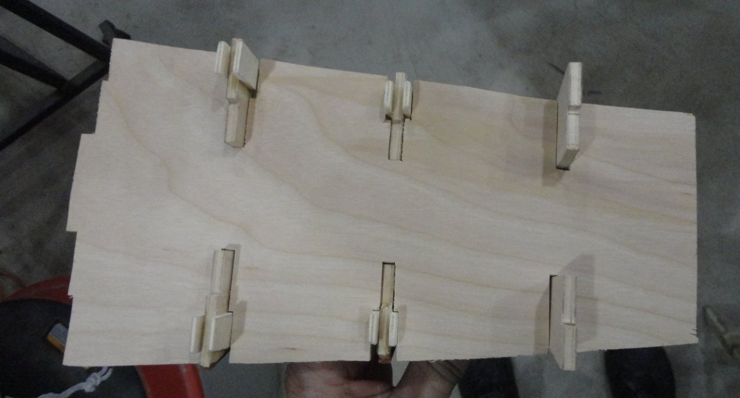
With the air cleared and a few items knocked off my 'list', more headway has been done on the GH. The first of the two enclosed decks above the weather deck in the astern castle took some care to do without wasting some wood in the process, so I drew (with frame pieces done already as partial templates) a pretty close approximation on paper. Then I used a glue stick to affix it to a piece of manilla file folder stock (card stock would have done) before cutting out and trial fitting. That way, the pattern could still be trimmed with scissors or more material tapes on as needed ... no fussing with wood yet. Below is a picture of the pattern being trial-fit to the stern castle frames. The cut-outs are staggered to make fitting gun mounts easier as the hull is planked from bottom to top later - the gun array being staggered from deck to deck. After a few goes, the pattern was a much better fit than if I had gone right to wood. Note the tabs (on both sides, other than the one on the right) of the stern castle frames (except the one on the left). This was helpful in getting everything to fit and not just fall over if bumped. I also want to make both castles removable to make planking from the garboard strake easier while the hull is overturned. Now the deck I will transfer to plywood (from the re-enforced paper pattern) has relief notches that will slide right over the tabs on the frame bottoms. I did not want to cut such notches in the deck above since it is narrower ... so how (pray tell) are the two middle frames to slide over the upper deck? The sequence is as follows: The frame is tilted as shown below, to get one corner up into the frame. Then the frame is swiveled over (note the small clearance notch on the right as shown above) to seat as shown below in two stages. No worries, mate. I only had to cut one deck piece using the revised paper pattern, with a minimum of adjustment by filing. Below it is sliding right onto the frames since there is relief for the tabs. This is all like designing a puzzle - which I find therapeutic as I always liked 3D puzzles - only in this case I'm designing my own 'kit' in the desired scale and configuration with the Sergal material only as a starting point. The last picture shows the present state of the stern castle in progress, and things are beginning to take shape ... with more fitting and adjustments to come. Steve mentioned the concept of 'bodging' ... and that made me recall the original British reality show called Junkyard Wars - where each week opposing teams had a limited amount of time to put together a technical challenge from all the material found in the show's Junkyard (shop tools and equipment were provided, of course). The moderator referred to the teams as 'bodgers' ... and the first time I saw the show they had to fashion a limbered cannon and projectiles, then the winner was chosen by the closest shot aggregate when live-fired at targets. Great fun ! 'Guess I'm a bodger.


- 45 replies
-
- 6
-
-
- Great Henry
- Henry Grace a Dieu
- (and 1 more)
-
That's nice how well the greenish-treated copper bottom came out. 'Shows one does not have to fuss with tiny plates or copper tape to have a decent effect. Besides, it mostly underneath and not what the observer admires most - namely the fitting-out, masting and rigging ... all well-done.
- 50 replies
-
- 1
-
-
- Perry
- BlueJacket Shipcrafters
- (and 1 more)
-
Ah yes, I find that there are applications where super glue is ideally suited. The medium 'gap filling' find is my 'go-to', since the thin variety wants to go EVERYWHERE ... including my fingers. Metal to wood or other dissimilar material joins (especially where there there is enough bearing surface) works with super glue, although very smooth flat metal needs a little roughening to give more 'tooth' for a better grip - as the super glue doesn't penetrate non-porous materials. The 'accelerator' (kicker) is also a boon, but I avoid spraying directly ... but into a small glass dipping sauce container. One side of the open dish is propped up on a piece of scrap wood so there is a little 'pool' of accelerant in the bottom. Then once super glue is applied and the item positioned, a small plastic dabber (the end of a detail brush will do) is dipped into the pool of accelerant then touched to the edge of the item to be fixed in position. The thin accelerator 'wicks' onto the mating surfaces and 'kicks' the curing reaction to permit quick assembly of other items. A little goes a long way, and the supply of accelerator in the dish will stay for 1 - 2 hours as it is slow to evaporate.
-
Yours is a fine build, with much to share with fellow builders !
-
The sun was out this morning, and the polymer sand in the walkway interstices seems to have firmed-up a lot in the places protected by plastic during the shower yesterday. Other places are still a bit soft where excess water seeped - but showed some progress after a couple hours of solar warming. There was enough leftover sand mix to fill cracks between the road pavement and the curbing which I power washed out yesterday, so those were gently watered. I had a lunch break and went out locally for a couple things and immediately noticed that the smoke was back (they said it was coming in during the AM news) ... and the forest fire smell is distinct, as is a fog at ground level that dims the sun by about half. I used to grow orchids under 'shade cloth' to prevent leaf scorch on Cattleyas, so I know what filtered light looks like. Its also the way things can seem during a partial solar eclipse. Being out, my mouth felt dry and I coughed a little - the particles are so fine that even a N-95 or KN-95 mask won't keep them out - only a lab grade canister face mask. So its good that I'm now inside and will try to get a little more done on the GH structure - like with house building, the framing is done first before the clapboards go on the exterior. This smoke thing brought to mind an old rhyme: It's not the cough that carries you off, but the coffin they carry you off in.
- 45 replies
-
- 1
-
-
- Great Henry
- Henry Grace a Dieu
- (and 1 more)
-
OK, it's been bone dry here for two weeks, with no rain (so they said) at least until the weekend, so I thought instead of doing anything more on the model I'd do an outside chore on my (the Admiral's) list. It did get weirdly dim and hazy today and smelled of smoke ... the Canadian wildfires, they said ... and later became 'milky' and hazy at ground level. But a cooling breeze seemed to blow it all away while was prepping my paver front walk for the application of polymeric sand. The sun came out and dried up everything blasted clear by a pressure washer. The sand went in and all the excess swept clear, and the right amount of water was sprinkled to activate the stuff. All was well for half an hour, then dark clouds approached with distant rumbling heard !?//*** %$$# !! As I was trying to get plastic over the walkway the drops from above multiplied (of course the browning lawn and thirsty border plants were happy), but panic set in as I kept grabbing border stones I could pry loose to try and hold the plastic down so the walkway treatment wouldn't be ruined. &**^%% !! I think that the impromptu covering kept half the shower off, and on-line information said that a 'light' shower during curing should not matter. In fact, the directions said to wait 15 minutes and re-apply water, then do it again after another 15 minutes to be sure that water gets down deep to activate all the polymeric sand mix. Well, I did only one application of water, so I'm praying that everything will still bond. Hmmmmm, 'should have stayed in the shipyard. So much for weather forecasting.
- 45 replies
-
- 1
-
-
- Great Henry
- Henry Grace a Dieu
- (and 1 more)