Snug Harbor Johnny
-
Posts
1,501 -
Joined
-
Last visited
Content Type
Profiles
Forums
Gallery
Events
Everything posted by Snug Harbor Johnny
-
 As the soldier hiding behing a plant said on the TV show 'Laugh-in' ... Veeeeery interesting ....
 -
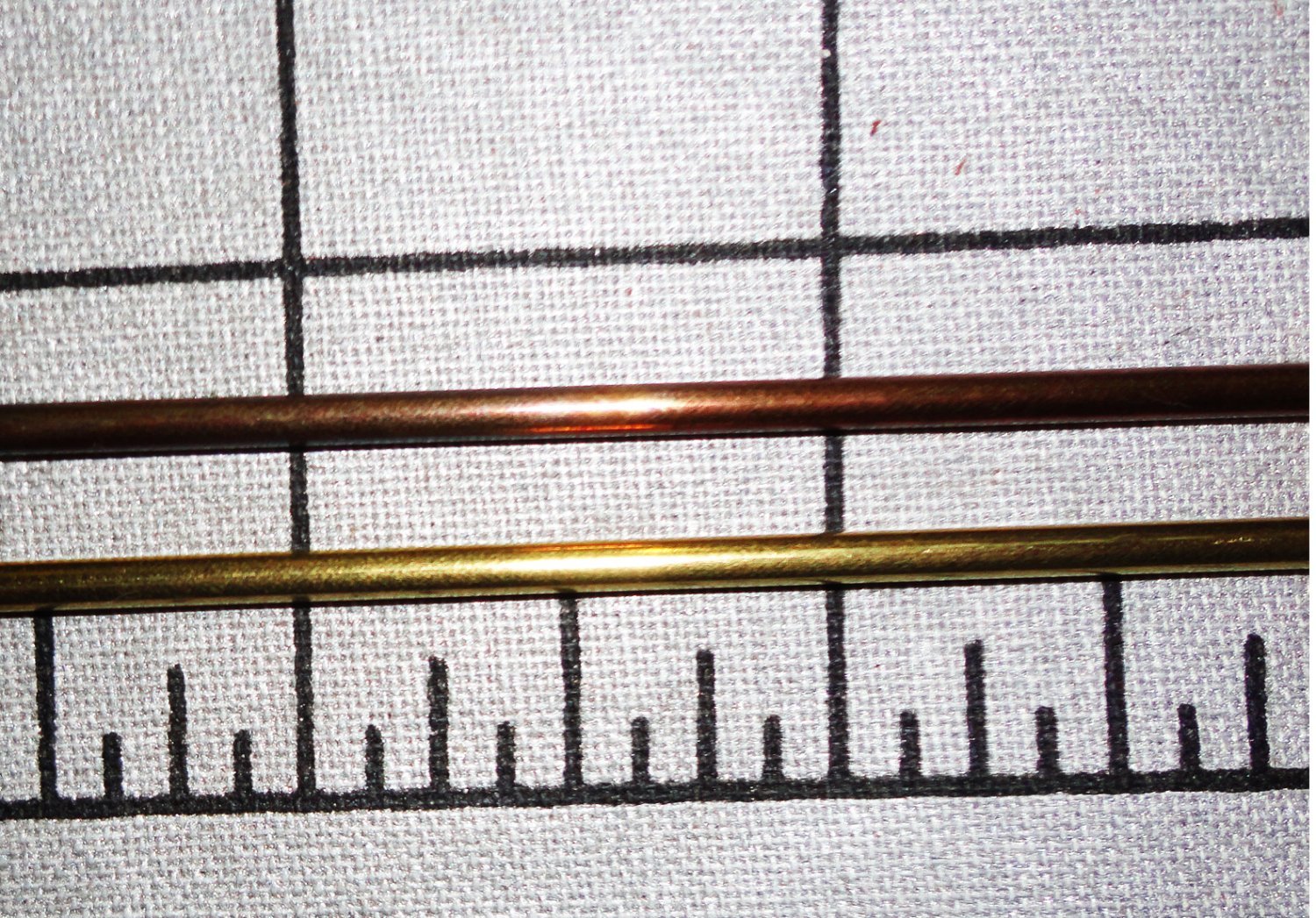
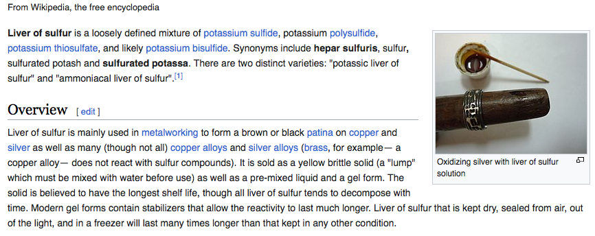
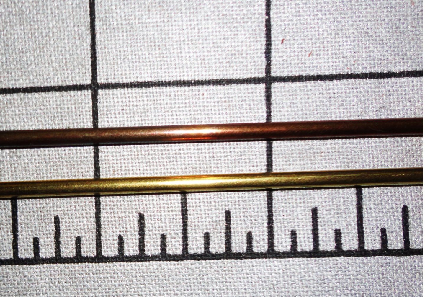
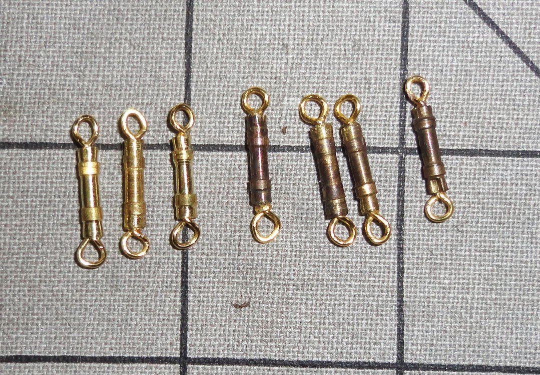
I realized that my single point cutting tool (mostly what I've used on brass and aluminum - but a few things in mild steel) was likely dulled, and an examination with a 16x loupe confirmed this. The flat faces were lapped with a little water against a finishing stone and looked at with every few strokes. This improved the point considerably. The point was also a little below 'center' with the length it was extended to, so a brass shim easily corrected this. The result was better cutting (duh). Fooling around with gel CA was redundant because A.) a light lubricant applied to the supporting drill left contaminated (dark) oil inside the workpieces, which had to be cleaned out with a miniature swab before any glue would stick B.) some Ca would still squeeze out during crimping and have to be removed once cured C.) 'Getting the hang' of crimping followed by a pull test using a pin through each eye and pulling well more than a shroud could exert proved that properly crimped eyes in the turnbuckle bodies will not fail ... due to proof testing each one. D.) any glue residue makes it more difficult to darken the brass, unless painting is chosen. The next consideration was how to darken the brass ... and there have been various discussions on how to do this elsewhere in MWS. Some methods take a relatively long exposure, and I thought I'd like to find something with 'quick results'. After fooling around (like some alchemist not knowing what to do) with a variety of things on hand, I stumbled upon something that is good enough for me. There were two agents that were tried separately, with no apparent effects - not even when looked at the next day. But applying one first with the corner of a rag moistened by the agent (wearing disposable nitrile gloves, of course) - then applying the corner of a second rag treated with the second agent ... an immediate chemical 'browning' occurred. I'd liken this to something made of shiny brass that was allowed to slowly take on a brown patina through oxidation - and that can take a long time to occur naturally. The first agent is known as 'Livers of Sulphur', and is used by jewelers, so I suppose can be found on-line. I happened to buy a small plastic bottle of it at a gunsmith shop specializing in 'old time' gunsmithing ... Pennsylvania long rifles, as hunting is a popular sport during an exclusive black powder season in PA, where there are extensive state gamelands set aside for hunters. A description is pasted below: Note they say it does not want to work on brass, which I can confirm by trying it alone. But the second agent is an 'instant' gun blue - also bought at the same gun shop, but is generally common to many gun shops as factory bluing may need re-touching due to abrasion or rust spotting due to delayed or incomplete cleaning after use on the range. Birchwood-Casey is a common brand name, but there are others similarly formulated with phosphoric acid, cupric sulfate and selenious acid ... note that extensive direct contact can result in the absorption of selenium, toxic in excess of the trace amounts found in foods and vitamin supplements (so wear gloves ... but it is swallowing the stuff that can be fatal, duh). Both agents can irritate skin due to acid content, but the nitrile gloves are more than adequate protection, and there were no fumes that I could detect. So rubbing with liver of sulphur (sparingly), then with the instant gun blue produced a quick browning of the brass. The photo below was on the brass tubing stock I'm using to turn the turnbuckle bodies, and the flash of the camera makes the visual comparison less clear, but the untreated tube is bright brass versus a nice brown patinated tube - like one lying around a few years. Below are the few assemblies I've made (not many really, and I'm working on making better eyes and cutting better bodies), all but one of which had CA applied (an unnecessary step per my above comments) before or after assembly ... the ones on the right are patinated while the three on the left are not (for comparison). The one in the center was the last one made and NOT glued ... it seems to have browned the best. The eyes are made of jewelry/beading wire, and must be coated to keep the wire bright over time. I'll have to see if there is a solvent that will take the coating off ... or I'll simply leave them as they are, since a little brass can 'pimp' the model. Actually I've no objection of using brass on a ship model, as those items will eventually get a natural toning.
-
This seems to be a 'rabbit hole' you're peering down, at least from the content of one article that turned up on a casual search: https://alkony.enerla.net/english/the-nexus/miniatures-nexus/miniature-hobby/miniature-size-miniature-scale Last year I build a 1:72 Khufu Solar Barge and had searched for that scale ... and there were not many offerings for ancient Egyptians, but I did find one box that was suitable. A temporarily suspended build of the Great Harry happens to be aprox. 1:88, and 1:87 is nominally HO train gauge. So I looked for 'medieval' sailors in that gauge - again the pickings were sparse (there were a few military figures that might work for medieval soldiers carried on board). So if you are sure of the ship model scale you are (or will be ) making (e.g. 1:48), then it may do to search for that scale and see what comes up.
-
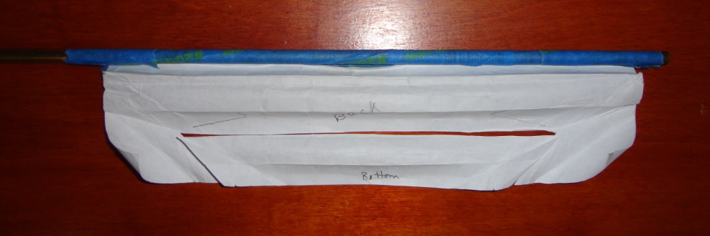
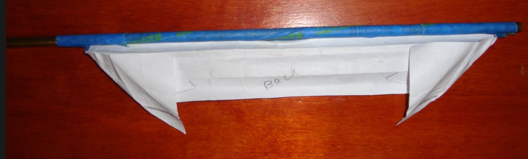
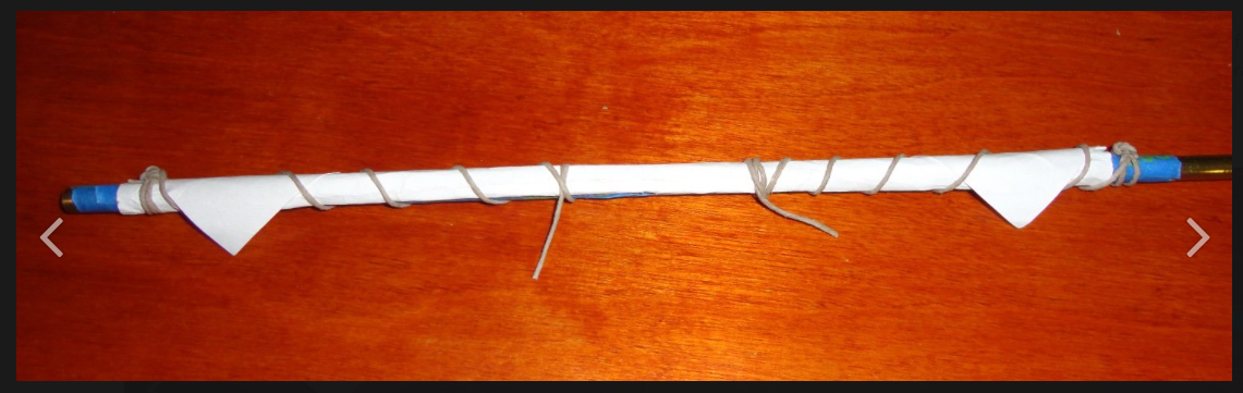
As posted way back a year and a half ago, I test-folded a mock paper sail 'clewed to quarters' as it could then be bunched up to the top of a yard - just to see if 'dog (or mouse) ears' could then hand near the ends of the yard. Now the paper did get thick with all the folding (as opposed to the remarkable thinness of canvas on an actual ship), so a section was cut out of the pre-folded paper to reduce thickness somewhat - then refolded. Sure enough, I thought the result looked OK (the ears could even be smaller and twisted a little to make them look thinner). So can this be a case where one can have the cake and eat it too? That is, one can clew to quarters and still have the ears on the furled sails hanging near the yard ends by pulling the clew outward during the folding process (ergo the clew line would have to be loosened). My test photos follow: Men standing on the foot ropes would pull sections of sail up the front in sequence. The yard below was flipped to the front side.
- 399 replies
-
- 2
-

-
- cutty sark
- revell
- (and 2 more)
-
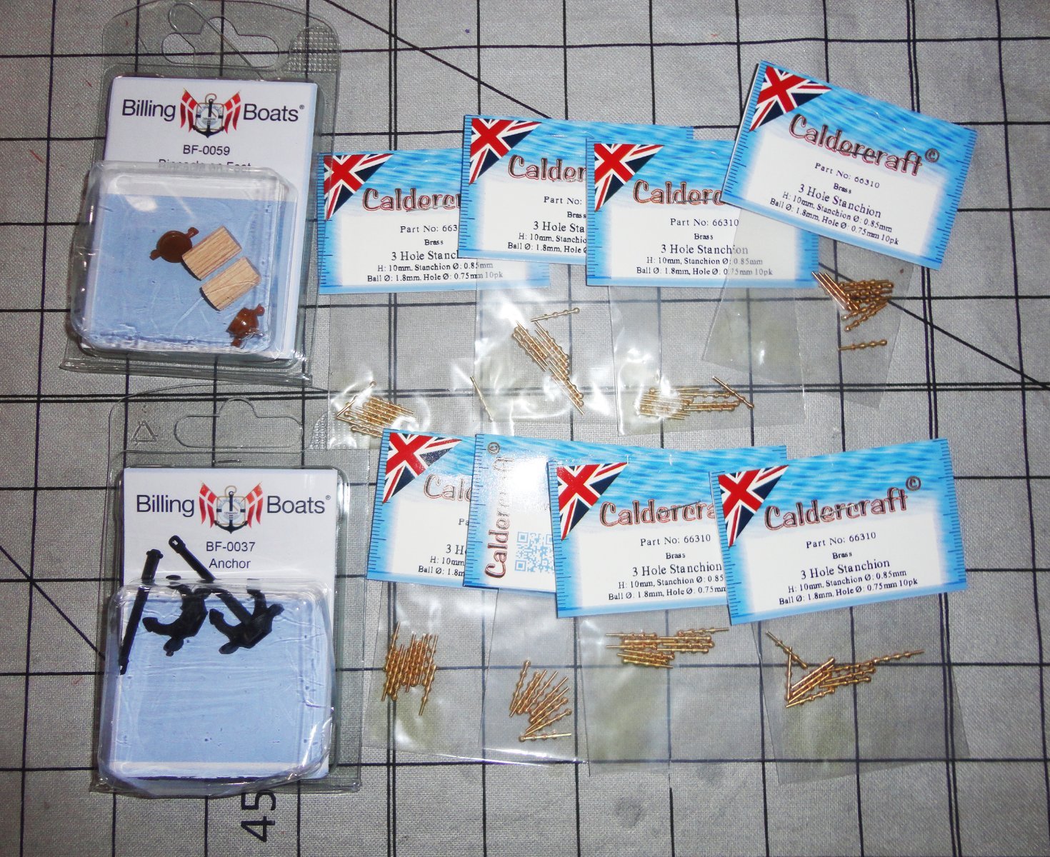
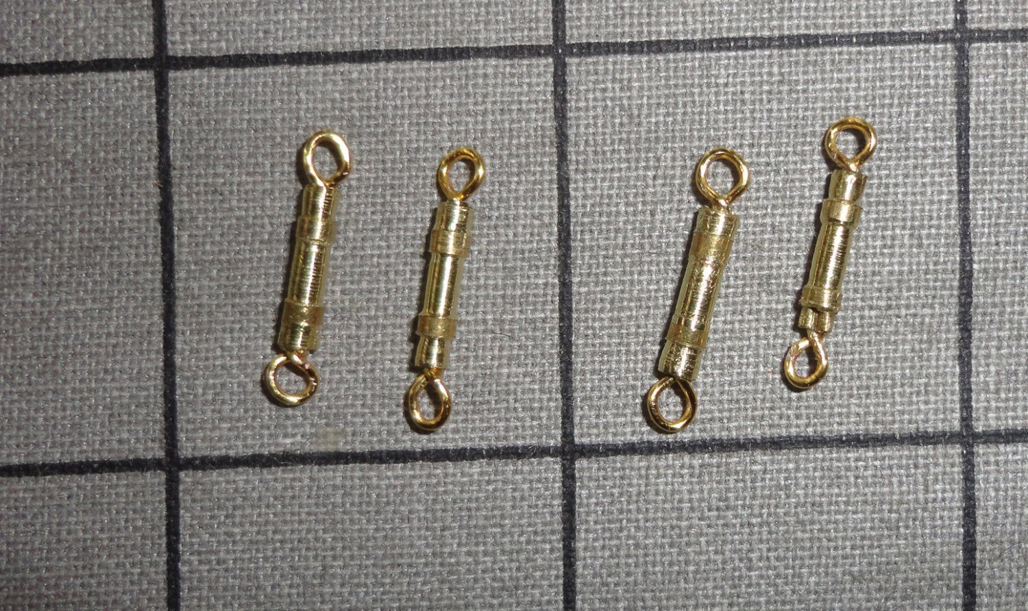
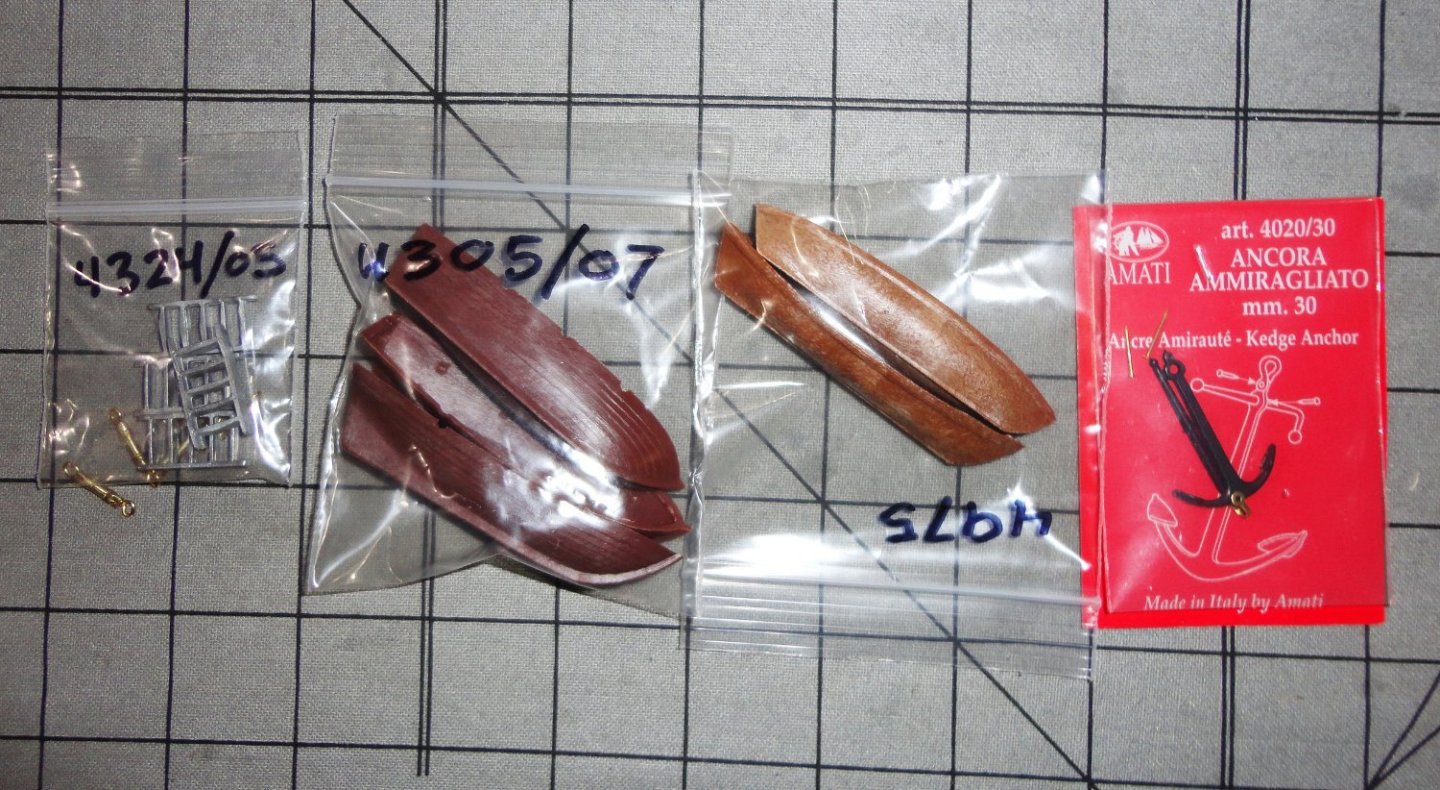
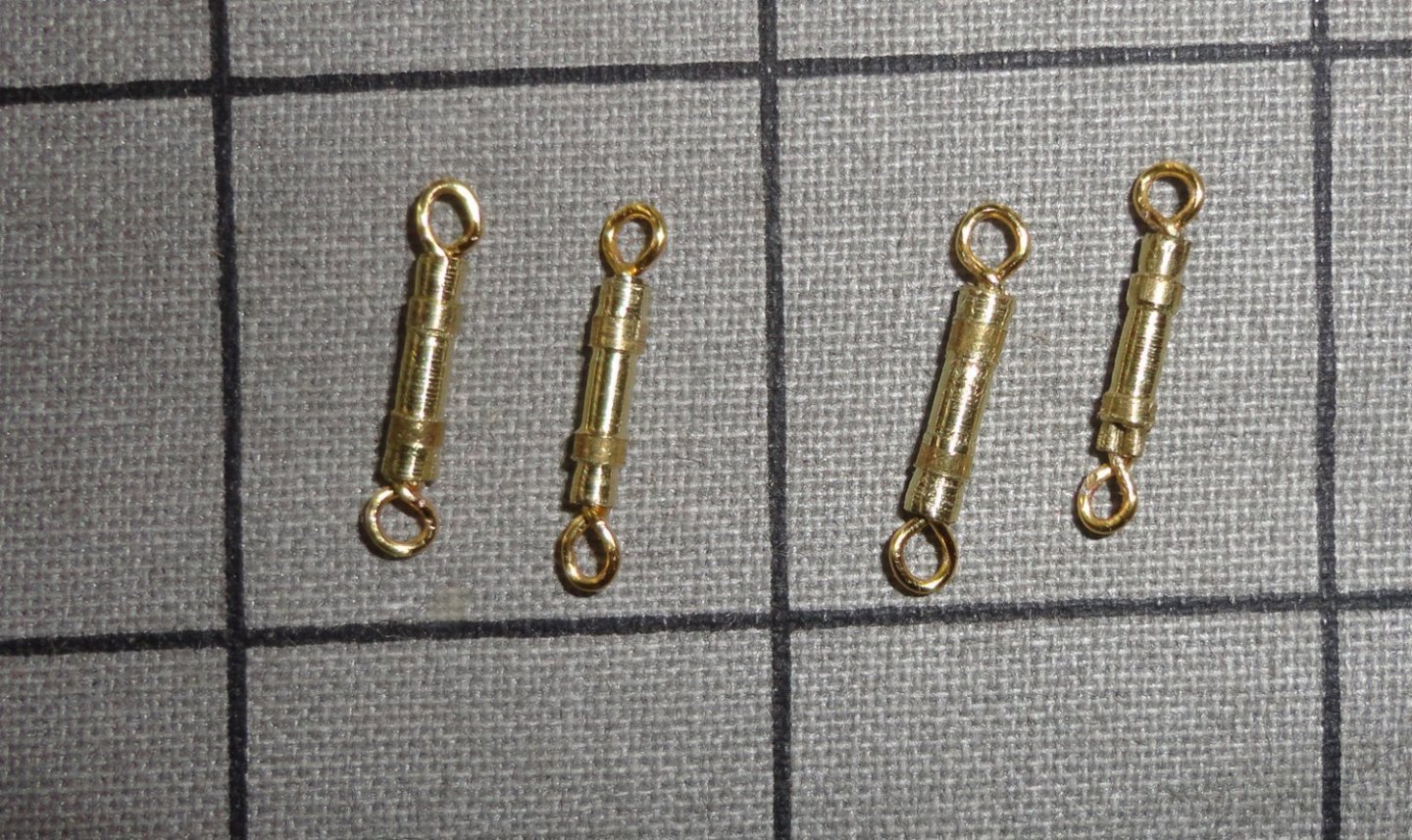
Today (my only day off from hospital service this week) my order from Ages of Sail finally arrived ... since the parts needed for the restoration (plus a couple other items) just topped $150, they shipped for free ... But the lowest price (for the shipper) FedEx ground coast-to-coast did take longer (9 days) than if I'd paid extra for expedited service. Since I wasn't in a rush, that didn't matter, but if you need something in a hurry, then by all means pay to save time. The first picture show the 80 3-hole stanchions ordered to replace the crude nails used on the model (likely what was available at the time). They are the right size for 1:100. There are a pair of binnacles and modern anchors, but I'll use only one of each. The modern anchor goes on the starboard side against the hull (fully retracted). Its alway 'like Christmas' when a shipment like this arrives. Next up are some ladders, two sizes of boats - life boats to be stored forward, and two smaller boats for the aft davits. There's and old-fashioned anchor to go in the deck area allotted for stowage on the port side. The additional items include a 2-bladed prop for the Endurance eventually to be made (I plan on using the 4-bladed metal prop from that kit on the Gorch Fock), and the single hole stanchions (also for the Endurance) that I couldn't get earlier from another source. The aprox 1:70 scale of the OcCre kit means the 15mm stanchions represent about 41" high ... close enough. There were no 12mm available that would represent 33" and 10mm would have been too short. And yes, covered by the pack of ladders are three more turnbuckles made for the Gorch Fock - they are pictured separately below. I'm beginning to get a little practice with them, and made three in 1 hour. There is some variation in size, since I'm 'eyeballing' it at this scale - but not too much and I can always sort them so that the slightly shorter turnbuckles will be aloft, and everything at each level will look alike. With more practice they will look a little better, and I should be able to do about 4 an hour. 'Did another look and I'll need at least 74 altogether ... with some rejects (and breaks) that should take 20 some hours to do. Likely this will be spced out over a number of days.

-
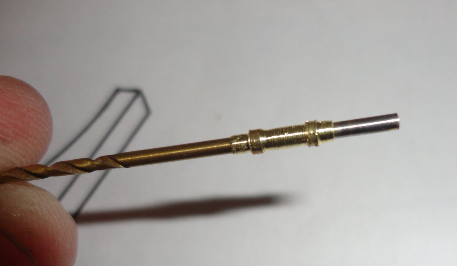
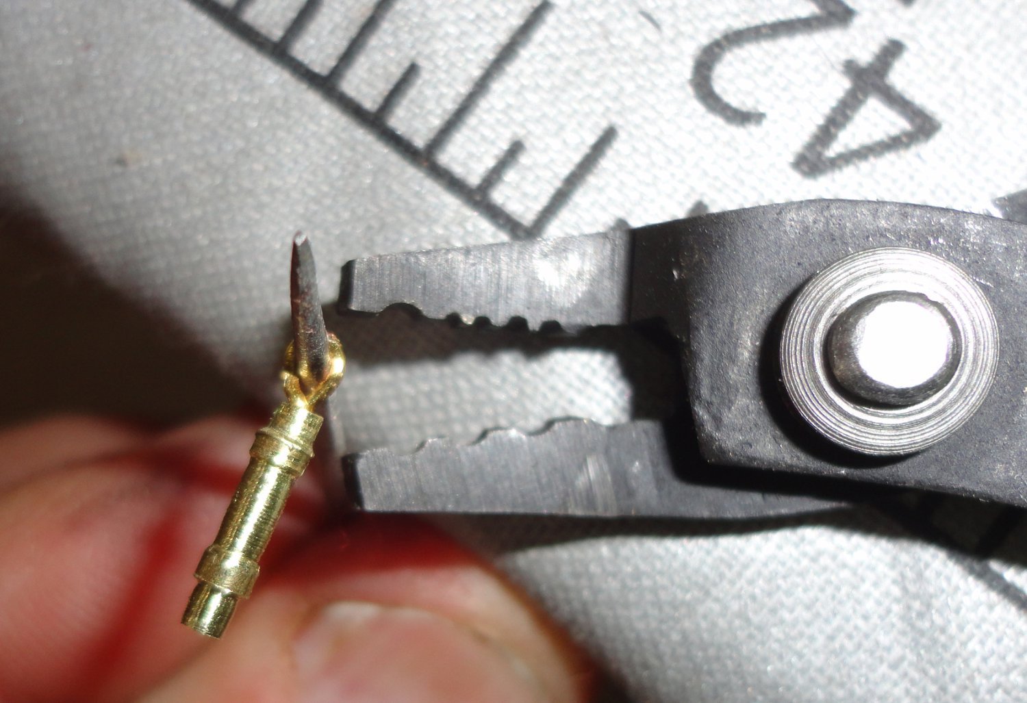
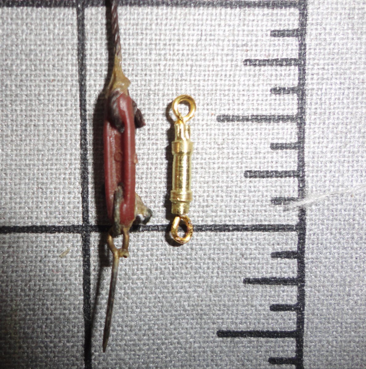
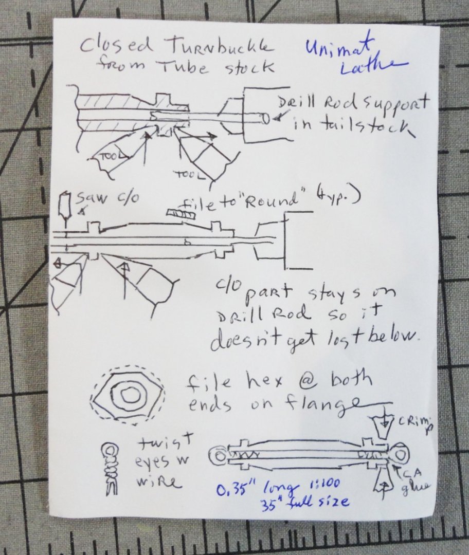
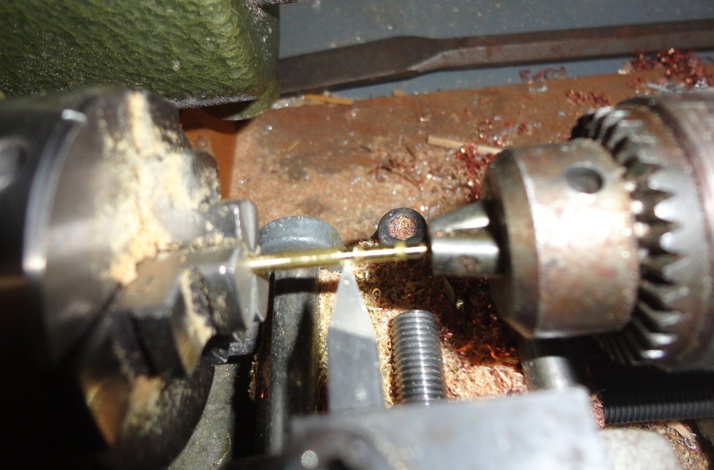
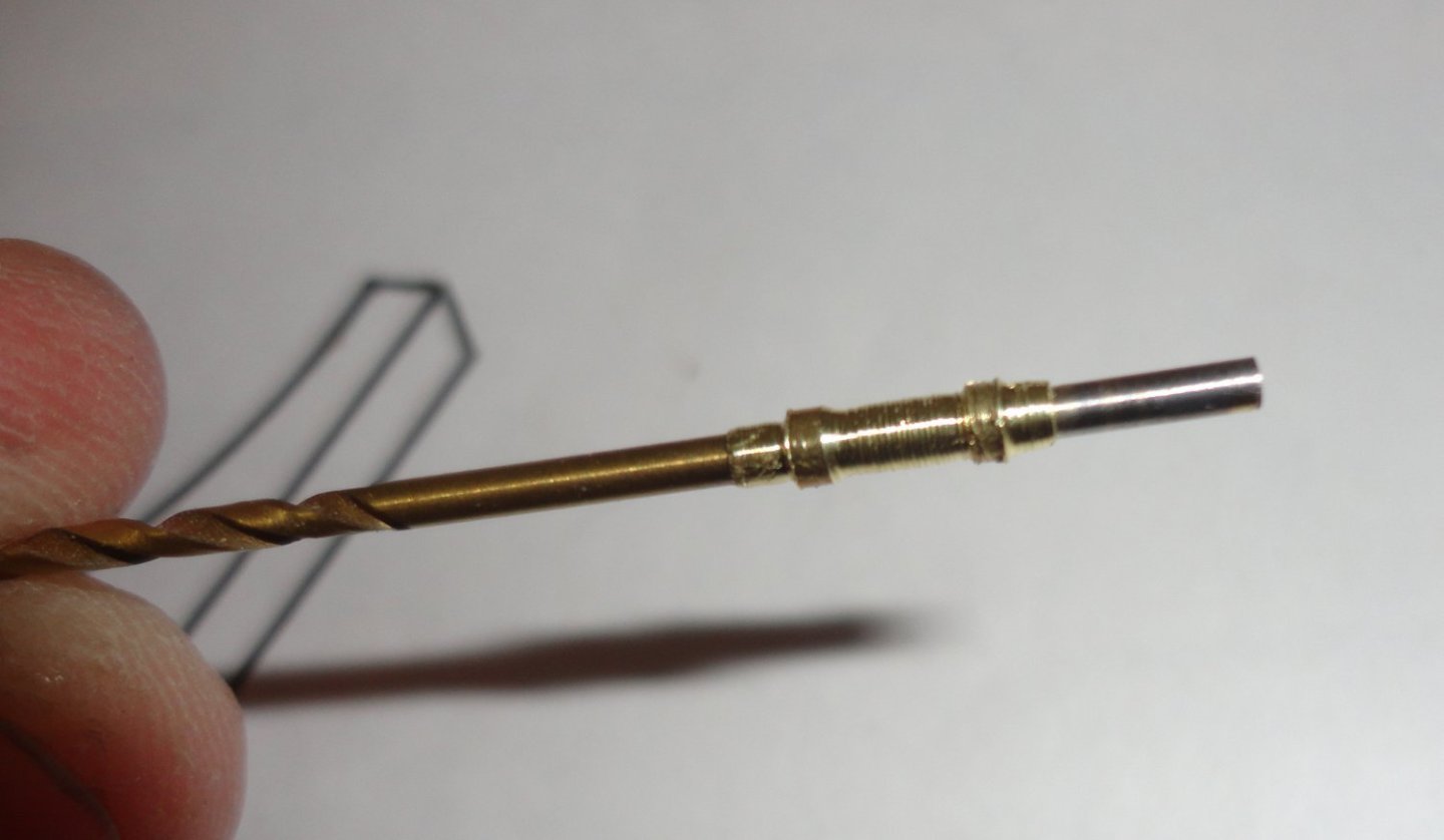
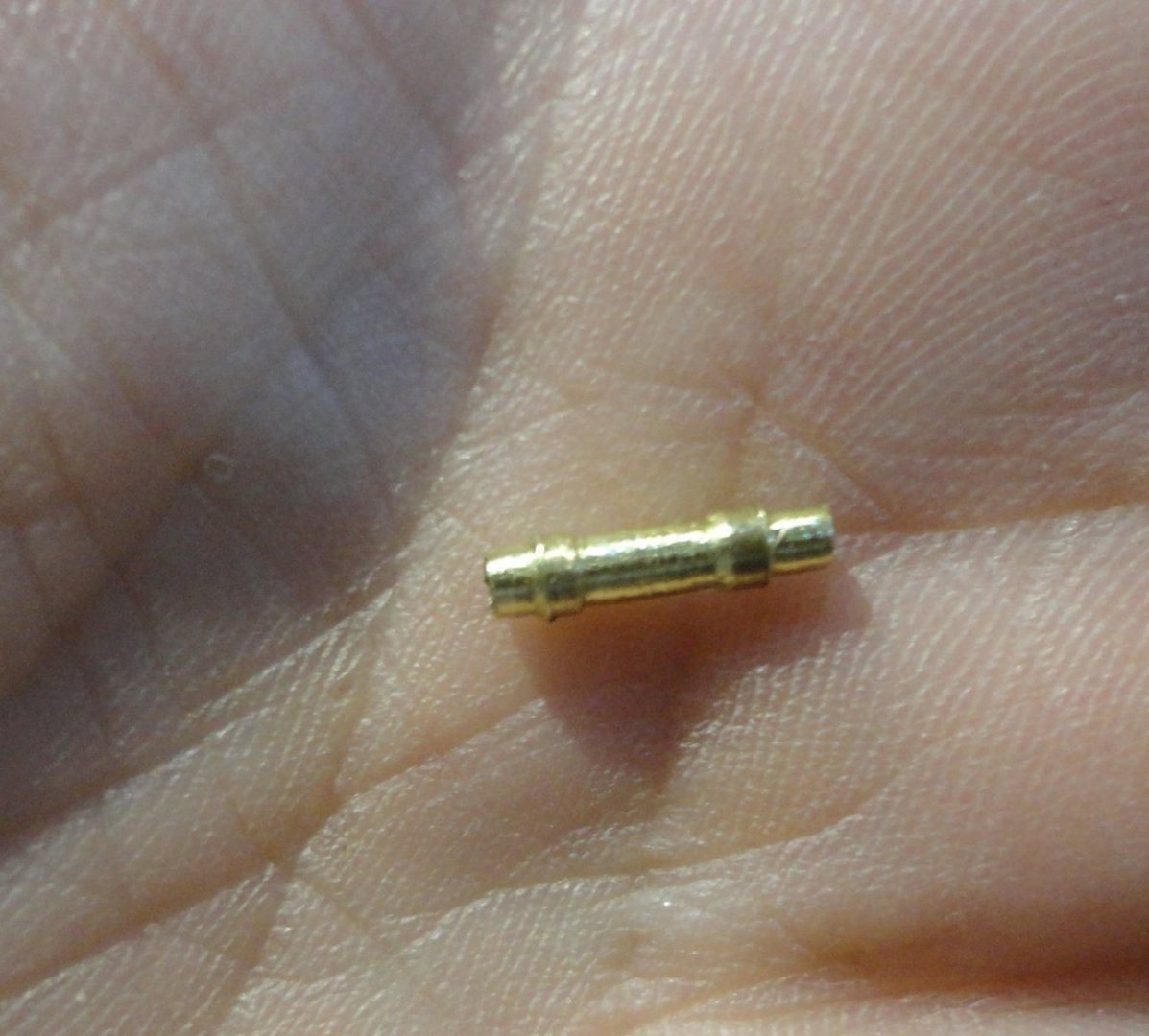
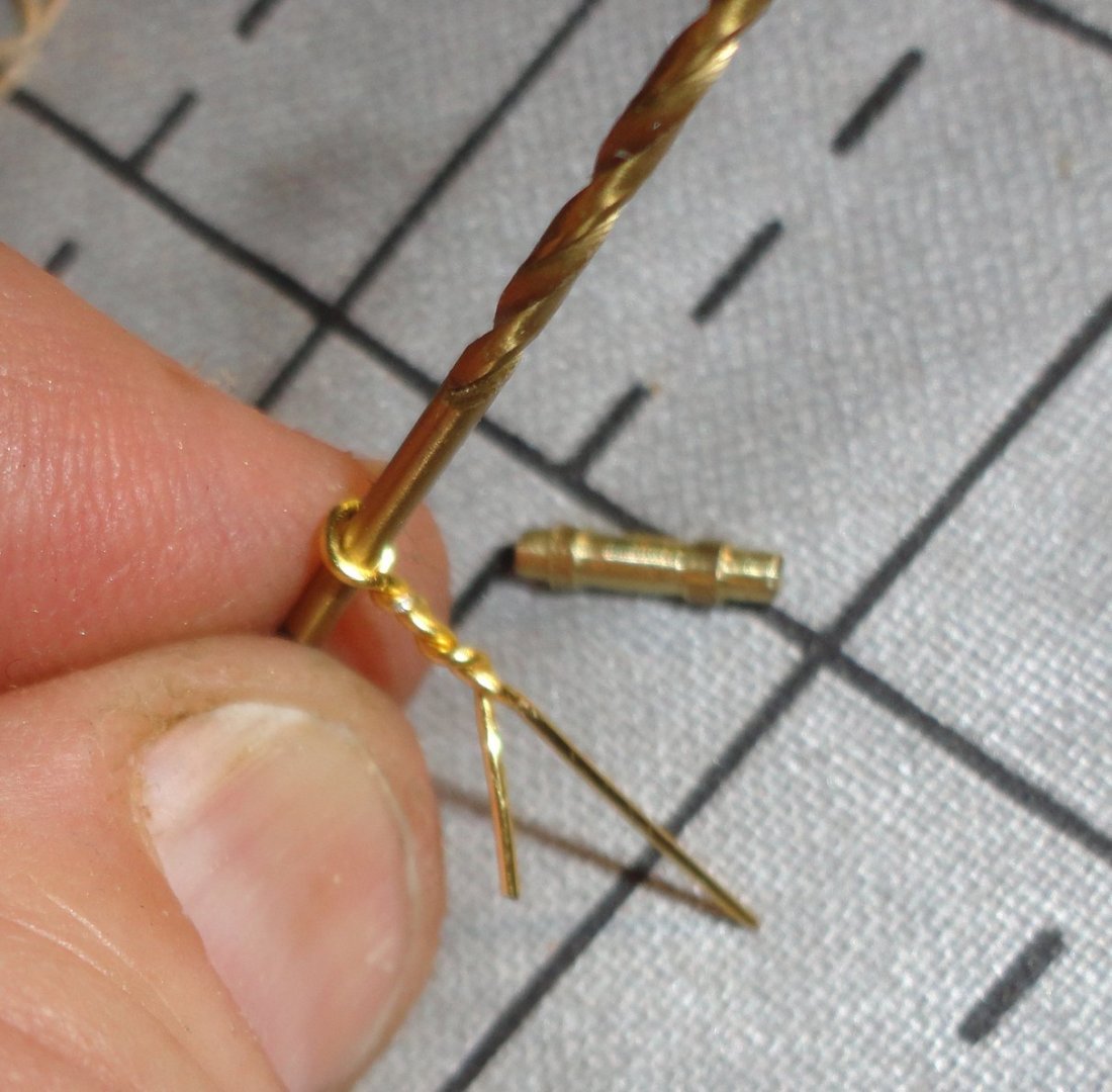
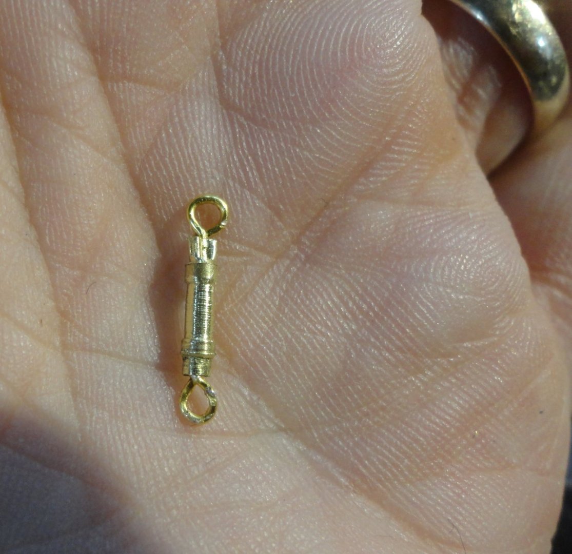
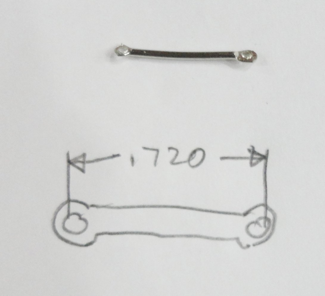
Well mates, a detail very important to this project is how to handle the closed turnbuckles for the shrouds. The crude cast deadeyes in pot metal (common back in the day) don't jive with the original ship, but were likely what was available and practical when the model was built. A number of concepts were considered, concurrent with whatever else I've been doing (except when 'focusing' when special attention was needed). At last I tried to make a 'plan' with a sketch (pictured below), that might make sense to someone familiar with machining. Yeah, my first few attempts proved that theory and practice are often different things ... and the smallest brass tube easily available does not have enough wall thickness to machine per concept. The space available was tight to avoid excessive bending of the material (which did indeed bend some, so light multiple cuts were needed). The 'hex filing' (how a turnbuckle works, by twisting the body so the opposing RH and LH threads will either pull the ends inward together or outward) is just not practical with so little material on the tiny piece available ... but at 1:100 it doesn't have to be represented. Below is a photo of the lathe spinning ... the camera managed to 'freeze' the chuck, but the higher frequency vibrations on the workpiece make for a little blur. Simple cuts were made with just the tool seen. As planned, the model trail track saw cut through the brass tube and let the part slide on the drill - sown taken out of the tail stock below. Moved off the drill bit, you can see the small size in the palm of my hand. (A little out of focus - and I've been having mechanical/continuity problems with the Admiral's cast-off camera ... I may seek something better.) The next step is to make a couple eyes by twisting 22 gauge beading wire around the same drill used to support the brass tube in the lathe. Each eye was put into one end of the closed turnbuckle body. Crimping with the semi-circular opening of the bead working crimper didn't work out, and deformed the eye a bit - fixed with a fine awl. You can see that the next two crimping spots have a 'teat' on one side that proved to be far better to secure the other eye (also used on the first eye) without distortion. Below is the first successful turnbuckle made .. a little 'rough', but I forgot to apply a fine jeweler's file while still spinning on the lathe to even out the fine waves that are inevitable when machining (they also show more on a small part magnified by photography. In the corner of the picture, part of the one ring of power can be seen - at least it exerts power over me (We serves the Mistress of the precious). Now there are over 50 of these to make (plus some extras), so that will occupy me for a while ... goes with the hobby. The last picture in this post compares a fitting from the model with the type I plan on using in the restoration ... both about 1/2" OAL - a little out of scale, but I can't easily make turnbuckles any smaller (not that it is impossible, but I'll go ahead with what I have at hand). 'Feels good to have moved the ball a little further downfield.


-
'Like the look of individual gaskets tied with a reef knot done with a bight of rope - so it will hold just fine but can be loosed by tugging on the free end of the loop.
- 399 replies
-
- 1
-
-
- cutty sark
- revell
- (and 2 more)
-
We're all free to build any configuration so desired. I like the look of the detailed steering gear that some have modeled, and don't forget, once ice-bound the shed over the gear was removed and put on the ice flow for storage. So a build with late modification without the shed is just fine. And the deep-sea photos of the ship as she rests do not show the shed. The book 'Endurance' (available in paperback) is a thrilling read and adds greatly to one's knowledge and appreciation of the expedition. There is also a 'boat in a bottle' build showing the Polar configuration with the extended Ritz with decking above. The "T" shaped roofing/dog run is gone (as seen in polar photos), and so are many of the stanchions/railings in that area. I'm with you on the Polar version simply because simplifies some of the build ... and I'm one for taking the path of least resistance. The 'rolling yard' seen on a recent build is intriguing ... and then that eliminates bunt and clew lines for that sail - another simplification. Looking forward to your build ! Johnny
-
You've chosen a great kit to build, and appear to have some good plans in mind. As for the 'configuration' of the vessel, that kept changing as they preparations for the expedition progressed. Thats why a set of random pictures of Shackleton's Endurance can be confusing. There is the way it looked after initial modifications in England - which appears to be about how the kit is set up (except that the steering gear was still exposed at that time - the wooden 'shed' to protect the steering gear from ice accumulation near the pole was added when more changes were made in South America). In South America more modifications/changes were made, including enlarging the Ritz (thus increasing the run-out of deck amid ships) ... one has to sort the available photos as to location and time to see what they did and when. Once on polar ice more changes were done, but they were stuck for good at that point. So there are easily three 'versions' than can be modeled, as changes were made in stages. Fair Sailing ! Johnny
-
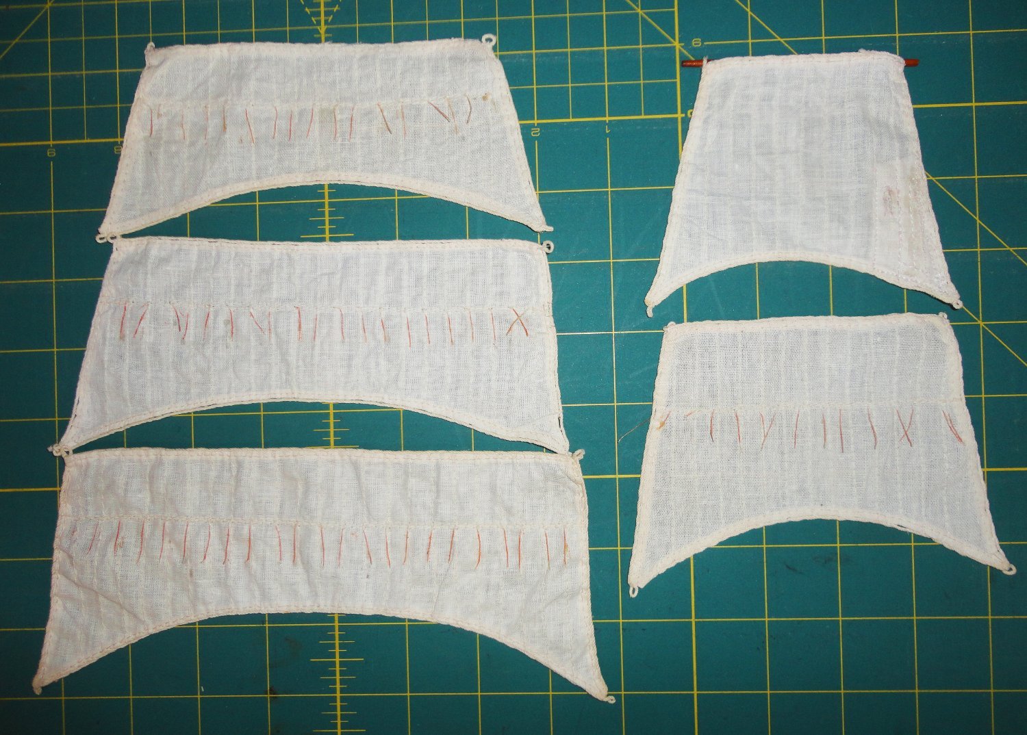
'Tried using a 50-50 clear/amber shellac mix to test on some reef points per the previously posted 'straightening' method - since the pale threads seemed nearly invisible against the cleaned sail material. This was to see if I could eliminate a step, the first step being to tint the points with water color prior to using clear amber to tame the 'flyaway' nature of loose threads. I wasn't keen on the shortcut for a few reasons - so the tint first, then straighten with clear shellac method was settled on with a reasonably good result. The reef points are not really 'glued' to the sail (but the micro fibers do tend to adhere), and portions of each point (and some in their entirety) are free of the sail. Yet they remain relatively straight, but with slight bend in some - which seems 'natural' in that they are NOT strictly in rows like men at attention. It is better than a 'bad hair day' appearance for sure, which they had before. The topmost sail has no points. Looking closely, the method of reef point application appears to be passing a fine thread from the back (leaving a tail loose), passing the needle back through the sail a couple warp threads over and then back out the front through or near the original needle hole. No knot was needed, Now I'll have to dismount all remaining sails (keeping them in order with the yards from their respective masts), clean then treat the points. I've ordered appropriate three-hole stanchions for better railings from Age of Sail, as well as lifeboats, a prop and two types of anchors - plus a few odds and ends. I saw an interesting picture recently, so I'm attaching it to this below:


-
Thanks for catching my typo ... the spell Czech does not catch a goof spelled correctly (or suggests something odd for a typo it DOES find). Were the scale really 1:72 the model would be over 4 feet ! The actual kit scale of 1:162 is just a tad smaller than the one you are building - and nicely done at that. The edit to my original post is pasted below: Edit of 8-3-23 OOPS !! My typo on the kit scales. I confused the scale of two "other" paired kits (1:172, and typed that as 1:72 - amazing what missing a digit can do). The hulls on the Scientific and Lindbergh kits measure 21". When compared to a 285' long original Robert E. Lee, it works out to about 1:162. The Lindbergh box states 1:163 (close enough) while the Scientific box states 1/8" = 1.45' ... My guess is that the 'resultant' model size of about 24.5" represents the hull PLUS extended ramps sticking out in front (OAL). The plastic hull shell and the wooden hull blank from the respective kits match each other almost perfectly, as do all the detailed parts.
- 58 replies
-
- 2
-
-
- Robert E Lee
- Amati
- (and 4 more)
-
Your though about 'steps' mirrors Thomas Edison's comments that beginning a project is like facing a very long staircase and one can't really see the top of it. But you start, one step at a time, and after a while you're somewhere in the middle of that long staircase where the top and the bottom both look far away. But you keep on climbing, focusing on the next step, and the after a while you can see the top getting nearer and nearer until you finally reach the last step. And then its just one small step that gets you to the top, and that last step doesn't seem so hard, as did every individual step on the way up. Yet, at last, you've made it and don't have to look back down the stairway finally ascended. Congratulations on your super-nice model ! Johnny
- 166 replies
-
- 6
-
-
- Maine
- BlueJacket Shipcrafters
- (and 1 more)
-
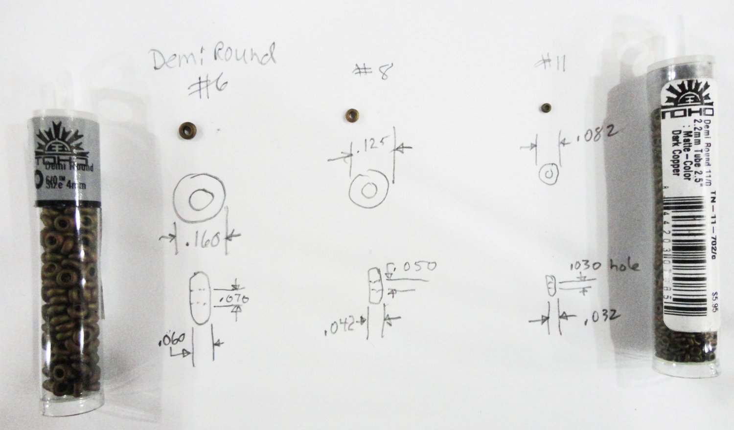
'Very busy this time of year - especially with some breaks in the heat for outside work. Yet there is opportunity to think about the project at hand while doing all sorts of other things. Guess the idea is to 'measure twice, cut once'. Considerations include: 1.) Re-thinking walnut blocks. I've always liked walnut, and for deadeyes they seem pretty good as-is. But they appear too dark for blocks to my eye, and lighter colored wood may be preferable. Now late-period clippers had internally stropped blocks for the most part, so wrapping wood blocks with line makes me scratch my head. Rob made good used of molded Cutty (1:96 kit) blocks on models he's made - yet even so they appear somewhat out of scale, strictly speaking. 2.) The scale issue. As mentioned elsewhere, a 6" block would be about 1.5mm at 1:100, and 8" block would be about 2mm and a 10" deadeye would be about 2.5mm ... all pretty small stuff for fingers that just don't want to work things that small (like mine). Obviously, going larger can help - but that can only go so far until the blocks really DO look overly large. So an idea covering two of the above came to me as I escorted the Admiral at a bead and polished stone show recently ... that is Czech demi-round glass beads in a flat, coppery-brown color - which I found at the show. In the photo below are the three sizes I bought to try: #11, roughly corresponding to a 2mm (8") block t 1:100 - meant to serve for my representations of 6" single blocks (bunt or others); #8, about 3mm or about a 12" block at the above scale - meant to serve as a nominal 8" - 10" block (single or double); and #6, about 16" at scale, meant to serve as a nominal 12" triple block where applicable. These seem to be the available sizes (no #7s or 10s), and the color could be a little lighter - but one must use the tools one has. For a simple block with no becket, I'll put a line through the bead and tie a 'hangman's noose (which nicely pulls one end of the line into the 'shank' of the noose) - then pull the noose tight on the bead block. Where a line would go from a becket, another noose is made opposite the first - simple. In some cases thin copper or black finished copper wire might be just twisted after passing through a bead (with one end trimmed close to the twist) - also simple, so it satisfies the KISS rule (Keep It Simple, Stupid). I see now the advantages of working in 1:70 scale - and even better at 1:48. Then it is much easier to use 'real wood blocks'. Now there are some highly skilled practitioners who can do amazing feats of miniaturization - and I doff my hat to them (and am tempted to build a small shrine to do homage). I'll always be glad to see truly fine work (and there is plenty of examples found on MSW), but as for me - I'm mainly trying to learn and appreciate bygone era while making something now and then at a skill level I can manage. The Gorch Fock has turnbuckles instead of laced deadeyes, yet the little fittings used on the model at hand represent (sort of) deadeyes. I found something called a 'bar' for beadwork, but it may be too large (6 scale feet) as shown below. I'm considering tying beads through a short length of thin brass tube to represent aprox. 3' turnbuckles. 3.) I'd like most of what I do on the GF to be 'reversible', for someday additional maintenance or repair might be needed. This might be compared to making work done on 'Old Masters' reversible by future conservators. Hence means of pinning, tying and wrapping should be preferred over outright gluing. As already mentioned, I'm fortunate that the masts will come right out of the solid hull, simplifying life considerably. 4.) There are no 'instructions' per-se that go along with this project - hence I'm constantly thinking things out in two ways. he first is how to accomplish what I'm planning to do step-by-step clearly in mind before doing anything. The 'other' way of thinking has me imagining I'm a 'scaled down' man who has to climb aloft to do all the functions a sailor might have to do. Can I get everywhere I need to go? Are the handholds and foot ropes appropriate. How will the lines run, and can they be managed at deck level for the intended task? The quality of instructions, detail and order of operations that go with model kits is critical for those learning the art of ship modeling. What is provided by various kits (both old and new) is highly variable in quality and accuracy. That is why the various builds found in MSW are an invaluable aid to those not expert in the craft (like old Johnny). There will be both simplifications and enhancements on this restoration, to be sure, but I think the result will be rewarding.

-
I believe the interior rowing scenes form the Charlton Heston version of Ben Hur had unseen machinery to synchronize all the oars so that the sctors portraying miserable galley crew 'rowed' with amazing unison. RAMMING SPEED !!!
- 536 replies
-
- 5
-
-
- Quadrireme
- radio
- (and 1 more)
-
Ahoy David ! I did kit review (its in my stash) that included a few enhancements ('busts'?) to OcCre's Endurance - a decent kit, reasonably priced that has a build log pretty much 'out of the box', and a couple others who have included improvements. I did order some very mice 3D brass stanchions from Cornwall Models in England, but they are not alway 'in stock': Two-hole stanchions 12mm high, 1.2mm in diameter with a base flare and two 2.1mm balls having 0.75mm holes for wire railing. The manufacturer is Caldercraft Part # 66B0518 and there are 10 pieces in a packet. They might be available form other dealers or perhaps Caldercraft directly - you'd have to do some searching on line. I bought 8 packs of the 2- hole stanchions, although they were out of the one-hole variety - also needed. Edit of 7-28-23 ... Just ordered some fittings for a restoration project from Age of Sail (in California), and they have a variety of one, two and 3 hole stanchions available (nut none of the 10mm single ball) from several manufacturers. The 15mm single hole might do (for the few that are needed) and some could also be trimmed off the bottom if not used as-supplied. Johnny
-
'Looks very nice, and the 3-D railings are impressive (as well as the PE work). You've made some good 'calls'.
- 89 replies
-
- 2
-

-
-
- Cutty Sark
- Revell
- (and 2 more)
-
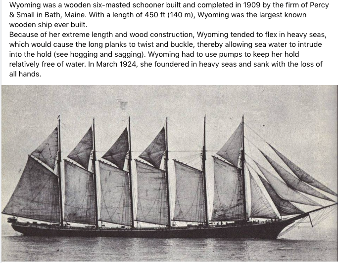
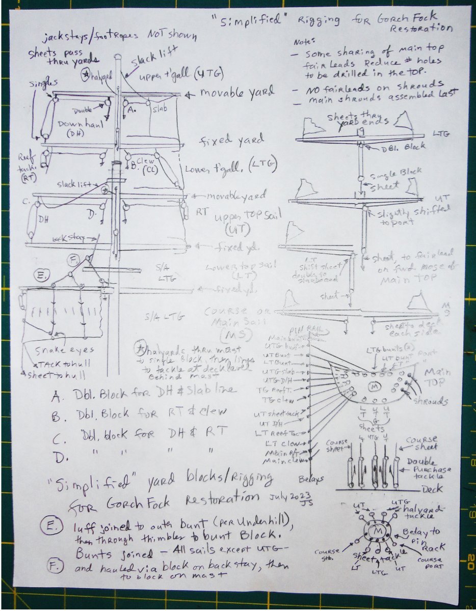
A man, a plan, a canal - Panama ... My favorite palindrome, but one that emphasizes that I need to plan out how the control lines should be routed to belaying pins at deck level - as opposed to just 'winging it'. Each line needs to have a purpose, even if simplified for this restoration, yet be a manageable compromise for the scale and scope being dealt with. The initial crude sketch was redone a bit better, with the addition of compromise fairleads to be added to the main top - to avoid having too many at 1:100. The low-end borrowed camera overexposed the central area of the sketch, but rudimentary Photoshop adjustment helped a little. The fore and main masts will be the same as far as the square sails go. 7 of the main top fair leads have a single line passing through, and 9 are shared by 2 lines. The yards will first have blocks and sails mounted, then the intact masts from the model will be fitted with blocks, shrouds and the yards off-model. Any work on the hull must precede the addition of the masts. Fore stays will be typical and fitted with stay sails as applicable, followed by rigging/belaying the halyard and sheet tackle around the masts. The lines from the fairleads get belayed before the lower shrouds are fixed and adjusted. Braces will have to be added sometime, as rigging lines become more crowded - as will ratlines. There's a lot yet 'to be determined', but a course is charted - more or less. Then there was 'Napoleon's lament' (also a palindrome): "Able was I ere I saw Elba." As for me, "Are we not drawn onward, we few, drawn onward to new era?" Johnny

-
There are six common 'seats of comfort' at the bow of Victory for some 800 crewmen .. a few less subtracting officers. Looks like all facets of life aboard were 'figured out' for efficiency - the space for crew hammocks seems barely enough (tight pack?). And even in the Admiral's area there were guns stowed that could be brought into action once the partitions were lifted out of the way.
-
'I see', said the blind man, as he picked up his hammer and saw. I'd like to complete the restoration by Christmas ... early next year at the latest, and given that my MO is often to jump from one project to another (I'm a grazer) I'll likely do more on the other two ships in the yard before then. As many have said, "Its not a race" ... and its the 'journey' that counts.
-
I think there used to be cocaine drops for teething woes.
-
I'm definitely watching your magnificent build before going much further on the Great Harry, and I'm intent on jumping into a rigging restoration on an old Gorch Fock model in the mean time.
-
'Saw a fascinating video & thought I'd share ... as long as the link stays active in the either ...
-
'Sorry mates for my SNAFU over the book title previously posted. That portion was edited as a precaution. What happened as there are two similar titles that confused me when trying to order 'The Boy's Manual of Seamanship and Gunnery' (1861, reprinted 1871), but what popped up on line was 'Manual of Seamanship for Boys and Seamen of the Royal Navy' (1904) ... two very different books, although of interest to some in MSW. I can only chalk it up to the hazards of trusting Artificial Intelligence. The latter book (once paged through) did not have the illustrations previously posted on reefing details ... or the other details sought, although it did have lots of other cool things relating to service aboard Naval ships in the 'pre-dreadnought' era. Once my misstep was discovered, better research was done on the desired book having the sort of illustrations fro square riggers ... and a 'print on demand' can be had from India through Abe Books. My edit is pasted below as further precaution: Edited NOTE: I've mistaken the title quoted below (readily available) with the ACTUAL title - The Boy's Manual of Seamanship and Gunnery , originally published in 1861 (author C. Burney, publisher Trubner & Co.). This is apparently a rare , collectible book and not readily available. Abe books offers a "print on demand" from India of the 1871 edition of the book (with shipping comes to about $30). So I've ordered one by first logging into my Abe Books account and paid by credit card to have them manage the transaction. This, method avoids having to deal with an unfamiliar seller overseas. The reprint of the 1904 book was received, and primarily deals with the Royal Navy life circa 1904. There are some illustrations of rope work and tackle as was still in use at the time, but not focused on sailing ships. Once the copy of the 19th century book is received, it will be a different kettle of fish - with more pertinent information on square-rigged ships. Still, there are portions of interest in the early 20th century book top peruse at leisure. I can comment on the copy of the older book once received.
-
'Love this steamer - and its a future project - since I discovered that the Scientific wood model and the Pyro/Lindbergh plastic version are the same scale - about 1:162. Thus neat detailed parts from the Pyro model can be used to enhance (and make easier) doing the wooden version by Scientific. I think there are build logs of both versions, as well as in larger scale. Edit of 8-3-23 OOPS !! My typo on the kit scales. I confused the scale of two "other" paired kits (1:172, and typed that as 1:72 - amazing what missing a digit can do). The hulls on the Scientific and Lindbergh kits measure 21". When compared to a 285' long original Robert E. Lee, it works out to about 1:162. The Lindbergh box states 1:163 (close enough) while the Scientific box states 1/8" = 1.45' ... My guess is that the 'resultant' model size of about 24.5" represents the hull PLUS extended ramps sticking out in front (OAL). The plastic hull shell and the wooden hull blank from the respective kits match each other almost perfectly, as do all the detailed parts.
- 58 replies
-
- 2
-
-
- Robert E Lee
- Amati
- (and 4 more)
-
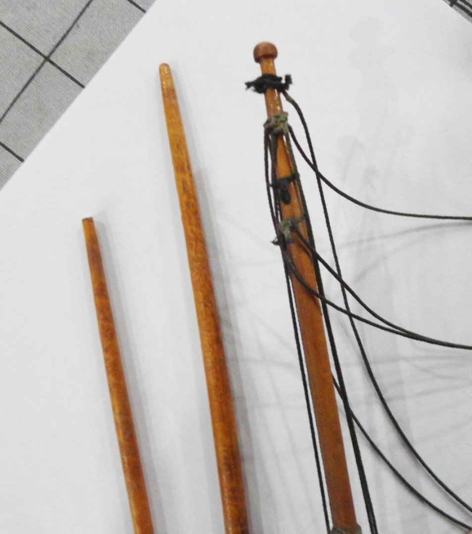
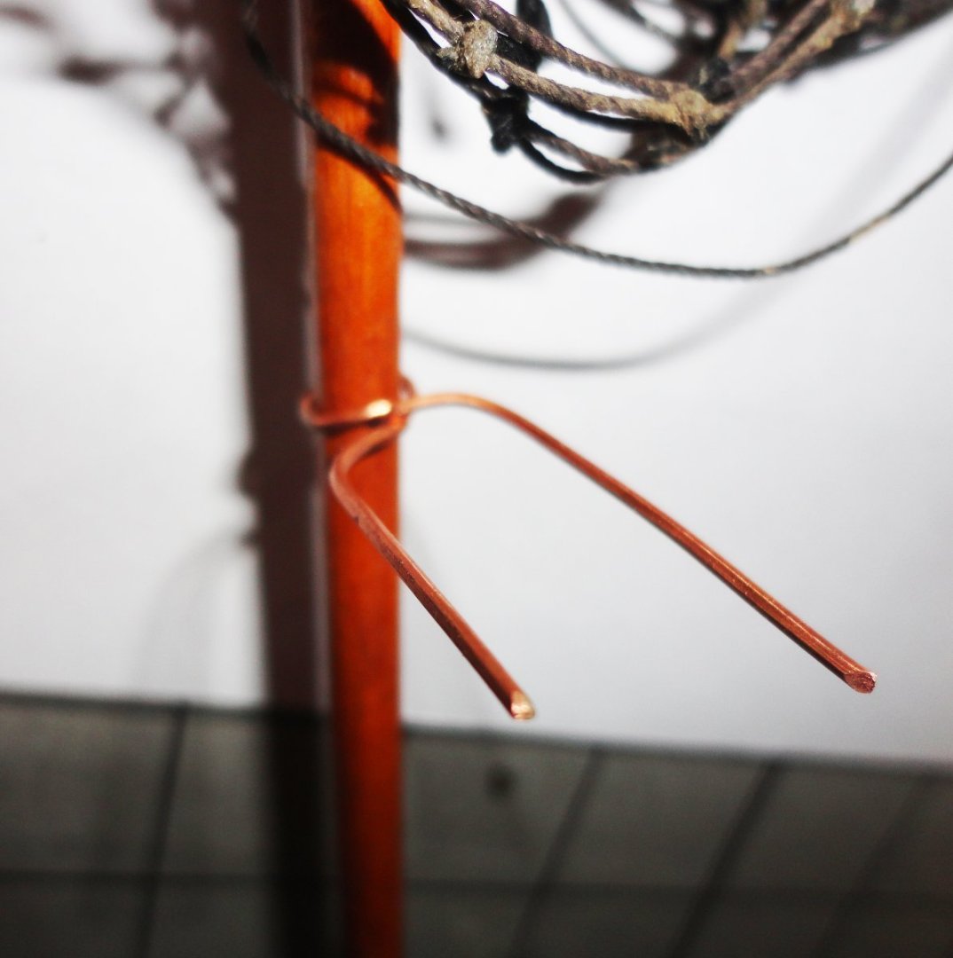
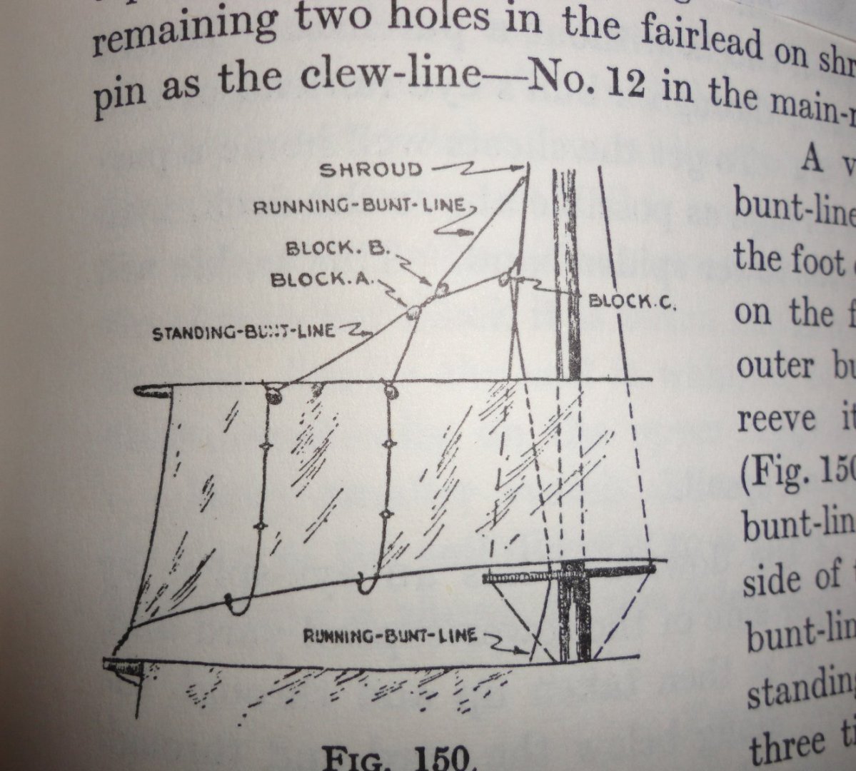
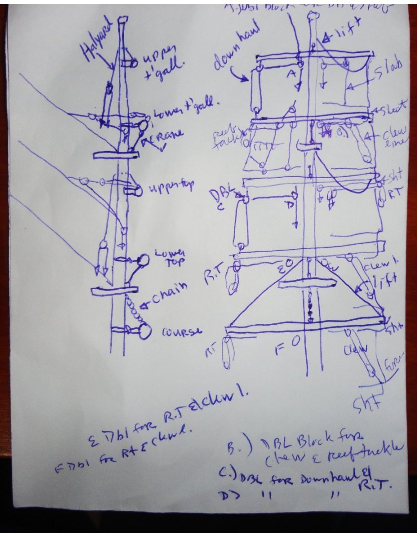
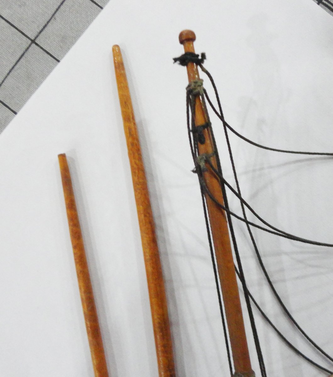
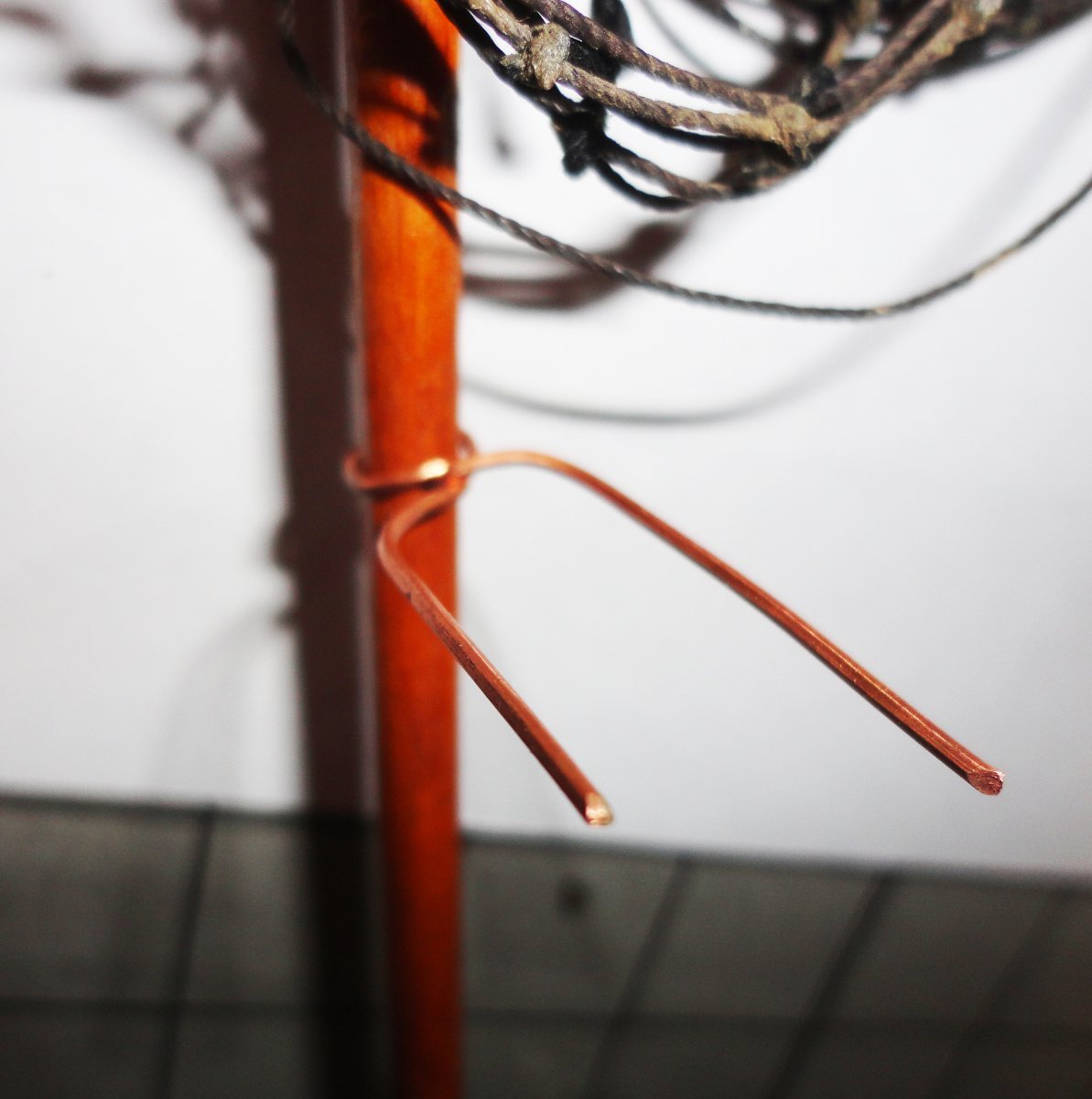
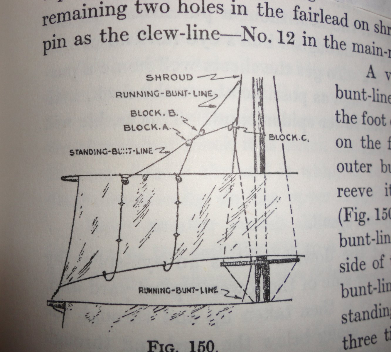
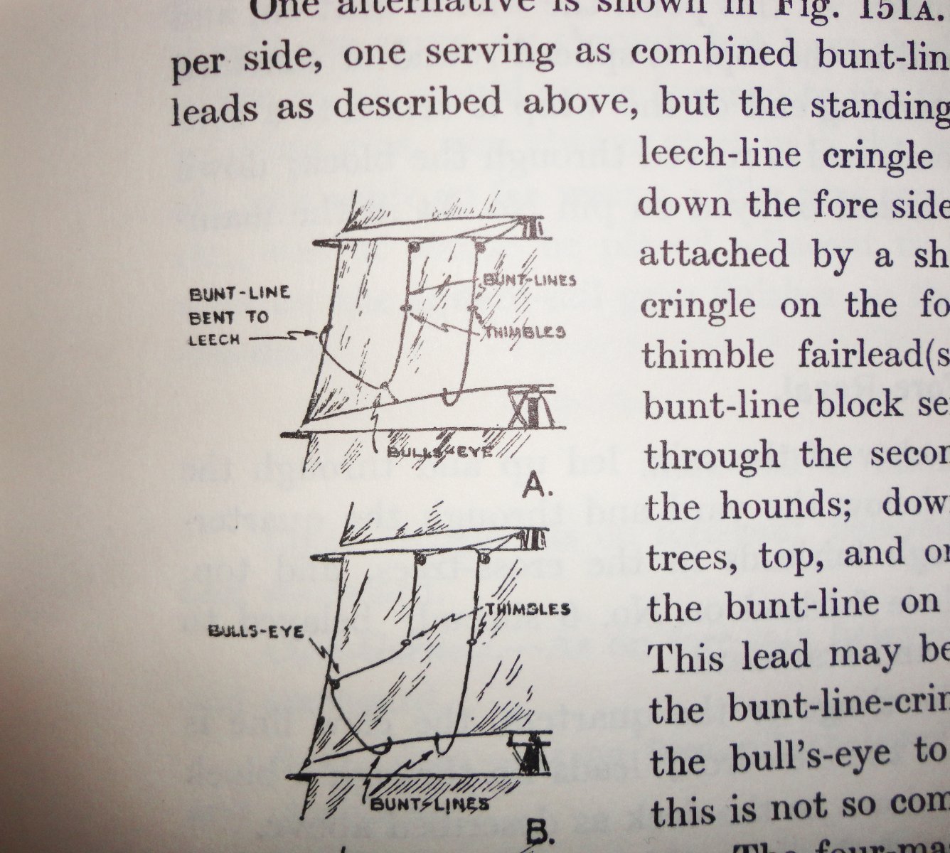
Well, George .. I've been doing a lot of thinking about this. For one thing, I'm going to have to replace all of the lines - most likely with scale rope I make on the Rope Rocket. Yes, it will be significantly reduced in thickness - but not entirely to scale. Now that the fore mast has been removed (and it proved to be relative easy to do so), I see that the upper sections are thicker than if 'true to scale' - and the yards are also thick. But is this really a bad thing? I won't replace the masting, if only because it would get too far from being a restoration. Yet a 'faithful' restoration would be to change as little as practical. I'm compromising on something 'in between'. I note that the sails are sized wrong (compared to the original ship), but those are the ones that I'm using since they cleaned up nicely and someone put a lot of work into them ... I can only hope that at some future time in my semi-retirement that I can make a Thermopylae more closely imitating the original (also with the barque rig, yet before she was painted white prior to sale to Portugal) ... see, when I saw the present model at a distance it made me think of the 'Big T' in white. I do have a photo of Thermie converted to barque rig, but still with the original hull color. Its noted that the mast I have to work with is fairly stiff and resists bending. It is probably due to being a.) made of sturdy dowel - as not all dowels are created equal, b.) is somewhat out of scale in the upper sections, and c.) is coated thickly with varnish that may add a 'monocoque' effect - not unlike early aircraft whose strength was enhanced by a metal skin over the framing. It makes plastic masting/yarding seem rubbery, as late editions of Revel and Airfix ships often turn out to be. Even the original version bend too much. I see great advantages to using well-chosen wood. The plan right now is for the course yard and lower topsail yard to be fixed (as usual) - with (for simplicity) will used copper wire bent a shown in the next pic - the upper topsail will have a yoke and parrel, then a fixed lower topgallant and a moveable upper topgallant. Sure, this isn't 'right', but its pretty much how the model was made and its the hand I'm dealt. During lunch at per-diem work today I made a crude sketch . The masting can have a hole for the halyard of the two yards that will be setup as movable. The lower topsail and topgallant yards will have a crane, and the course yard will have a chain. This will be better than just 'tying the yards to the mast' with line as done originally. The upper topgallant will have a slack lift (since it will be raised), simple downhaul tackle, no clew lines (per Underhill) and the sail will have a slab line on either side - so the blocks on the yard near the mast will be double blocks (for the down haul and slab line on either side). I want to take advantage of (as shown in Underhill) how two bunt lines can be merged into a single control line ... and also how the leech line can be combined with the outer bunt line (in one of 2 ways). This can reduce three lines (leech, bunt and bunt) into a single line to go down to the deck .. thus greatly reducing the amount of fairleads that get drilled into the top above the course yard. Now bunt block were like something like 6" blocks (150mm), so using 1.5mm seed beads (perhaps 2mm) will be adequate for these - and other 6"blocks. 8" blocks would be 2mm at 1:100, but I have some that size and appear daunting to work with - but a compromise at 2 1/2mm can make things easier. Now the yards below can have a hole drilled near the yard ends for the sheets of the sail above - routed to a double block in the center of each yard and thence downwards in front of the mast (no fairleads needed except for a couple on the undersides of the yards). Since the yards are a bit thicker than need be, I'll have to see what to do about mounting jackstays and foot ropes (not shown on the sketch). Worst case I can bend the sails to the yards as was done originally and omit foot ropes ... but either would be a nice enhancement, and practice to see if my hands can do the work. The lower topgallant is the highest sail to have reef points, but (per Underhill) being fixed it has a clew line - so the double block on the yard near the mast will be for the clew line and reef tackle. The yard below, being movable, will have a double inner block for the down haul and reef tackle. The lower topsail yard below that .. a double inner block for the clew lines and reef tackle. With these simplifications, I'm counting only 11 lines on each side that would pass through the top above the main course yard ... not exactly Swiss cheese. 'Early days yet. I figure on learning as I go (still waiting for the Seamanship manual) and solving snags or re-thinking as needed. And I also have to think about what I have to do on the hull and deck areas once the masting is cleared away. A lot of time to go in 'dry dock' ! Johnny PS ... Speaking of scale, the ship pictured below of some 450' would have about a 54" hull modeled at 1:100 ... a whopper.