Snug Harbor Johnny
-
Posts
1,501 -
Joined
-
Last visited
Content Type
Profiles
Forums
Gallery
Events
Everything posted by Snug Harbor Johnny
-
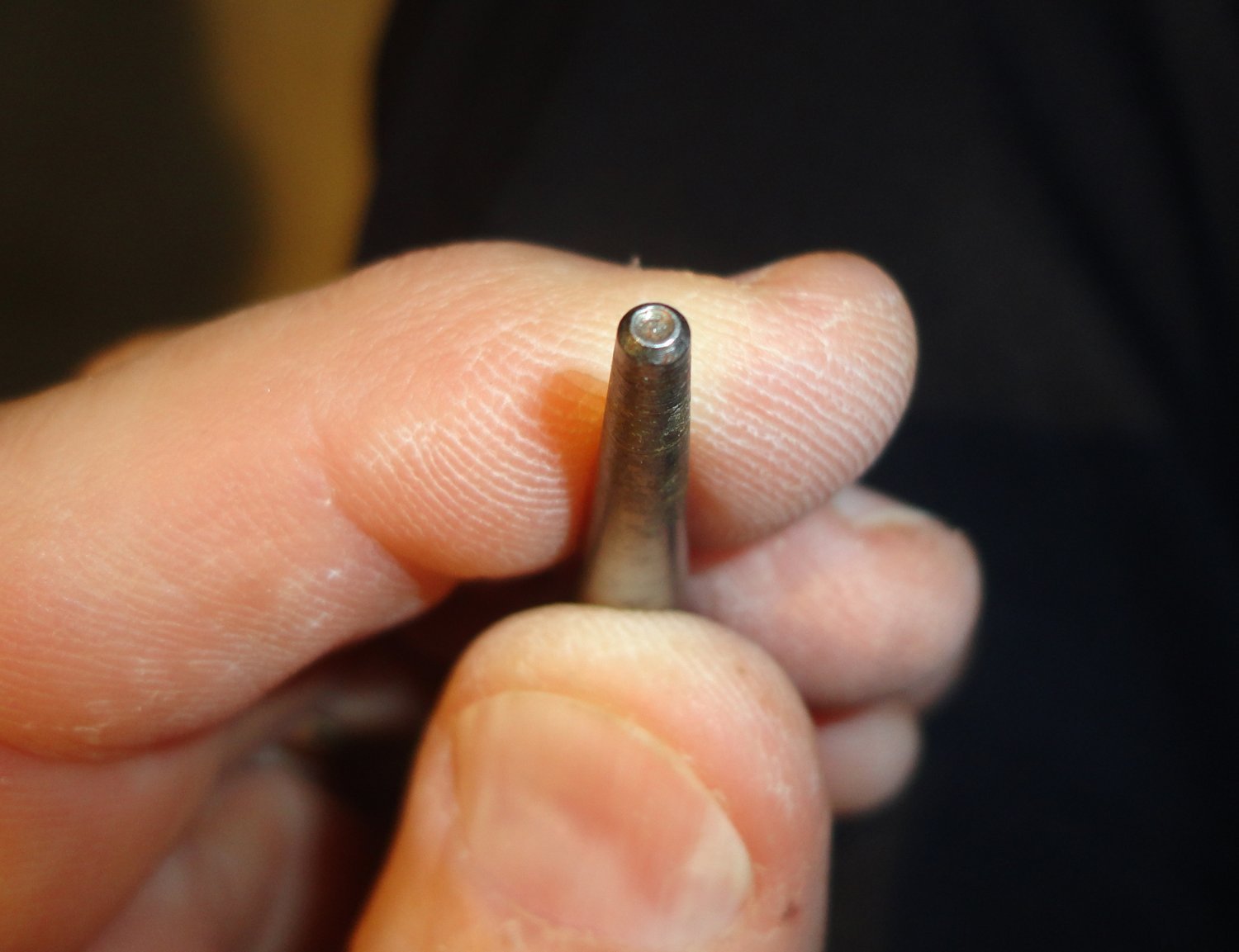
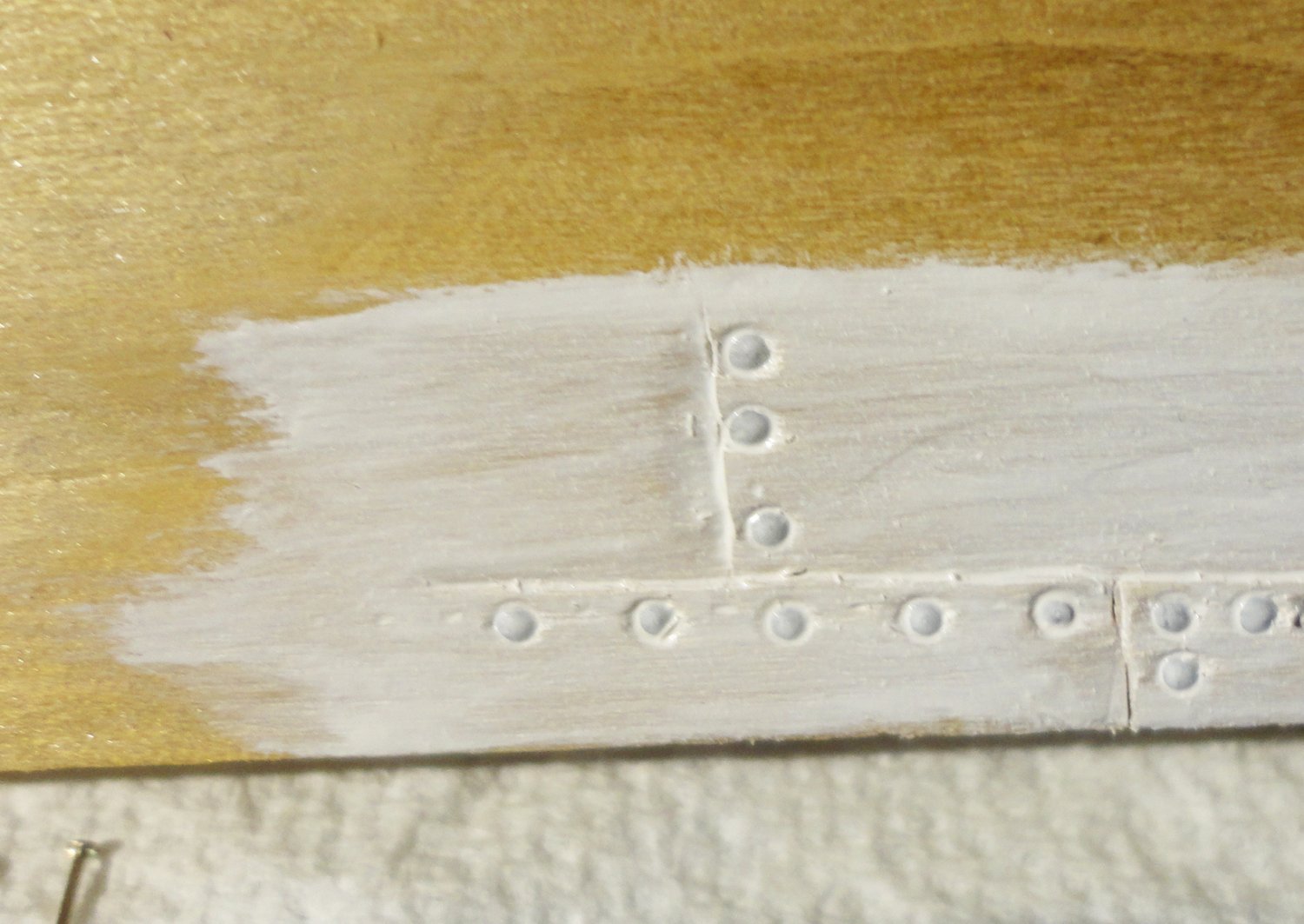
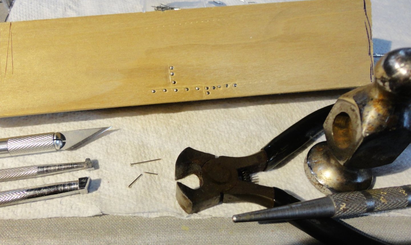
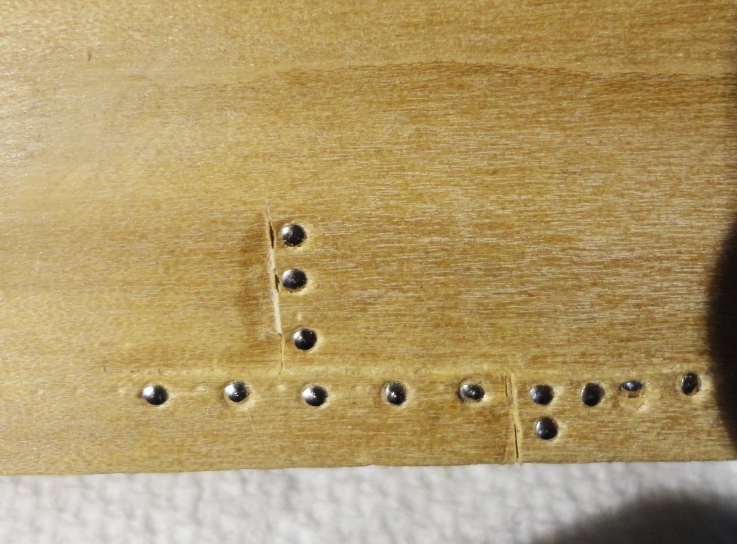
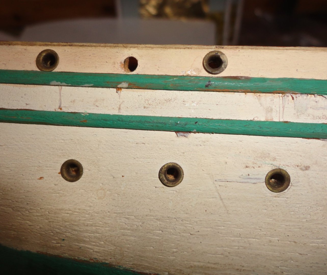
 These are points well worth noting. Do I want to save myself trouble (the imp on one shoulder), or do I want to go down a 'rabbit hole' (the Mad Hatter on the other shoulder)? A long winter looms ahead soon enough, so I'm not sure. Now there is the GF 1 riveted plate (as built, which is the model being restored) - renamed Tovarich post war, prior to some modifications - and the GF 2 of welded construction (although the weld lines show in photos of her). Below is a close shot of the Tovaricsh (English spelling) showing the lapped, riveted plates - and the rivet do indeed stand slightly proud. They are not 'domed' as seen on locomotives and other steam equipment of the 1930s, but still have a convex shape above the surface of the plate. The air ports (port holes) are nothing like the eyelets used on the model as previously advised ... no flanges are on the outer surface. If the eyelets are omitted, small 'eyebrows' could be put over the holes as seen in the photo. So to fool around with the idea of mimicking lapped plates, a piece of poplar was manipulated with the tools in the photo below. 1.) A shallow horizontal line was cut with an X-Acto, with a couple short lines at 90 degrees to the first. 2.) Small and medium leather working bevels were tapped on one side of the cut line to try and mimic lapped plates. I used to tool leather, so a light touch is needed. There is no groove, as the wood fibers are compressed on only one side of the initial cut. 3.) The smallest pins I could find at JoAnn Fabrics were 1/2" long with about .050" heads, so the length was trimmed with a cutter (could have used dikes) - but the thin soft wire shank can be cut with a beader's flush cutter. 4.) The pins were pushed part way with bent pliers (I should get a pin pusher), then tapped (not too hard) before setting with a nail-set (again, I buggers a couple learning the right amount of force to use). The sample stick is also in the picture. The test of concept was 'freehand' - no measuring or guides, so I can do better. The nail-set pictures below show the convenient concave center that nests well on the concave pin head. Now the heads are not to scale (what 5" at 1:100, versus something like 1 1/2" or so on the original), but the idea is to suggest riveted plates. Below is a close-up of the test piece. Now paint will 'fill in' some of the defects, as the first coat of some Testor's paint indicates. After drying, bit of dust and wood fibers can be smoothed away before using a tack cloth and applying a second coat of paint (not done on the sample yet). The concept looks promising, so the question is which of the 'nudges' on my shoulders will sway me ... the imp (devil) or the Mad Hatter?
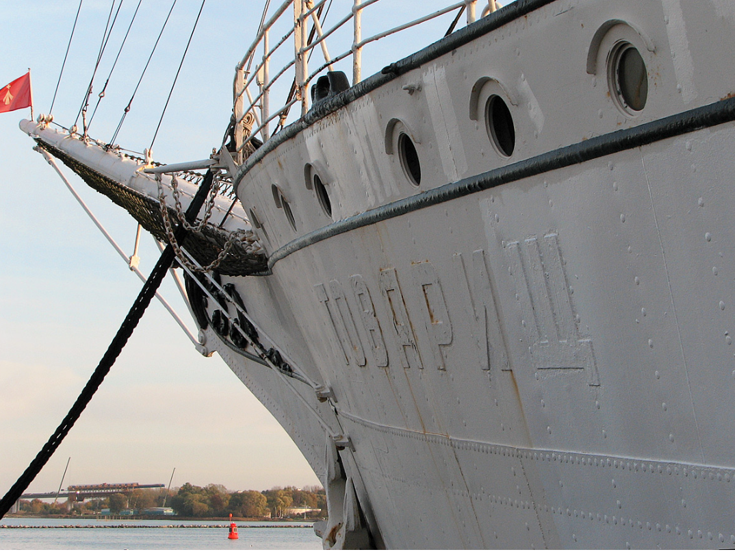


-
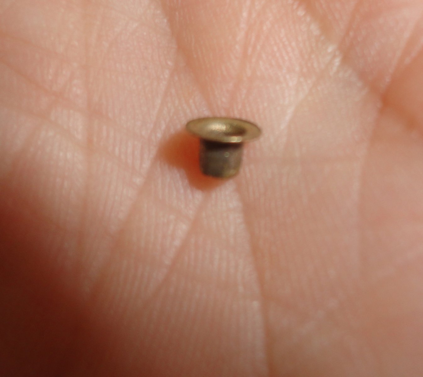
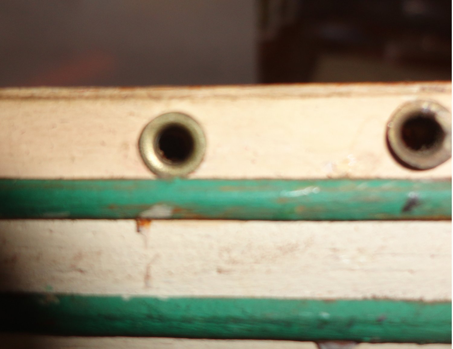
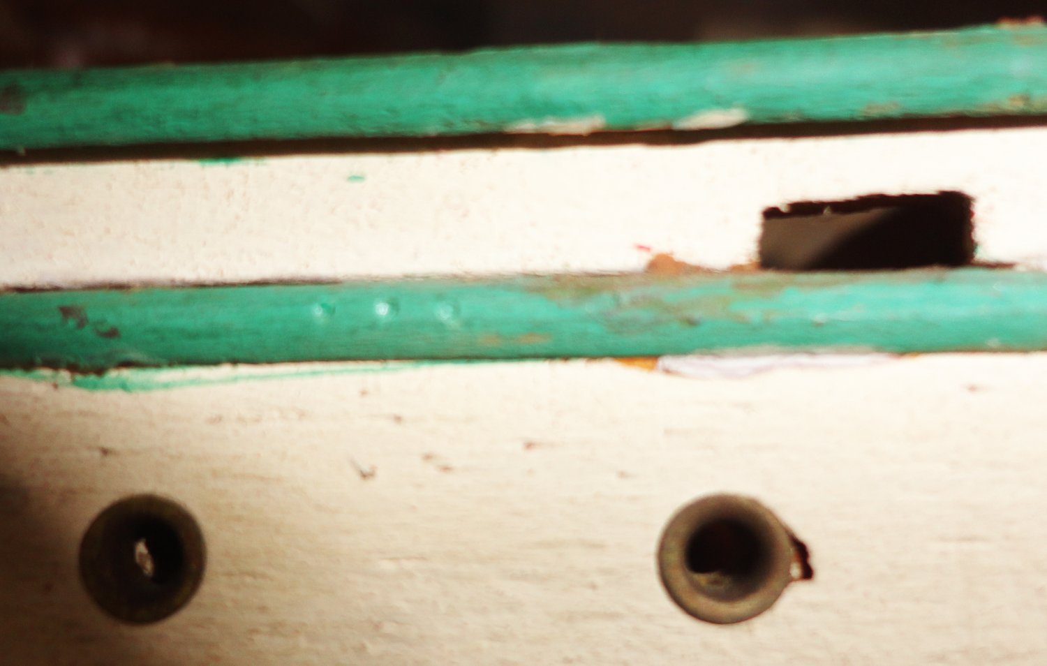
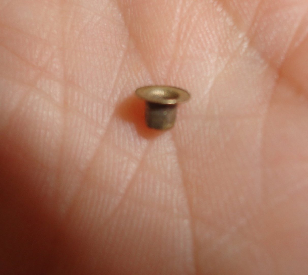
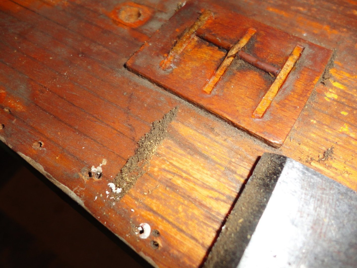
The small eyelets the builder used for the port holes can be lifted out, as they were not glued - just held in by pressure from a properly sized hole drilled for them ... and none are missing after all these years. The first picture shows one removed. A bit of grain shows through the now 'chalky' paint - I might lessen that a tad with a careful sanding rather than trying to fill. The ship was riveted steel, and would show no grain, yet the solid wood hull on the model was made as-is. 'Guess its a balance between restoration and enhancement, and I don't want to overdo anything. The eyelets have dulled over the years, but with a couple swipes of 'Nevr-Dull' treated cotton (still available) a satin brass (soft shine ?) They have a 2mm through hole, a 5 mm flange width and a 4mm height. I saw new ones available, but they'd look "too shiny", and might not have the same 'fit'. The eyelet was replaced after touching up, and it seems OK. The picture is a little out of focus. Under consideration prior to a light repainting is to scribe some plate lines on the hull, and make some small divots to suggest rivets. The next picture shows three as a test ... 'Not sure if indents will do as they can on copper plates or strips applied to coppered hull bottoms, as the small nails used on original copper plates do indent - versus the domed shape of a rivets holding plate hull together. (Welding later made riveting obsolete.) Perhaps tiny dots of dried glue could be experimented with - or tiny pin heads if they can be found. OR I can just sand and repaint. Suggestions are always welcome.


-
You're right that Bruma has an outstanding build of the CS - one I could never come close to. 'Hidden' in my earlier post today, I do mention that ironing with a medium iron (no steam) will be the next step to de-wrinkle. The Admiral assured me that the sails are made of linen gauze - something hard to come by today. Cotton would have had a much higher risk of shrinking, but with either fabric, most shrinkage can occur if one 'tumble drys' (especially with heat) - just as woolen knit-wear will also do. That's where the 'blocking' comes in. Also, if one makes clothes 9as the Admiral does), both cotton and wool from the bolt can be pre-washed to remove any sizing AND pre-shrink by tumble drying with heat. With wool, this process was known as 'fulling'. Further shrinkage of garment made with pre- shrunk fabric is unlikely. Therefore, if I make sails on a future project, I'll pre-shrink the raw material first before cutting.
-
Ahoy, Tony ! I used to like the 'Minwax of Old' for general woodworking, but it has been significantly re-formulated to comply with VOC reduction ... likely a good thing. Now, as then, it really takes 3 or 4 days to dry - and in the interim it gives off a distinctive odor - a litttle less each day. Its still good as a colorant, as I had to match some unfinished red oak stair 'bull-nose' to pre-finished 3/4" tongue and groove red oak flooring. I started with Minwax that was a little lighter (and a slightly different chroma) than the flooring, then added small amounts of artists' oil colors (thinned with a little Minwax clear). Just a little at a time to the container used for mixing enough for the need, as it is hard to 'lighten' if one goes to far. A test piece of oak was used and compared to the finished flooring (which had some color variations inherent due to variations in grade. Also I was using #2 common, less expensive than pricy #1 - yet still much better than the next lower grade.). 'Seems that Minwax is fully compatible with artist oils, and to be sure of my color (after 'force drying' the test piece with a blow dryer) a little clear varnish was applied over to get the sheen of the pre-finished flooring - and the color would be 'flat' without the top coat of varnish. It looked good, so I went ahead and treated all the bull-nose needed. One day later I applied the clear Varnish (Varathane clear - a different brand name, but also compatible with Minwax) and the next day was able to go ahead doing the landing into our sunken family room ... We can't tell that anything was matched, it looks that good. Right now, I'm restoring a very old Gorch Fock model that had the deck and masting coated in varnish 'back in the day'. The varnish prevented any dirt and grime from getting into the surface of the wood. I was able to use slightly soapy water, isopropanol and acetone (on that order) to get off all the gunk - which may have had 70 years of tobacco smoke, dust, aerosols and grime built up (especially on the decks). In fact, I used a low-angle carpenter's chisel to 'holy stone' the deck (gently, as to not compromise the original protective layer of varnish) - and I'm amazed how much stiff came off to reveal the beauty concealed below. This raises my opinion of varnish as a protectant (especially is a model will not be cased, as was the case with the one I found neglected in an antique shop). If wood is conditioned with 'boiled' linseed oil (and unless it says 'raw' linseed oil on the container, it will have a 'dryer' in it), it is advisable to mix it 50-50 with ordinary turpentine. Some woods will darken with this application, such as walnut or mahogany ... mush less so with lighter woods. If a few days go by, the turpentine (which assisted penetration of the linseed oil) will have 'out-gassed', leaving the linseed oil to cross-link by the action of the dryer. I have a tin of 'Japan dryer' (enough to last a lifetime), and am in the habit of adding a drop per half pint of linseed oil or any oil-based paint to insure good drying. Once oiled wood has out-gassed, it will accept either varnish or shellac as a top coat. I happen to like shellac (amber or clear, depending on the wood), but caution to use product no much beyond the expiration stamped on the can of pre-mixed shellac (e.g. Zinnser) - much easier than making ones own from shellac flakes. If shellac is used, it can be removed by alcohol (if needed), so future cleaning cannot be done with alcohol.
-
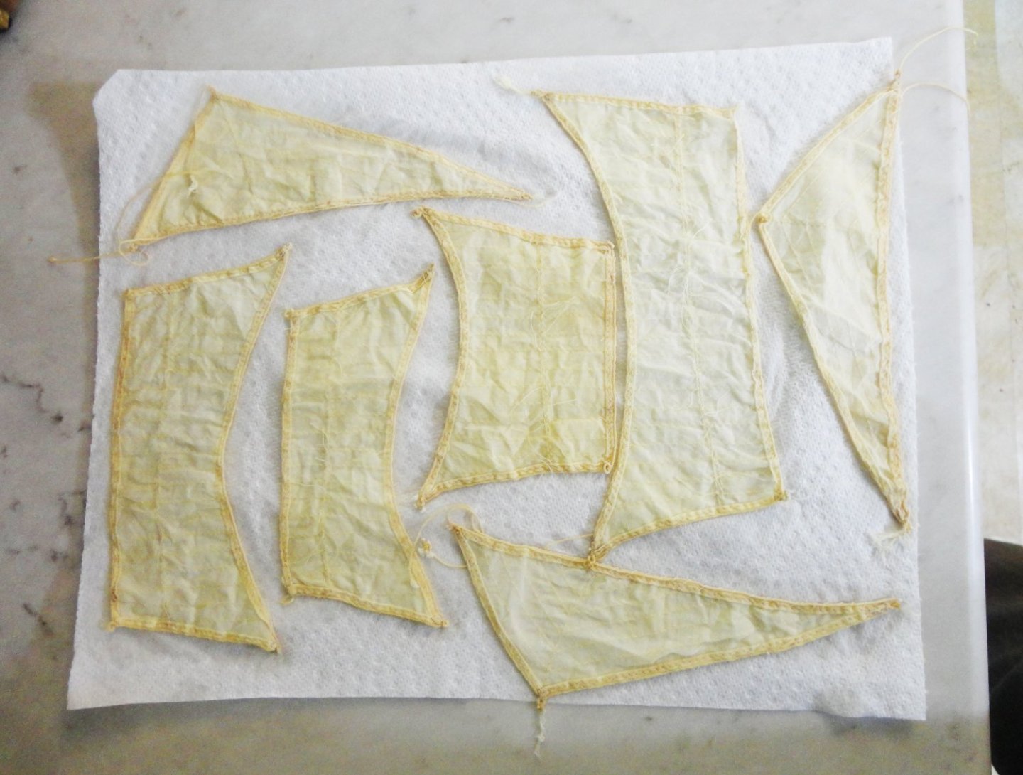
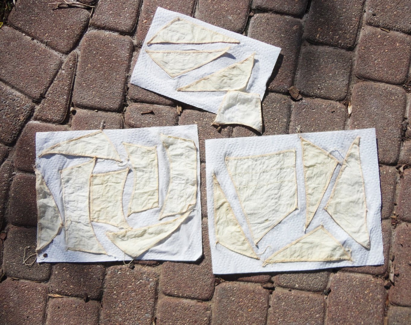
Good thought, Keith - and I had considered that as a possibility (just never said that in a post). The Admiral previously showed me how to block a knitted sweater on a towel to prevent shrinkage. By 'blocking' the sails on paper towel (with the scale being small for the sails) I figured that the roughness of Scott towel and the sailcloth were a fair match. I had to pull the edges carefully to lay them out straight and nearly taught, because that is how I got into trouble on one of the sails I did earlier (and the repair was documented). The moist material 'gripped' the paper towel and the sails dried without appreciable shrinkage. There is some puckering within the sail area, but (as done before) they get a light pressing with medium iron (no steam) - and that removes wrinkling. BTW, I thought the sails were slightly oversized to begin with, so a little shrinkage might make them fit the masts better ... but they are nearly the size they started at. And then (as before), I'll straighten and tint the reefing lines. Its amazing how much grungy yellowing came out of the sailcloth - and Beth is using the same method on her antique Galleon sails.
-
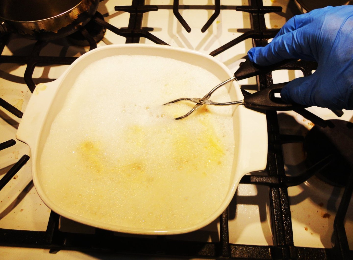
Thanks, Keith. I think its just fine as far as I went ... no use overdoing anything. So today (after more garden stuff ... this ideal weather PA is having will only last so long) the remaining sails were treated with Restoration. With confidence (and careful handling) I did the step 1 rinse in hot tap water, then did 3 successive baths with the cleaning product. Ceramic cookware was half filled with hot tap water, then heated to approx. 160 - 180 F on the stove, shifted over to a cool part of the cooktop, some rinsed sails added and a scoop of product - stirring with metal (stainless) tongs. It really foams up a lot, and if there is too much water to start with there is a danger of the foam going over the top (my first batch threatened to do that, so two pieces of paper towel were put on the foam to 'soak up' and break the bubbles). After 5 minutes (or so) the hot pot was moved with pot holders to the sink, and cold water run in. My gloved hand scooped the sails out and rinsed under cold tap water. Then I 'blocked' the sails on paper towel, covered with more paper towels and hand pressed. I have other 'irons in the fire', so rather than get the blow dryer, I took the blocked sails outside to get sun-dried ... The dirty, old sails (likely starched originally as previously noted) now have a new lease on life. Fragile when wet, they firm-up once dried. I treat the reef points as already pictured, then pick something to do next - probably do work on the hull. There is not enough space to install 'eyebrows' over the top row of portholes, so that, as well as any thought of simulating rivets should just go out the window. I might consider replacing the eyelets used as portholes - as conceived by the original builder. That will make repainting the hull easier, as it really does need repainting.
-
Super tip, Sal ! I will definitely try this block-sanding jig to make use of some "ordinary" blocks I have lying about. Of course, once Chuck is re-stocked is fabulous array of CNC made blocks I'll likely order some. Yet even those might benefit form just a few seconds in the sanding canister - with very fine paper.
- 144 replies
-
- 4
-

-

-
- Harriet Lane
- Model Shipways
- (and 1 more)
-
'Nice ship's wheels. 'Saw recently that a ten spoked wheel is needed for OcCre's Endurance (another fine build).
-
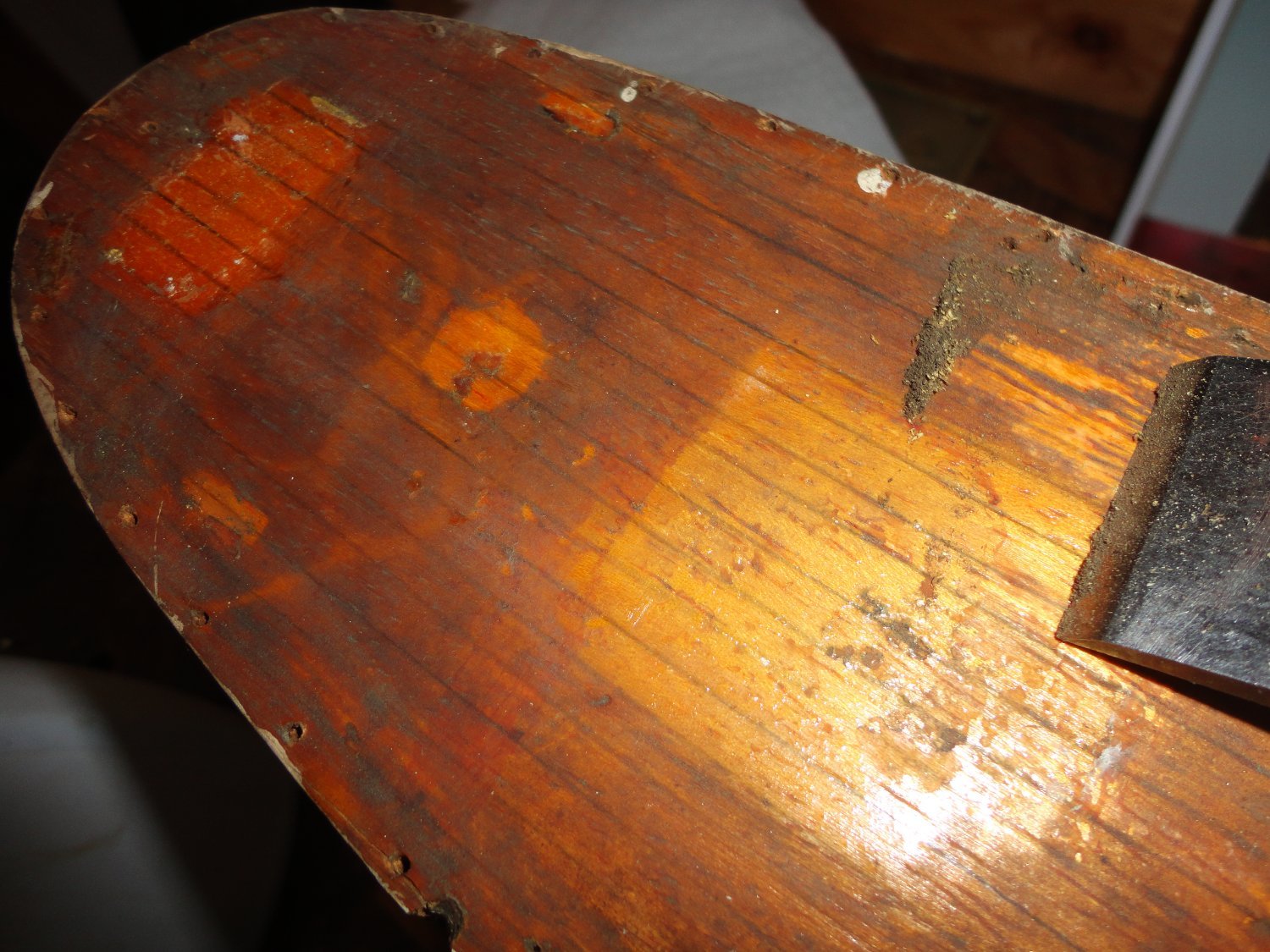
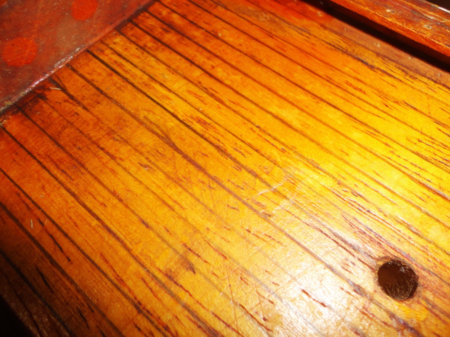
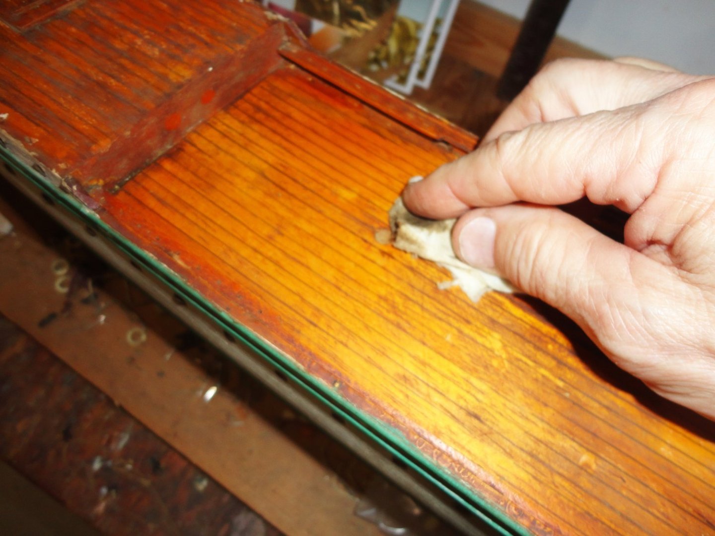
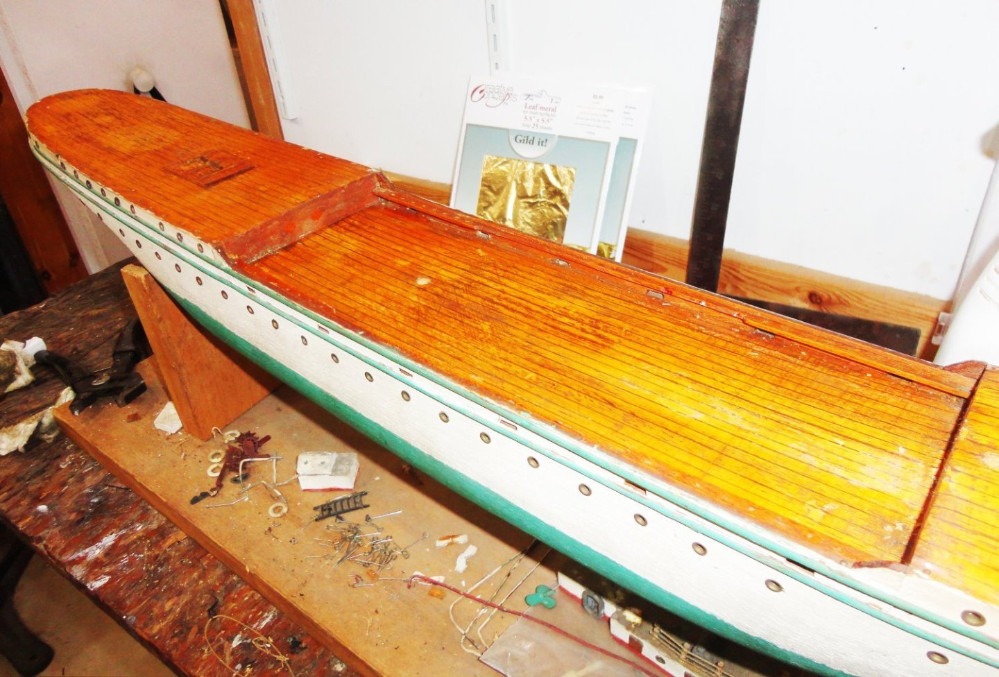
'Thought I'd start with a gentle cleaning with water plus a little mild dishwashing liquid soap ... hey, if it can be used on ducklings, why not a deck? There was obvious dust & grime picked up on the bunched paper towel used, but left on the deck was a grunge that didn't readily come off. To the touch it was slightly tacky, so I let most of the water evaporate and tried to use a flat, low-angle carpenter's chisel (carefully) with short reciprocal strokes ... and a bunch of stuff started coming off ahead of the blade - revealing more of the underlying inked (or penciled - not sure) and over-lacquered plank pattern. This might be compared to 'holy stoning', except on a model. The idea is to skim very lightly without compromising the original surface underneath. No way did I want to cut through the lacquer and expose bare wood. The hull has a nice 'heft' to it, and might be maple (heavier than pine). The next picture is a close up of the process. All the eyes and railing nails were pulled before beginning, and the nail holes are oversized for the nice 3D brass stanchions procured to replace them. The solution will be to glue round toothpick ends into the nail holes flush with the deck, then drill what size is needed for the replacements. So far, so good. Since it was already determined that lacquer was used (rather than shellac - which alcohol would attack), I decided to try rubbing with denatured alcohol next. Having worked with both finishes, I knew that lacquer would not be dissolved by the methanol. This time more grime was removed, but not completely, and the methanol flashed-off fairly quickly. The next step was to use acetone (sparingly), and with the right pressure applied in the direction of the wood grain, most of the accumulation or 'whatever' did come off. There was only so much it was safe to do, and the object is to restore - not strip. I thought about it, and don't want to make this model something its not - so enhancements will be limited. The rigging will be done better, as that is something I wanted practice at - but I can still respect the original modeler's intent. Below is the cleaned deck - the lighter area on the right is where the main cabin went, and fortunately it 'popped' off easily - being glued apparently with wood glue to the previously lacquered deck. The orangey cast is how my cheap camera depicts some areas, but it is not quite that orange in real life - more of a yellow orange. A close-up is added to better see how it looks. Maybe the plank lines were just penciled.


-
This is, I think, as good as it is possible to build this kit. Great job, mate! I like the way you use brown lines in the rigging throughout. When I get back to mine, such that it is, the plan is to use shades of brown and no black at all.
-
I've read about the lessened casting quality in MSW logs. I suppose one could spend the better part of a year going over each piece with tiny files and dental bits in a variable-speed rotary tool to 'clean them up' considerably. Then after some cerium oxide polishing, one could get them gold electro-plated (the platers might have to first nickel plate). Now THAT would really 'pimp' your model quite a bit, but at a considerable cost - possibly nearly that of the kit itself. But if you're going to spend the next three years doing a super job on this historic ship (some say the costs of building it were a significant factor in causing the English Civil War), I'd consider it. 2nd option might be to try and locate a 'classic' old Sergal kit that has the much better yellow-metal castings (which would plate better). Using the best of all the materials and plans could be helpful in the long run. Hmmmm, just had a thought ... If the SoS was the 'ship that caused the English Civil War', then the figurehead casting of a mounted King vanquishing another King might be taken (in hindsight) as Charles the vanquishing himself, as his head eventually 'rolled' when Cromwell had Charles beheaded. I see you're in Sweden, so am supposing that many there have done the Vasa - (I'd love to visit the Vasa museum some day, and also see the Oseberg ship - among other excellent Viking artifacts ... yeah - smorgasbords and saunas might be nice to do as well, I mean, as long as I was there.) The Sovereign of the Seas is a worthy project indeed. Good luck !
-
Help with these clamps
Snug Harbor Johnny replied to Some Idea's topic in Modeling tools and Workshop Equipment
I did some planking using "1 minute" epoxy and used 'finger clamps' ... that is, I held the plank in place with both hands for the 1 - 2 minutes while it solidified enough that the mostly pre-bent plank held fast. I either listened to music or sometimes had a movie on. The mixing technique for just a dab of part A and part B (one gets the knack of squeezing out equal parts on a piece of scrap lumber as a mixing board), then 'patting' and swirling this amount with a forefinger tip until the temperature is felt to be rising (meaning the epoxy is 'kicking'), then dabbed to the places on the bulkheads (frames) where the plank is meant to go, wiping the excess off the finger applicator on a shop towel, then "clamping" the plank in place - usually not more than a minute. -
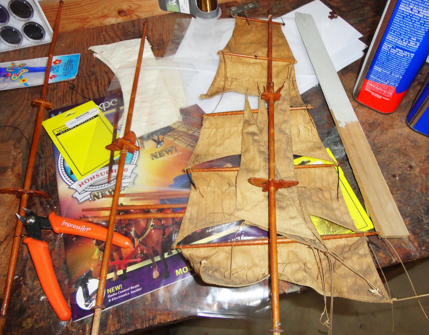
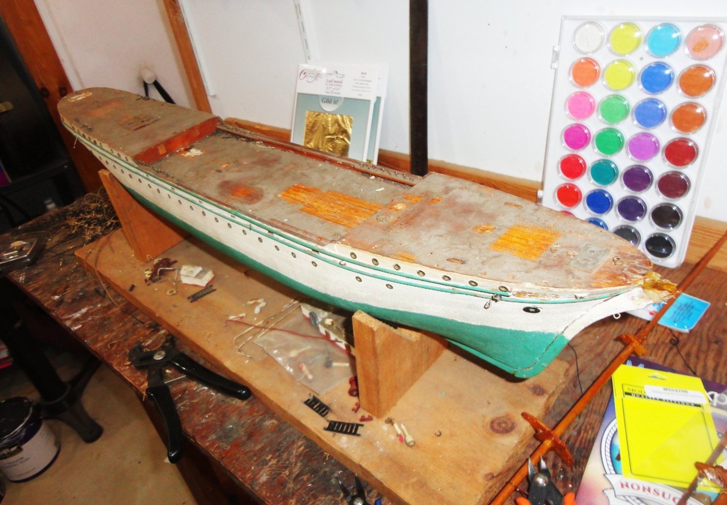
I decided it was time to 'clear the decks', so detached the remaining rigging - all really too old and not salvageable. Most the 'fittings', such as they are, are molded of a flexible substance - sort of like a pliable rubber - and only some are usable. With just a little twisting (gently) the main and mizzen masts came out of the hull, and as previously noted - this is a good thing. In the photo below the hull reminds me of a poem, 'The Wreck of the Hesperus' ... 'We're lost,' the captain shouted as he staggered down the stairs. There must have been some airborne particles raised, so next time I work on something old and dirty, I'll wear a mask to limit nasal congestion. The next step will be to see how it cleans up, then decide what work is to be done on the hull. The portholes on the original have narrow 'eyebrows', so something could be fashioned from some square wire I have. Hmmmm, wrapping the wire around a core will produce a uniform coil, from which the semicircular 'eyebrows' can be released with flush cutters - and they will all be the same size and ready to CA onto the hull above the port holes. Some repair is needed here and there on the proud railing on the sides. Perhaps rivets can be simulated (before repainting) with pinheads? I have to restore the remaining sails as already pioneered. A new stand is needed, then I can start looking to rebuild the deck structures. Below are removed components.

-
The store's location looks drivable from the Philly suburbs - maybe 2 1/2 hours. If I accumulate a shopping list it may be worth while to go there. The black-glued ship decking is likely done by 'sandwiching' sheets of basswood with a thin layer of dark bonding material between the layers - then pressing the stack while the glue cures. The resulting slab (3" thick) is turned on its side and the decking sheets planed off (0.50" thick) like flitch-cut veneers. There may be places here and there where there is a little glue penetration into the wood (depending on the peculiarities of how the grain ran in the component sheets), but the look at a distance seems great. I'd want to go there and see the sheets first-hand before laying out $25 per sheet.
-
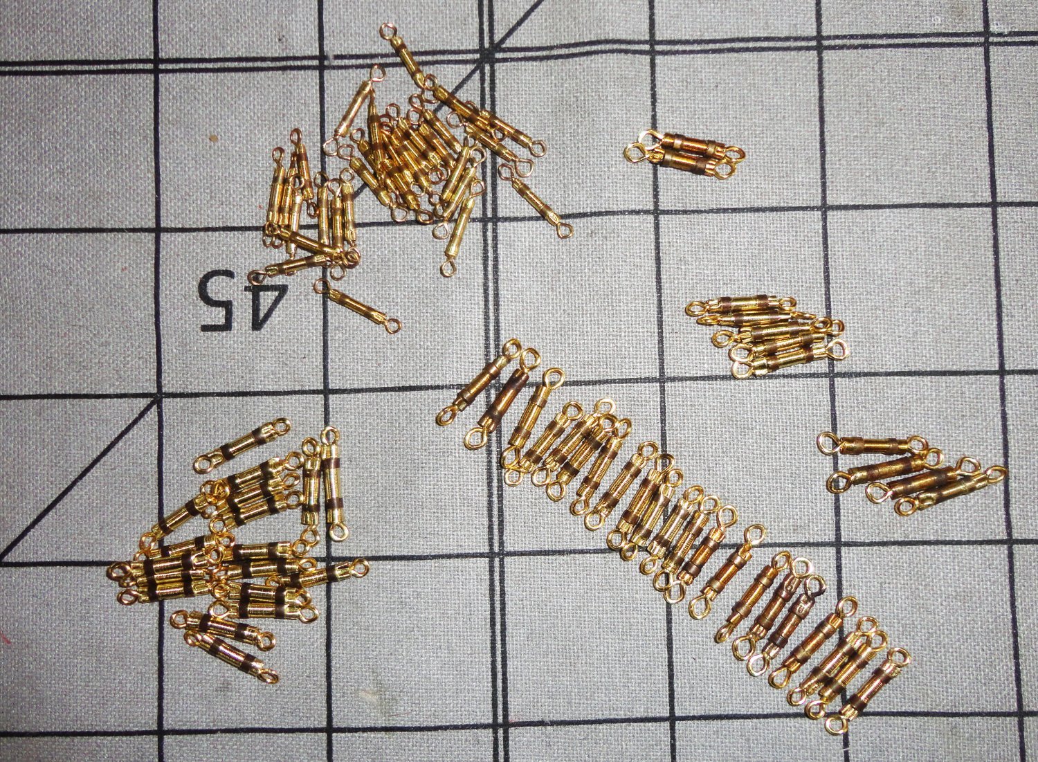
Ahoy Beth, The method I used to restore the old sails to near whiteness (but they are by no means 'bleached' - just a tad off white, which is what I wanted), will likely remove decoration not woven in, embroidered on or otherwise achieved with a permanent dye. Once again, a picture of the marked sails you are worried about can be worth many words. At last I've done enough turnbuckles in the two sizes need to think about what to do next on my restoration. There are still many things to do around the house and outside before Fall really sets-in slows progress. Doing the turnbuckles was not so tedious once a method was worked out and a few made for practice.

-
What a nice subject to build. Its not too far removed from the Gorch Fock, except the latter has turnbuckles instead of deadeyes - which I'm fabricating myself for a restoration project. I'm also on the lookout for photos of the GF1, as opposed to the later re-make - both ships survive.
- 123 replies
-
- 3
-
-
- Le Pourquoi-Pas
- Constructo
- (and 1 more)
-
My 'dream trip' would definitely include stops in London (V&A), Paris (Louvre) and Amsterdam (Van Gogh Museum) to name a few - but a tight budget and inclination (we are fretful homebodies with plants, parrots and other commitments) mean we will remain 'armchair' companions on Rick Steve's televised world tours. Gosh, its funny how one word can bring something back to mind - long covered in dust - in this case Oslo. There was a mock rhyming feast-Saga titled the 'Thong of Thor', based on the premise that Thor's hammer did not magically return to his hand, but was attached by a long leather thong to his belt. One tug on the lanyard would bring the hammer back after it was hurled. Lets see, it went something like this ... In days of yore the Norse God Thor would run around creation, And drink a pint, then slay a giant and save the Nordic nation, Or kill a worm to watch it squirm and vainly try to fang him, Or lock up Loki in the poky and on the noggin bang him. Once he did brawl through Thurdvang hall that on a trip he'd wander, In a disguise from prying eyes, in Midgard way out yonder. So all his slaves and Carls and knaves packed up his stuff and gear-o, And off they strode on Bifrost road, the perfect Arian hero. In Midgard land he joined a band of hearty Viking ruffians, And off they sailed, and rowed, and bailed among the awks and puffians. Each foreign beach that they would reach they stopped to rob and plunder, Each Nordic brute got so much loot their longship near' went under. But though they rolled in coins of gold they had one joy forsaken, For on each raid Thor's party made, no women could be taken. Each drab and queen fled from the scene when Viking sails were sighted, And Thor felt needs for certain deeds that had gone unrequited. Thor's brows were black as they got back to Oslo's rocky haven. Unto his crew he said, "Beshrew me for a Frankish craven, If I don't wrench some tavern wench, or else may Frigga damn her." Replied one voice, "You've got first choice. You've got the biggest hammer." Into an inn this crew of sin after their great landing, Each tavern maid was sore afraid of pirates of such standing. But golden coins warmed up their loins, and soon their ale ran free. Thor's motley crew poured down the brew and made an all night spree. Thor's glances strayed unto a maid with hair as gold as grain, A lisp so shy, a downcast eye, and not a trace of brain. He swept her charms into his arms and to an upstairs bower, And did not rest or give her ease the whole night plus an hour. When Thor got up to drain a cup, she looked like one near death, Her limbs were weak, she could not speak and only gasped for breath. "You ought to know, before I go, I'm Thor !" he bade adieu. "You're Thor?", said she, "Conthider me, I'm thorer thir than you!"
-
Old eyes and shakey hands needs some advice
Snug Harbor Johnny replied to David Rice's topic in Wood ship model kits
One idea: Pyro (also sold under the Lindbergh brand) made a 1:163 plastic model of the steamboat Robert E. Lee. Since the original was close to 300' (high 200's, but I don't have it memorized), what might seem a 'small scale' has about a 21" hull - nice sized for a model. There is a detailed build (with some 'busts') of this kit on MSW for you to review, and also a laser-cut main deck available from HIS models (a Czech company I've used a couple of times). Additionally, there is a 1970s Scientific model in wood at the same scale (I have both kits in my stash) with printed decks (saves the trouble of planking) included, plus a mahogany finished base for the project. There is a contemporary kit that's around 1:130 - much bigger and costs more. There's a build log of that on MSW). This subject vessel (some old images are viewable on the internet) has some nice details, but there are no guns (and all the fuss that goes along with them), no masts & spars (and all that associated rigging, deadeyes, chainplate, etc.) and no copper plating. Just some guy wires and some minimal rigging for the gangway and life boat. Neither of the 1:163 kits has to have the hull planked. I have seen both these kits from time to time on Ebay (sometimes in multiples from U.S. sellers), mostly with a 'buy now' option that I'd recommend. You can check out as a 'guest', so you don't need an account or need for international mail. Why did I get BOTH ? Some of the details in the Scientific kit (which is a good kit BTW) have to be semi-scratch built from wood stock provided, and other details are out of treated card stock of some kind. The plastic kit has nice molded components that can simply be incorporated in the the Scientific build; like the boiler and piping amidships, the fully rotating paddle wheels (much superior to the static, partial segments Scientific has), the fancy tops that can be put on the wooden stacks and other details. Everything gets painted, except the main deck. Yet most of the Scientific kit have the heft and appeal of wood, which I find pleasing. You only live once, and your modeling skills may decline sooner - so spend a little (and these are not expensive kits) and build on your own schedule. My manual dexterity is still at about 80 -90%, but i found that my memory was the second thing to go. What was the first? ... I don't remember. -
Would you buy pre-owned wooden kits?
Snug Harbor Johnny replied to Frank Burroughs's topic in Wood ship model kits
I'll second all of the above, however I've picked up a couple pre-owned 'older' kits - some of them either partially built or 'missing some items' - to use for some of the materials and fittings. If you can find something like that at a flea market or garage sale (being able to have a look at it) inexpensively, there may be deadeyes, 'good enough' blocks, various sizes of wood stock and doweling (sometime these are pre-tapered for yards - a great convenience), and various fittings that may include pins, ladders, ship's boats, gratings, etc. And sometimes the rigging rope is OK. There is another twist in the 'old kit' and 'plastic v/s wood' scenario, and there is at least one example I found and have acted upon. Having reviewed a couple Robert E. Lee builds on MSW (and it is a fine subject not having canon/gunports or complex masting and rigging to do - but there are other 'fiddly bits'), I bought an old, unbuilt Scientific kit on Ebay that had a buy-now price (not uncommon). These come up regularly, and there were several on Ebay when I was looking. I was happy with the kit up-on arrival, and it is in my stash for a future time - unless it ends up in my estate, but I don't mind just looking at it (or even thinking about it) from time to time - as I like to occasionally open and examine everything stashed. 'Funny thing about the Scientific kit, is that there is no 'stated scale' on the box ('can't forget if I did a kit review or not, but elsewhere have noted this feature). So I measured the wooden hull pre-form and calculated that it was about 1:163 compared to the stats for the original hull length. THEN, a Lindbergh kit of the same steamboat (also sold under the Pyro brand) turned up at a rock shop adjacent to an Allentown, PA area cavern that had a tempting price on it ... it looked like a number of plastic models from someone's stash had ended up there. The box scale was 1:163 ! So I bought the kit on speculation that it was close enough to the Scientific kit to used some detailed plastic parts instead of having to effectively 'scratch-build' them on the wooden model. As luck would have it, the plastic hull was the same length as the wood. Having much of the kit built from wood is much better than just building it in plastic - although some have bought laser-cut wood decking from HIS models for the Pyro/Lindbergh kit, but this only covers the main deck and not those above. Using the plastic molded boiler and piping when the Scientific kit gets built will certainly be more convenient than near-scratch making from cunks of wood and dowel. The Scientific kit does not have rotating paddle wheels - just partial segments that project below the wooden covers. But the Lindbergh kit has fully rotating paddle wheels that can be incorporated into the Scientific model, that will have the wooden housing built over them. The turned wooden stacks in the Scientific kit are preferable, yet the fancy molded stack tops from the Lindbergh kit will be better than cutting them from the stiff paper in the Scientific kit (or trying to make then from brass stock) - and the tricky pair of braces that go in between the stacks may be easier to do with plastic parts ... it all gets painted. I could go on, but its safe to say that "melding" both these kits will give me a result better than with either one alone ... a happy marriage of wood AND plastic. -
Thanks, Noel. Obviously I've suspended the Vasa build for some time, but hope to get back to her in the New Year. (Right now I'm trying to restore an old Gorch Foch scratch-built model I came across in an antique shop - and learn some about rigging a clipper in the process. That and a partial log of busting a Great Harry model don't appear on my signature as I don't want the signature to get too long or bogged down stuff.) As the Vasa log points out, there are MAJOR problems with the old ca. 1960's version of the kit at 1:100, and my efforts are to try and make the best of the 'sow's ear' and end up with something that will be recognized as the Vasa in 'standoff scale' ... in other words, don't look too closely. The Vasa kits available today are FAR better in that a couple are somewhere in the 1:70 to 1:75 scale range (much easier to do the detailing than at 1:100), and one is a little larger (1:65 ?). They all have molded figures (some plastic, some cast metal) to go on the ship ... and there are MANY of them, whereas mine had no figures at all, a well as relatively crude printed outlines on mahogany sheet stock ... some very difficult to cut out and not really suitable to use anyway. I'll use a variety of little military figures painted to 'resemble' earlier period people ... These figures in no way conform to those on the original ship and will be fewer in number, and only in approximate locations. I just want to try and save what I can of something started in my teenage years, and end up with a partially rigged 'ship still under construction' well prior to its launch. If I ever go on a European vacation, I'd LOVE to see the Vasa museum in Stockholm and the Oseberg (when put in the new quarters planned). Smorgasbords and saunas might be nice also.
-
Your inquiry had me searching for a Revell Kearsarge build log ... but I did find one for the Alabama from the Revell kit 'bashed' for better conformity ... CSS Alabama by Jonathan11 - Revell - 1/96 scale - kit bash 90% historical accuracy Looking at the Revell hull of the above build, the bow shape is definitely curved - much like the 'Aberdeen bow' of the clipper Thermopylae - and not like the 'sharper shape' noted in pervious posts on this thread that the Alabama had. These posts also note the more 'angled' stern of the Alabama, versus the more upright stern profile of the Kearsarge. For comparison, Revell made a pretty good 1:96 Cutty Sark hull (with sharp bow and upright stern) that was used for their 'clone' kit of Thermopylae ... Unfortunately, the 'Big T' had a curved bow and an angled stern, so their clone is inaccurate not just in those easily spotted areas, but also in the hull lines - which are not as easy to spot. The conclusion is that the Revell hull is pretty good for the Kearsarge (with curved bow and upright stern), but less so for the 'cloned' Alabama. It is easier to file or grind away surplus plastic than to build it up in layers. For a Thermopylae clone, the sharp bow can be rounded easily enough, but the angled stern would have to be modified by building up (permanently bonding by glue, which 'melts' (welds) plastics together - then outgasses to regain solidity) - then modeling by filing/grinding to get the desired profile. If course, there's not much that can be done for hull line differences elsewhere. So the Revell Alabama clone would have to have material built up both at the bow and the stern - tricky to do, which is why the referenced build just ignores these two areas and focuses on everything else that can be done. Most likely, the Revell Kearsarge hull is closest for that ship. Not being an expert, I can't say just 'how close' - but likely closer, but definitely closer that using the same hull for Alabama, which is what they did because it would have been too expensive to make an entirely new injection mold for the second kit (same thing withe the two clippers).
-
When I count up the number of square sails on an extreme clipper - 18 if one is not including 'sky sails' (or the fabled 'moon sail') - and multiply that by 12 (an average of 4 bunt lines per sail .. more below but fewer above, plus 2 sheets per sail, and 2 - either clew OR down haul - lines per sail, 2 luff lines and 2 braces), you get something like 216 lines if one want to "fully" rig such a ship under sail - and thats just for the square sails. Now add 8 halyards per mast (24), outhaul inhaul and sheets for 9 staysails (27) plus at least 6 lines for the spanker and the total is at least 273 separate lines that need belaying. Of course there are a few that I've overlooked ... and that is why I've decided to simplify (somewhat) how I'll rig my restoration of an old Gorch Fock model to reduce the amount of "spaghetti". No wonder the popularity of "harbor rig" of a ship where the sails (and their lines) have been taken down to represent a vessel held in port for long enough to take the sails down. One can get by with sheets, clews, halyards and braces - and you can get the number of belayed lines down to 150 or less ... still quite an undertaking.
-
Its great to see the thought and detail you are given to the area under the forecastle deck. The photo Jorez posted may indeed be the starboard side of a 'typical' windlass of the time, which would look the same on the other end of it. Since the area we're talking about is mostly inclosed, I'd say that any suitably sized windlass (either form another ship model or perhaps can be found found under accessories sold somewhere) would suffice. BTW, I like the look of brass on a model - whether 'correct' or not. And brass will slowly get a brown patina over the years (might take 3 or 4 decades for the full effect), but I'd like to think that someone might be keeping the model long after I'm gone.
-
I did both Revell kits in my teens (neither survived as they were not cased, nor was my craftsmanship that good). There are a number of builds on both in MSW, which are great sources of info to make the build go smoother and perhaps expand on what's in the box (a 'soft' kit bust). Later versions of these kits will tend to have more flash and less definition - and on some case more 'rubbery' plastic. Having the masts bend under rigging pressure seems to be the main thing to avoid. Doing the shrouds (less ratlines, which can come last) and forestays from the deck up seems to increase rigidity, but things can still get dicy at the topgallant mast level. Some have substituted wood where possible for thinner mast sections or yards.