Snug Harbor Johnny
-
Posts
1,501 -
Joined
-
Last visited
Content Type
Profiles
Forums
Gallery
Events
Everything posted by Snug Harbor Johnny
-
 Not to worry ... you can always clear cookies from your device, and thats not a bad thing to do every so often as a matter of course.
 -
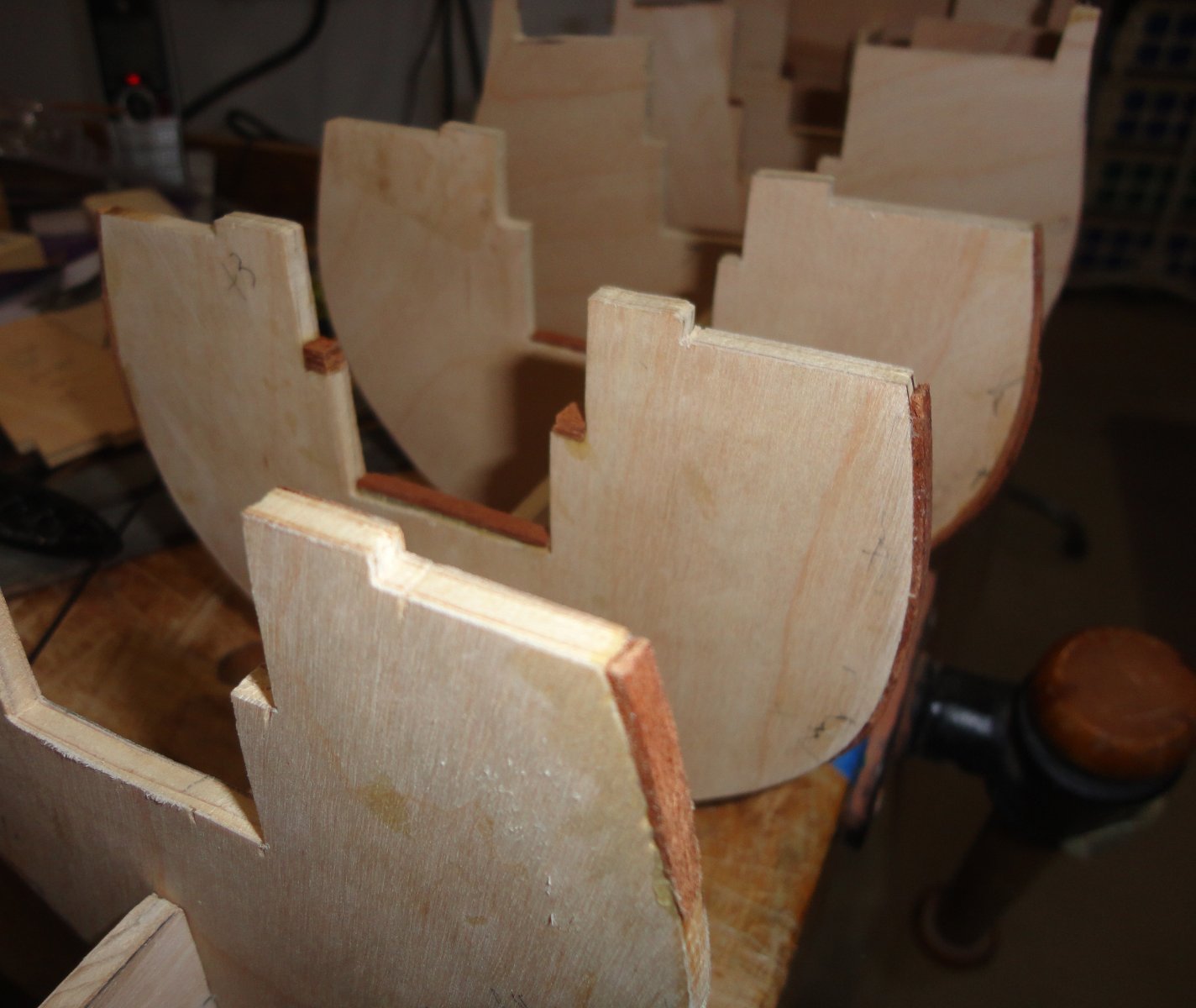
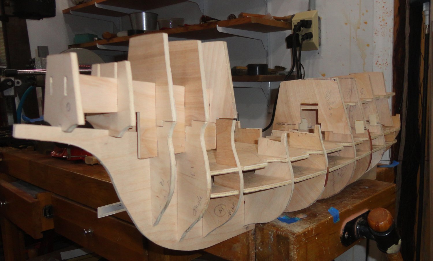
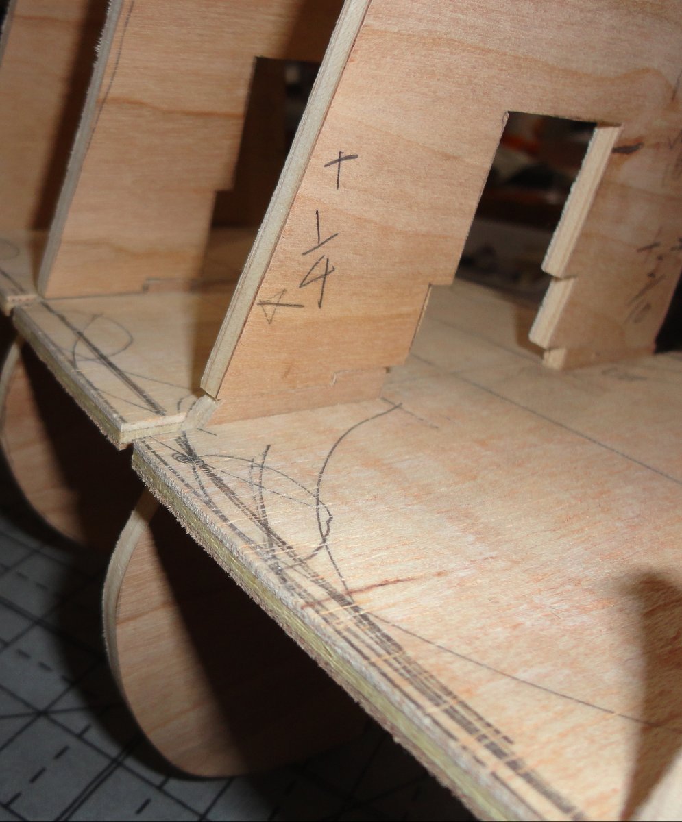
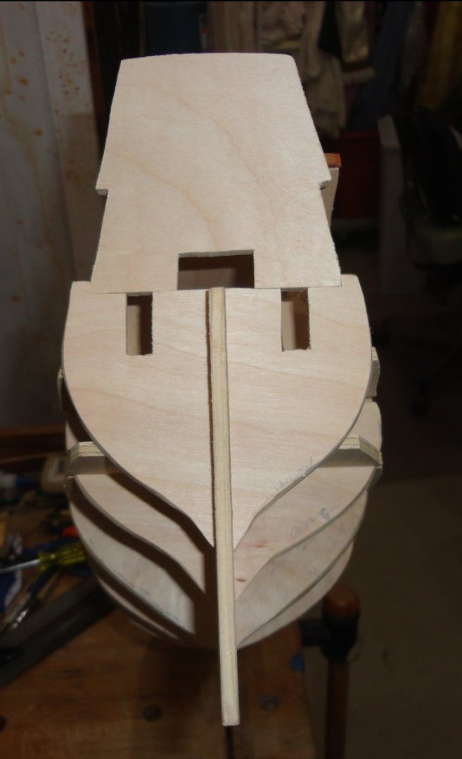
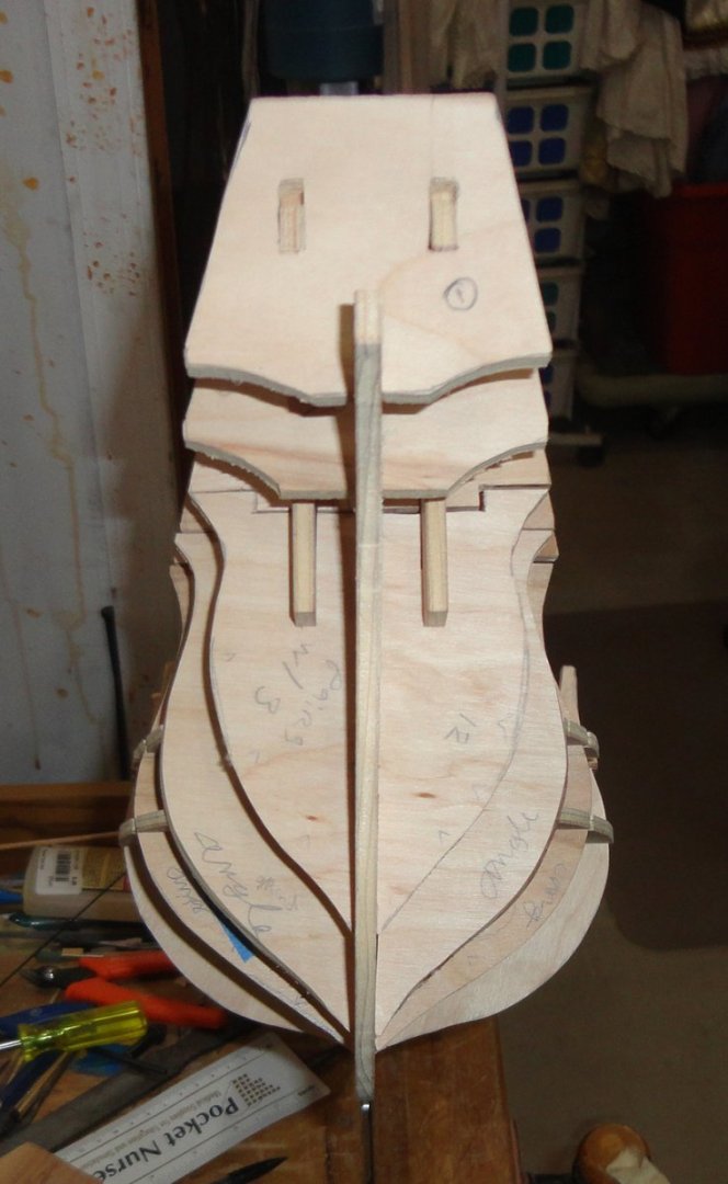
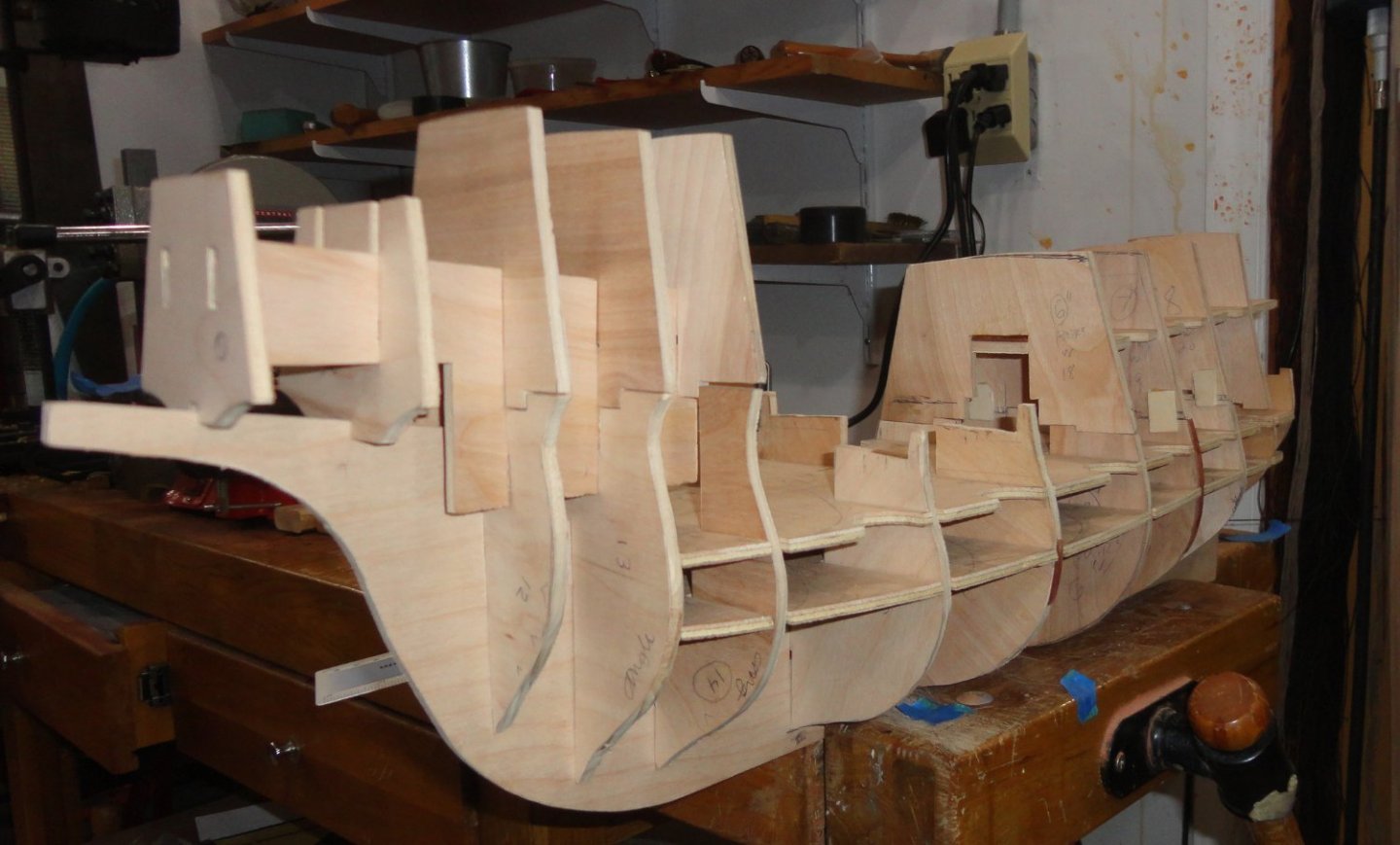
A few more tentative steps have been taken. The techniques I used to draw and reproduce frames, etc. in wood are sub-par to properly generated, symmetrical shapes ... and so there are a number of adjustments to make so the puzzle pieces fit together better (or at all), with tweaks here and there as I go - that then cause other tweaks to be made. One can always cut or abrade off excess material, but even if more wood needs to be 'added' in places - it can be glued on with aliphatic resin glue and then sanded. This is my first go at a self-generated hull form, and it is a fascinating process of discovery ... one that I'm in no rush to do as its a fun thing, and the idea is to savor the experience - for once done I'll have to embark on another voyage. The shot below shows some of the added bits. Fairing is foremost in mind, so a thin spring rod is applied to the hull to see where adjustments are to be made. A number of frames were entirely recut where the changes would be too great on an individual piece. Once everything is fitting well, perhaps I should draw around all the pieces over gridded paper as a future reference ... as well as to post those so anyone else who wants to have a go at the Great Henry can do so. With a plausible framework to begin with, all the rest is done using construction techniques found in many places on the forum. I find the current build-in-progress of the Mary Rose to be educational, but a model of the GH has more leeway since the original ship has been lost to the ages. Blocking between the hull frames seems a good idea. One can use planking material from a 'parts kit' (or cut one's own), as well as scrounged or improvised fittings. One can buy or make guns (the Sergal kit has very many that are perfectly suited) - most of those on the GH will only be seen as barrels protruding through gun ports anyway. I won't use any belaying pins (the experts say 1536 is way too early for them), so tying rigging to heavy railing seems logical, as well as using knight heads with a rail between, and kevels were convenient. I just received the small gun port hinge kits from Chuck at Syren, and they are very adaptable (no 'blackening' needed). Masts and sparring would be typical as seen in depictions available on line. As said elsewhere, the rope in the Sergal kit is excellent, and I can always make whatever rope in the color and size I want with the Rope Rocket (another Syren product). Below is a view from astern showing the lining-up of the aft frames. Compare with an opposite view of the forward bulkheads. I rather think the lines are shaping up, similar to those found on the Mary Rose ... these warships were on the 'cutting edge' of Naval technology at the time of construction. Below is a view from the front quarter ... things are still in a state of flux, and nothing is glued - so pop-ups or loose joints occur. There is also a camera effect that diminishes the apparent size of the stern castle in the photo (which a side view would not have), but I'm happy with how the shape of the fore castle is coming along ... it will remind one of the Anthony Roll. Although the artist perhaps over-emphasized the exact proportions, it shape certainly DID make an impression (as did the fore castle of the MR) on the casual observer. This 'mind's eye' view might be compared to people in the movie 'Close Encounters of the Third Kind' trying to make drawings or sculptures of the mental imagery os Devil's Tower, Wyoming ... without the edifice present for comparison. I'm holding the keel in a wood bench vise, so I'll have to make a better way (building jig? ... cradle?) before long. Both castles will be made as removable sub-assemblies so I can invert the hull form to plank from the keel (doubler plank method). Once the bottom is done, the hull can be turned right-side up for the rest of construction - again working slowly upwards (like I did with the Vasa). I'm making up my own instructions as I go, so we'll see. The last image in this post is a piece I made that the weather deck (of thinner ply) will go on ... and it seems to match (roughly) where a deck is inside the stern castle. A bit of adjusting yet, but so far, so good. Planking will run inside both castles in the central area, but the plan is to have double doors closed (a measure that can secure the castles in action), since I don't want to do 'interior detailing'. I've seen some builds of other ships where the builder goes to considerable trouble detailing and outfitting cabins that will only be vaguely (if at all) seen from the outside on the finished model. Once the entire framework is in order, I'll have to go back and do more work on the Vasa.

- 45 replies
-
- 10
-

-

-
- Great Henry
- Henry Grace a Dieu
- (and 1 more)
-
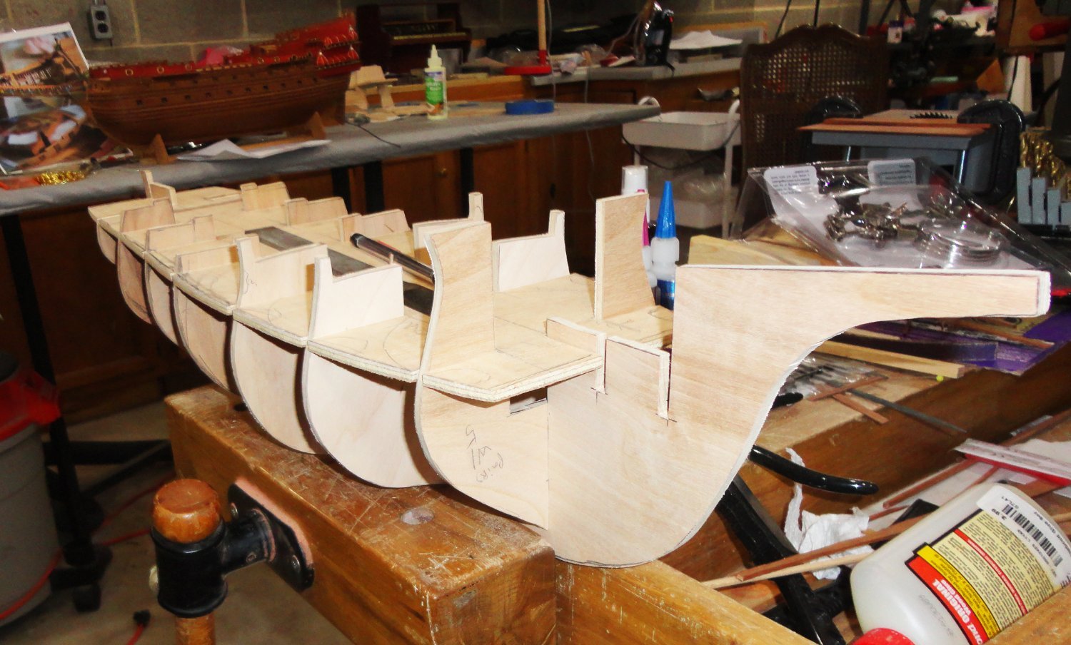
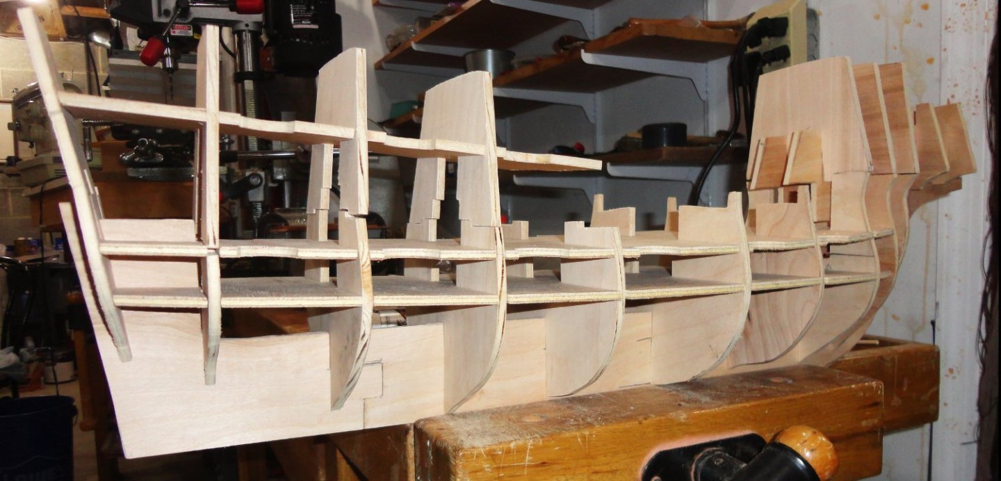
This post should bring the documentation up to date. An initial fitting showed where some of the frames fell short of fair - ergo new ones had to be made ... and trimming done on others. After more 'adjustments', a more complete frame was trial fitted, and things are improving. You can see how the fore castle will resemble the one seen in the Anthony Roll, and the stern castle is the cut-down version of 1536. I did a drawing of how it would look with yet another deck on the stern castle, and the reported 'heeling' was then understandable. Sergal's version has a 'diminutive' deck added (a sort-of 'widow's walk') that does look imaginative, but not anything with documentable.


- 45 replies
-
- 11
-
-
-
- Great Henry
- Henry Grace a Dieu
- (and 1 more)
-
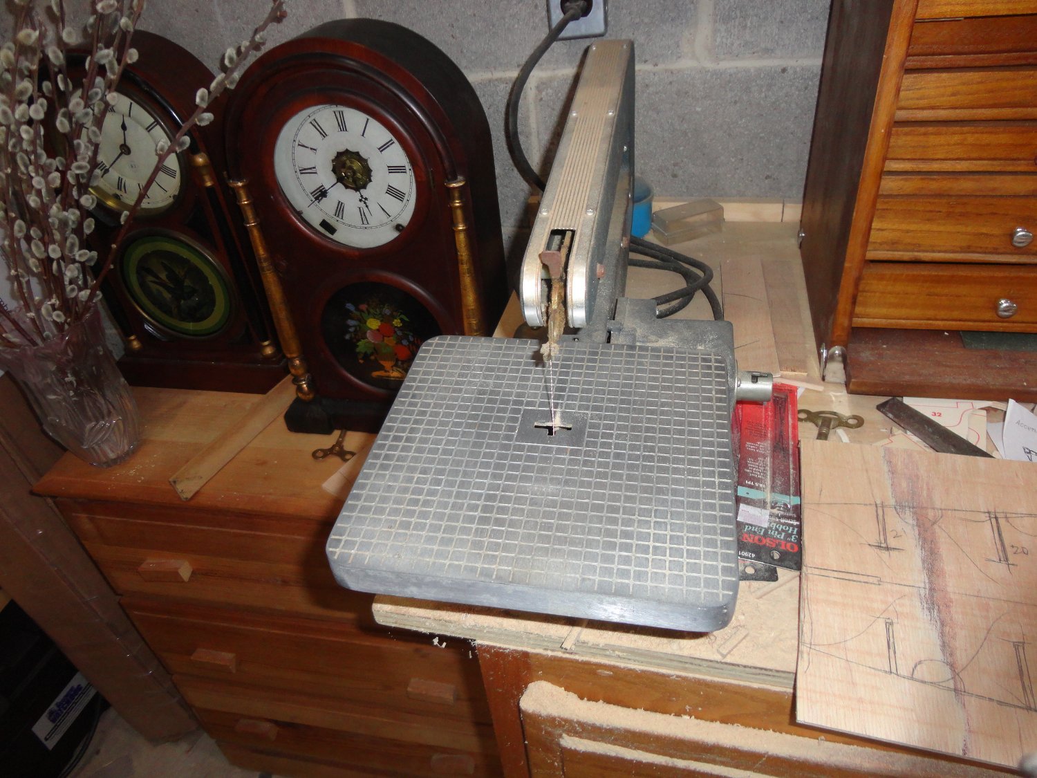
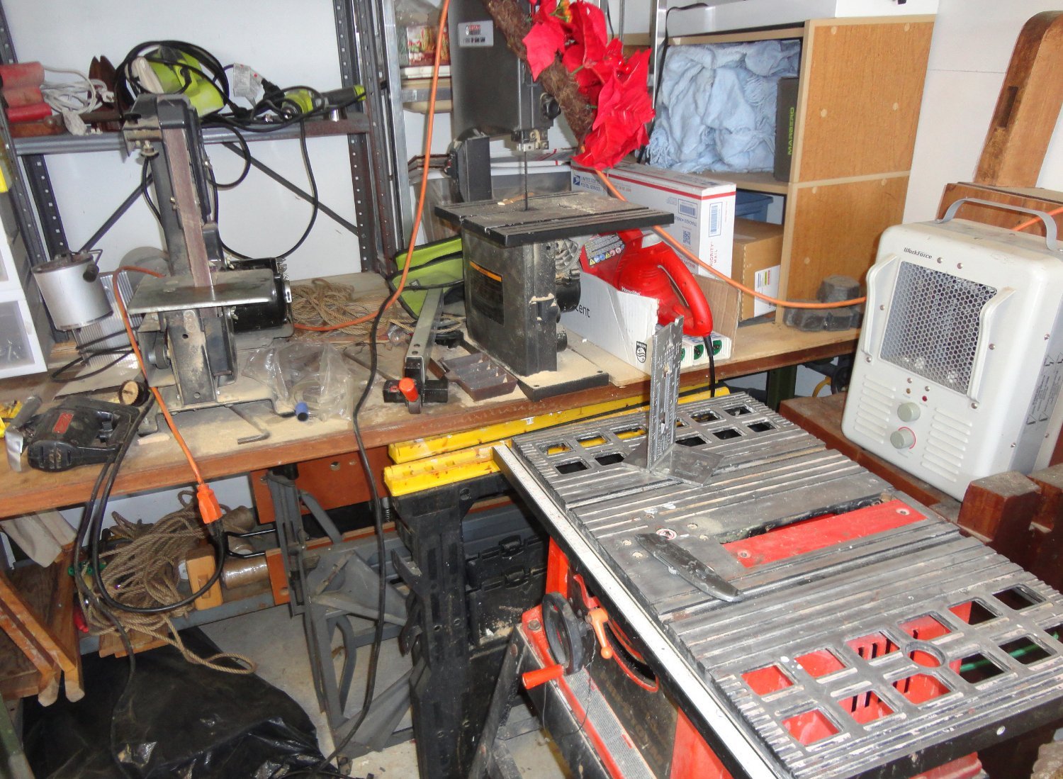
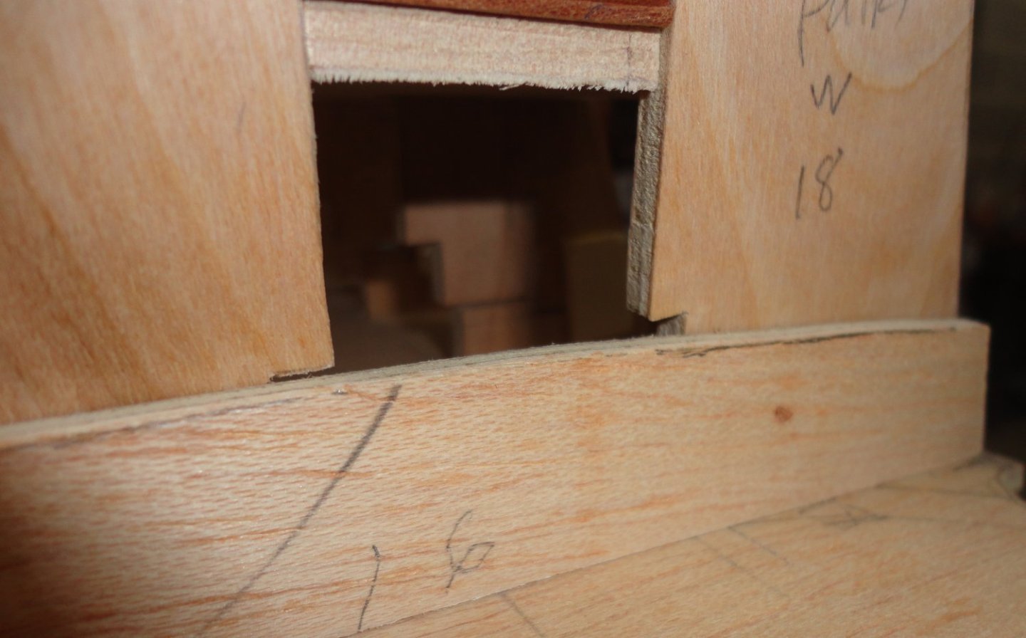
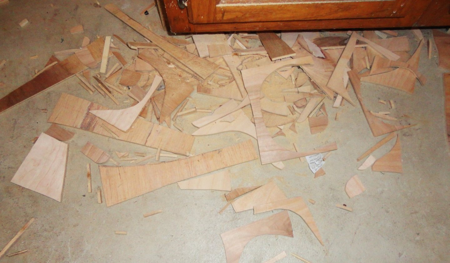
The gun decks had to be re-designed as single pieces, with the width adapted to the new form dimensions. This was done by tracing around the frames at the right location. The notches in the frame members were also modified so the gun decks will have the right fore-and-aft curve. The gun deck above the lowest one will have scalloped notches cut to make it easier to position and glue the dummy gun carriages as the planking progresses upward. Below is a corner where my trusty old Dremel jigsaw is. The newer cheapies aren't well made, but this vintage one is half-decent. BTW, the clock on the right is working, but the other one is not presently wound since it needs some maintenance - a little cleaning and lube should work. Below the jig saw is a pile of scrap I need to clean up before I start tripping over it. As long as I'm on the topic of my 'shop' (such that it is), there is a picture of a corner in the garage upstairs where I can make more dust (so the Admiral doesn't complain about it). It is cold in winter, ergo the heater. In clement weather I'll roll the table saw outside for any bulk cutting, and the sawdust can bury itself into the grass.


- 45 replies
-
- 5
-
-
- Great Henry
- Henry Grace a Dieu
- (and 1 more)
-
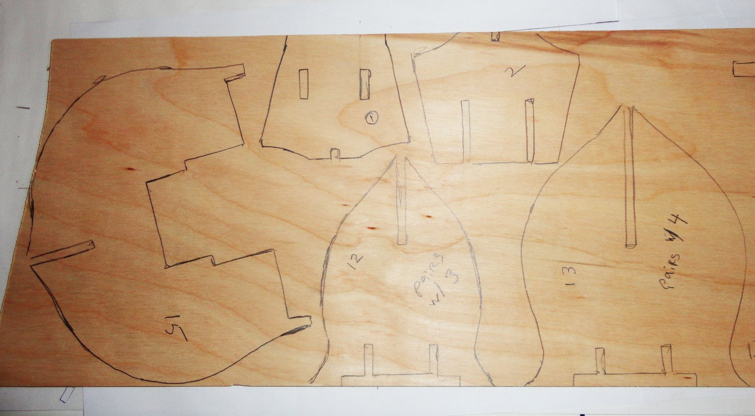
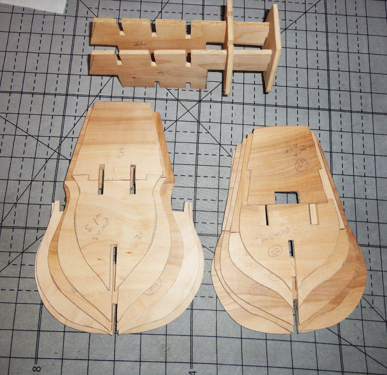
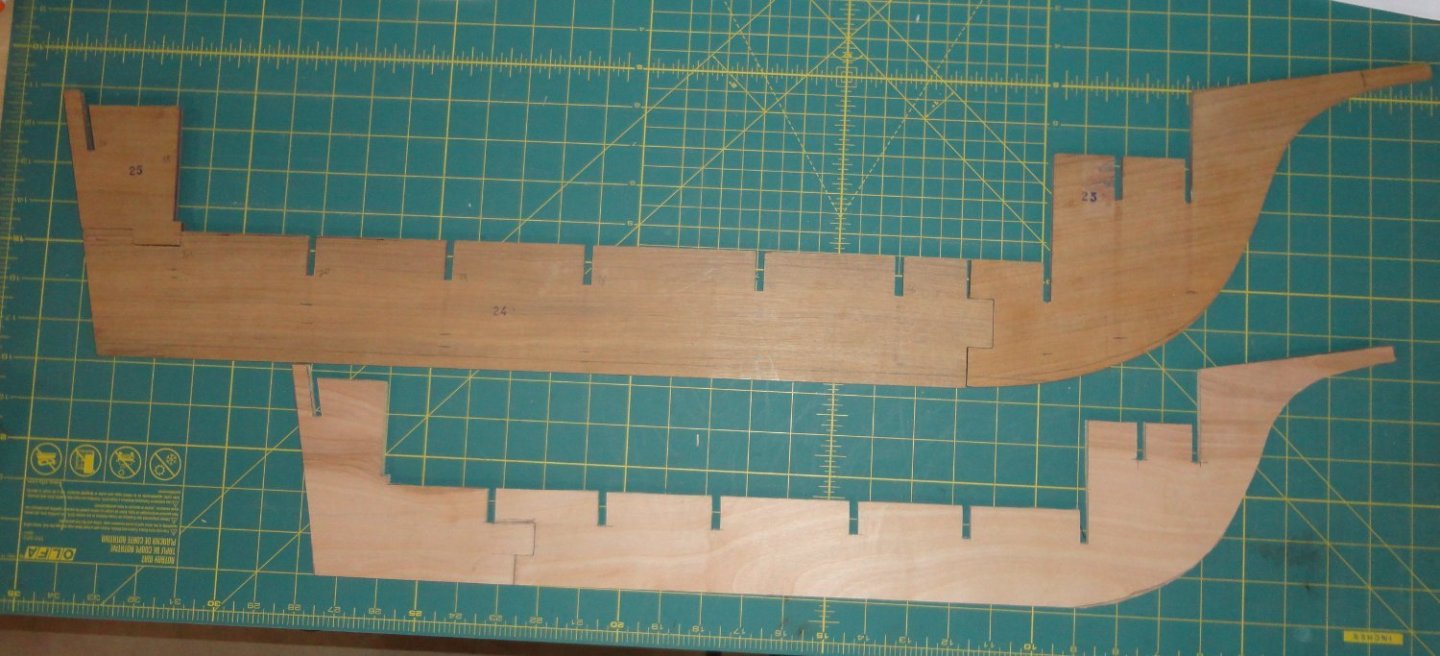
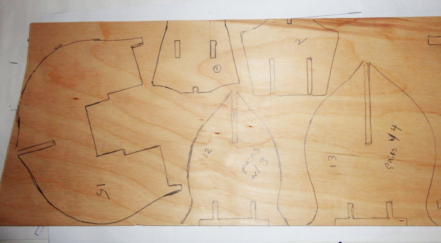
The new keel pieces are placed for comparison with the original pieces, and you can see the degree of down-sizing accomplished. There are no changes to the configuration of this single frame element except the lessen the amount of keel that will project below the nethermost planking, whereas there are very significant re-designs to the cross-wise frame members and decking (which will be seen later). Ideally, I'd use computer aided frame development to get perfectly symmetrical print-outs at the desired scale for gluing to the wood before jig-sawing. What I did was to fold the paper over and cut around the first half to get something close to symmetrical - then trace around it on the wood. I got a piece of birch plywood about .200" thick (2' x 4') and pretty rigid in both axis. I had to look through almost every piece to find one that was flat - and it stayed flat in my shop. I picked another piece at another big-box store to make the gun decks from, since they will have to flex to the shape needed fore and aft. So the piece of stock was chosen from one that was rigid in one axis but flexible in the other. Below id a folded-over paper frame member. My 'hammer and chisel' methods aren't so elegant, and the pieces have to be test-fitted and trimmed as needed as I go. But its 'good enough'. Below are some pieces drawn on the wood. Now after cutting the initial ones out, they don't look too bad. But there will undoubtedly be a few re-makes when I see how the lines look. All this is a 'first ever' for me, and it is a process of discovery.

- 45 replies
-
- 4
-
-
- Great Henry
- Henry Grace a Dieu
- (and 1 more)
-
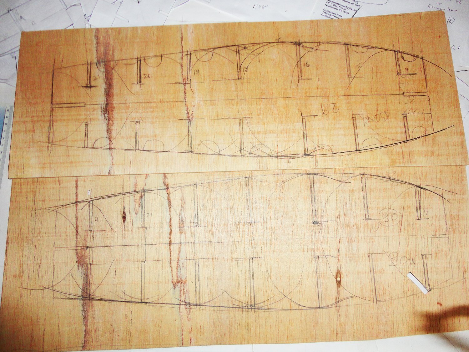
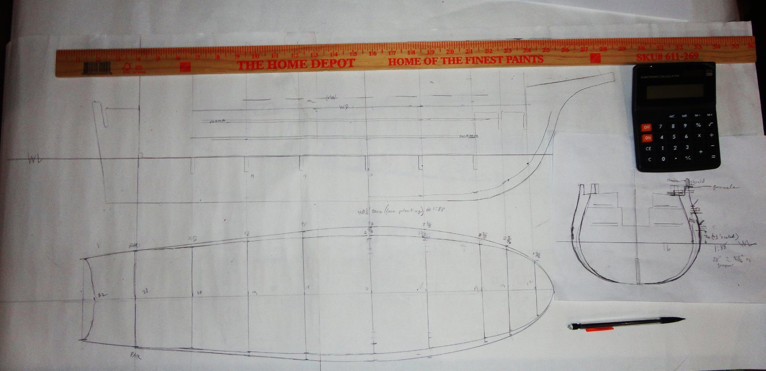
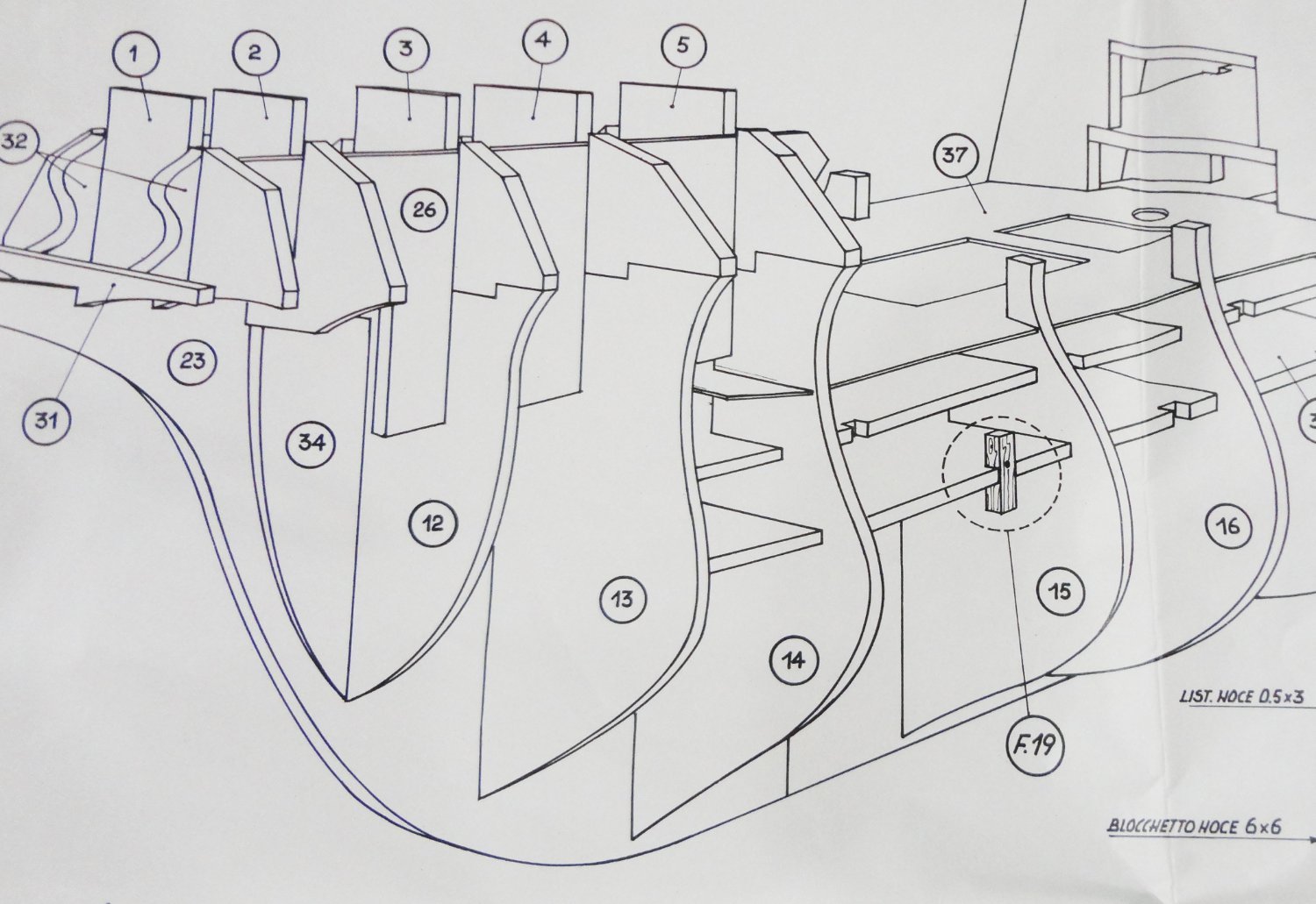
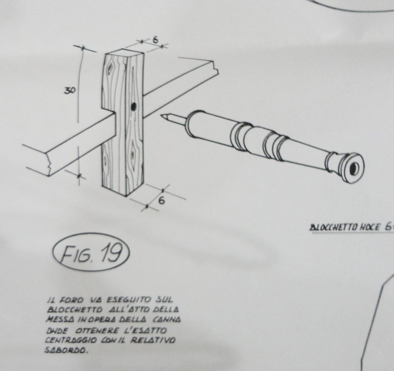
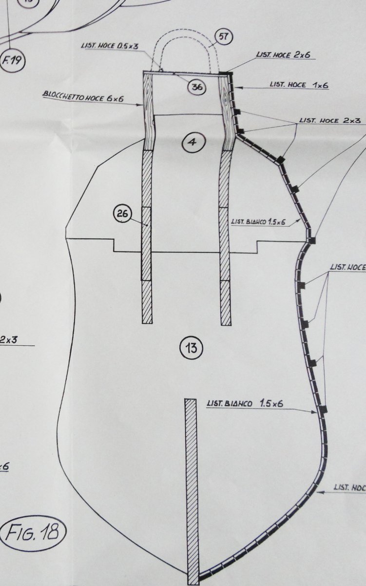
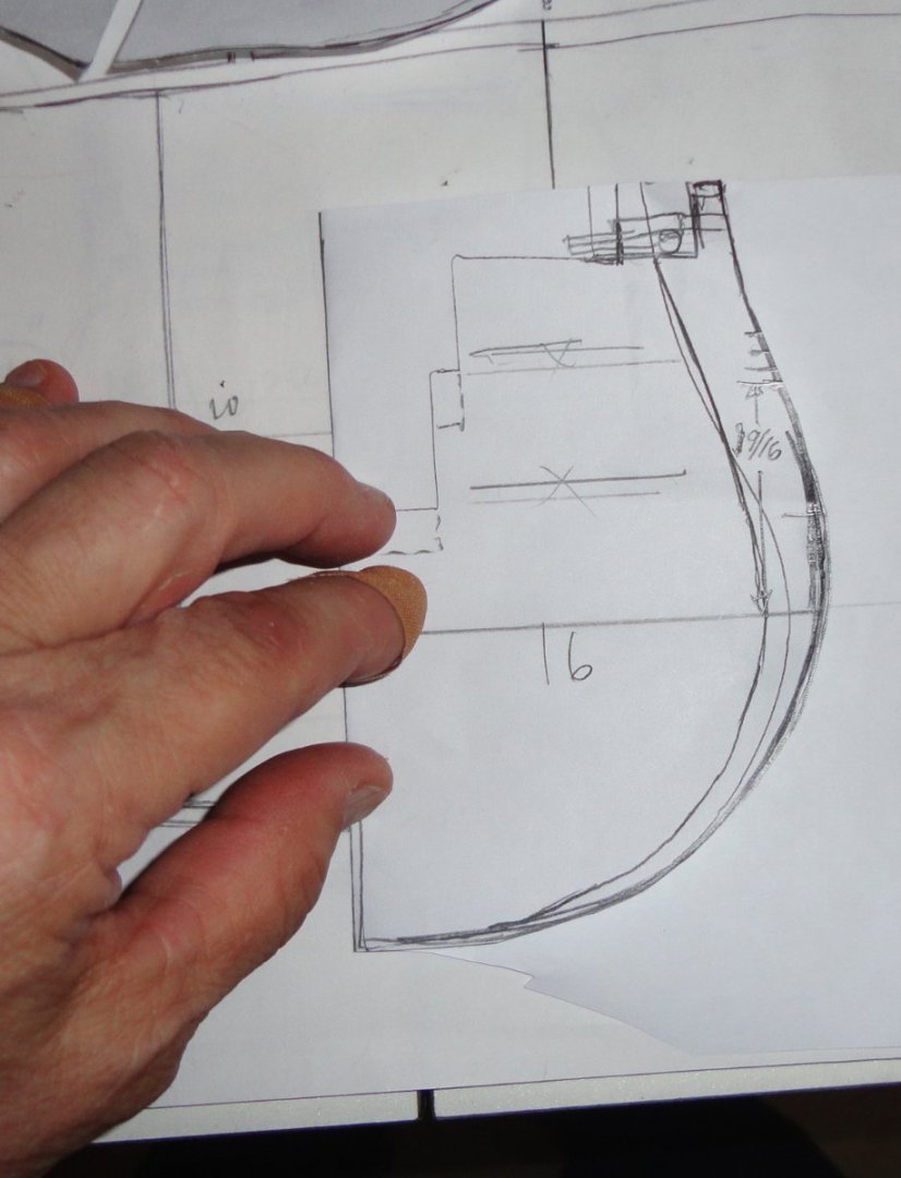
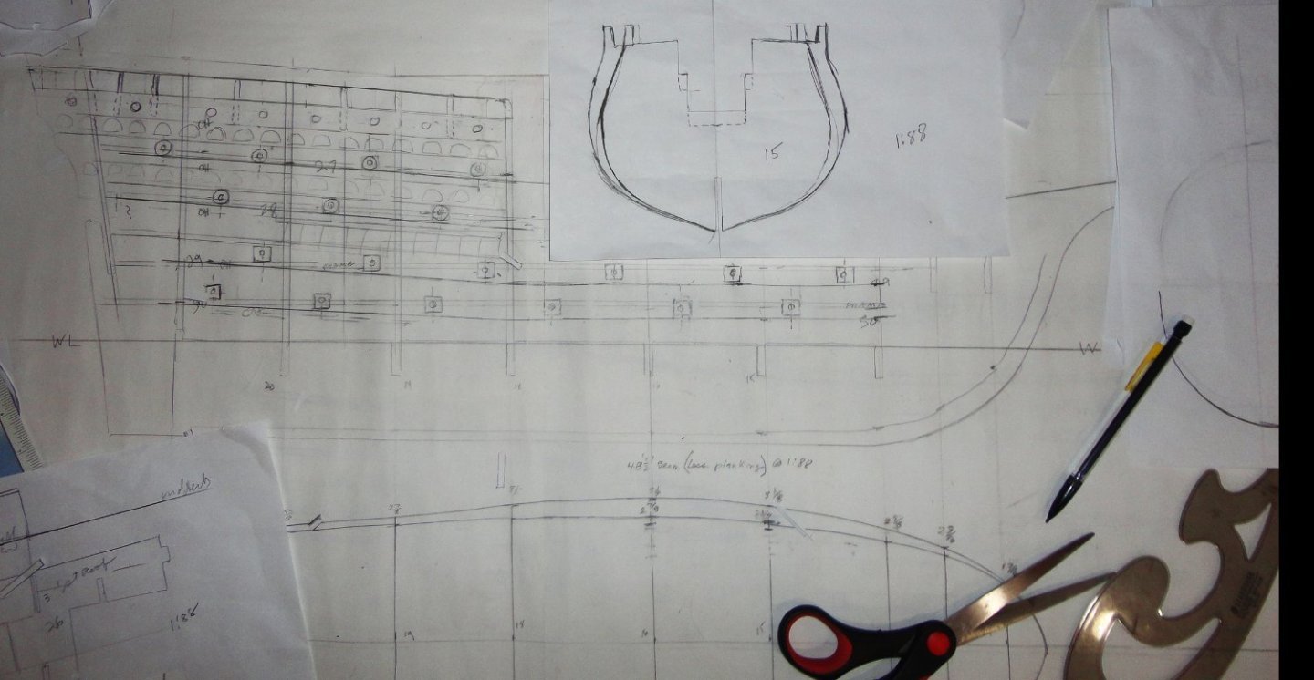
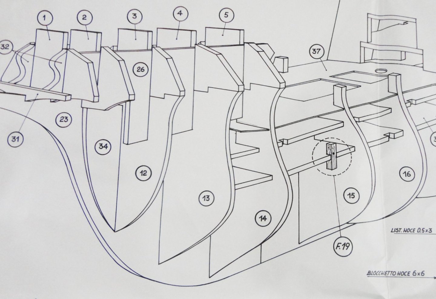
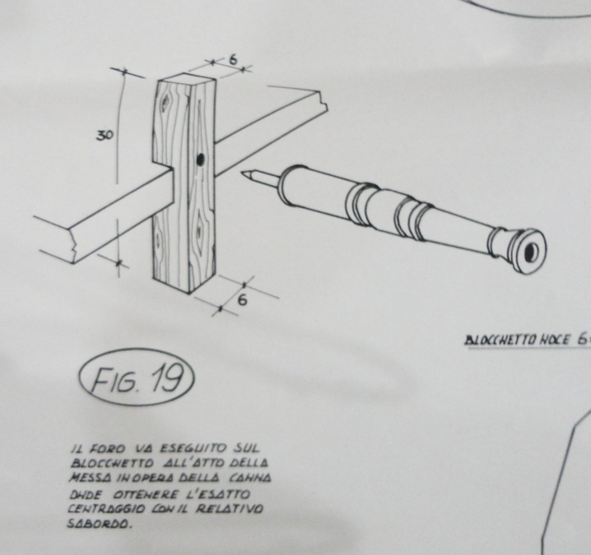
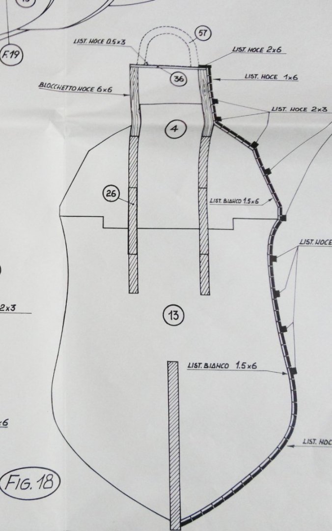
Now its time to hit the drawing board and re-scale the model. The designers 'gallionized' her over much (as there was much less to go on back then), and the beam to length also needed re-doing (as noted in the kit review). I did a fair amount of design work as a junior engineer decades ago - long before auto-cad and cad/cam technology. A proper drawing board with a manual drafting machine would come in handy, but I have to plug away with straightedge, pencil and whatever shapes are handy. The kit frames were placed on my copier and the % reduction was played around with until arriving at my best reckoning of 1:88 - what appears to be the scale of the cannons provided. I also had to adjust the beam proportions and the outer shaping of the frames. Now there is an interesting way that 'false decks' are incorporated in the kit design - but not at the levels where cannon carriages would set on them ... rather the 'approximate' center line of the barrels where the gun ports are to be cut into the hull planking. Wood is intended to be glued into notches at these point, then later drilled into from the outside after planking and cutting the gun ports. If everything does not line up quite right, there will be difficulties with this. Also, just drilling the holes all in alignment from the outside into wood pieces located somewhat behind the hull planking is problematical. My solution was to design complete gun decks (instead of two halves) that will be at the proper level to have either gun carriages (or dummy carriages) placed ... or simply wood blocks that the half cannons can be temporarily put into and adjusted to 'look right' coming out of the gun ports AS the planking proceeds up the hull. We'll let this idea evolve as the build progresses. Below is a rough sketch showing where the original internal decking related to the array of gun ports. The next two photos show the kit concept of how half-cannons would be incorporated - so you can see the challenges noted above. Below is a detail showing an oddly-shaped fore castle ... not like the Anthony Roll at all - go figure. i still haven't translated any of the Italian, but one can see that the hull is to be double planked.

- 45 replies
-
- 6
-
-
-
- Great Henry
- Henry Grace a Dieu
- (and 1 more)
-
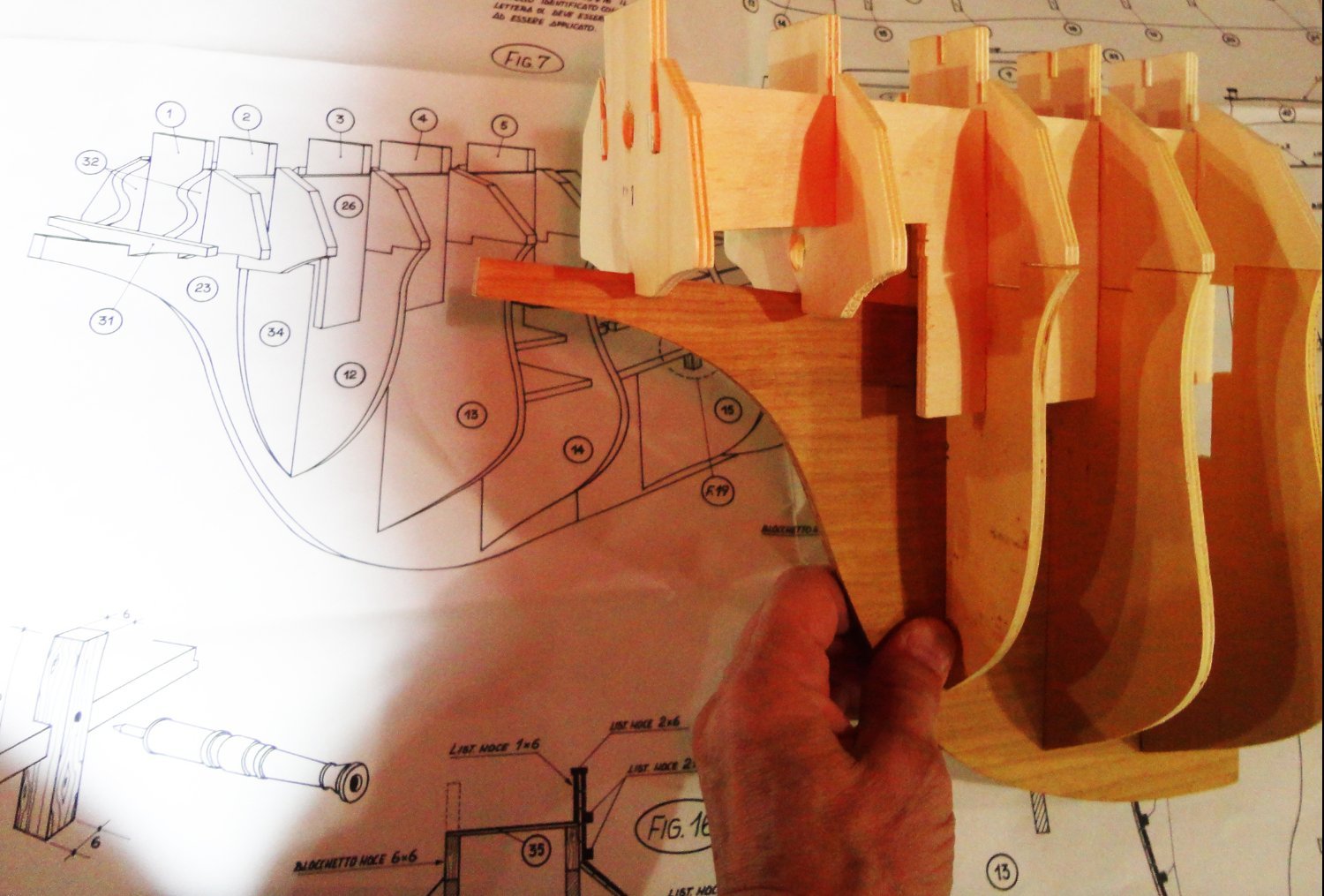
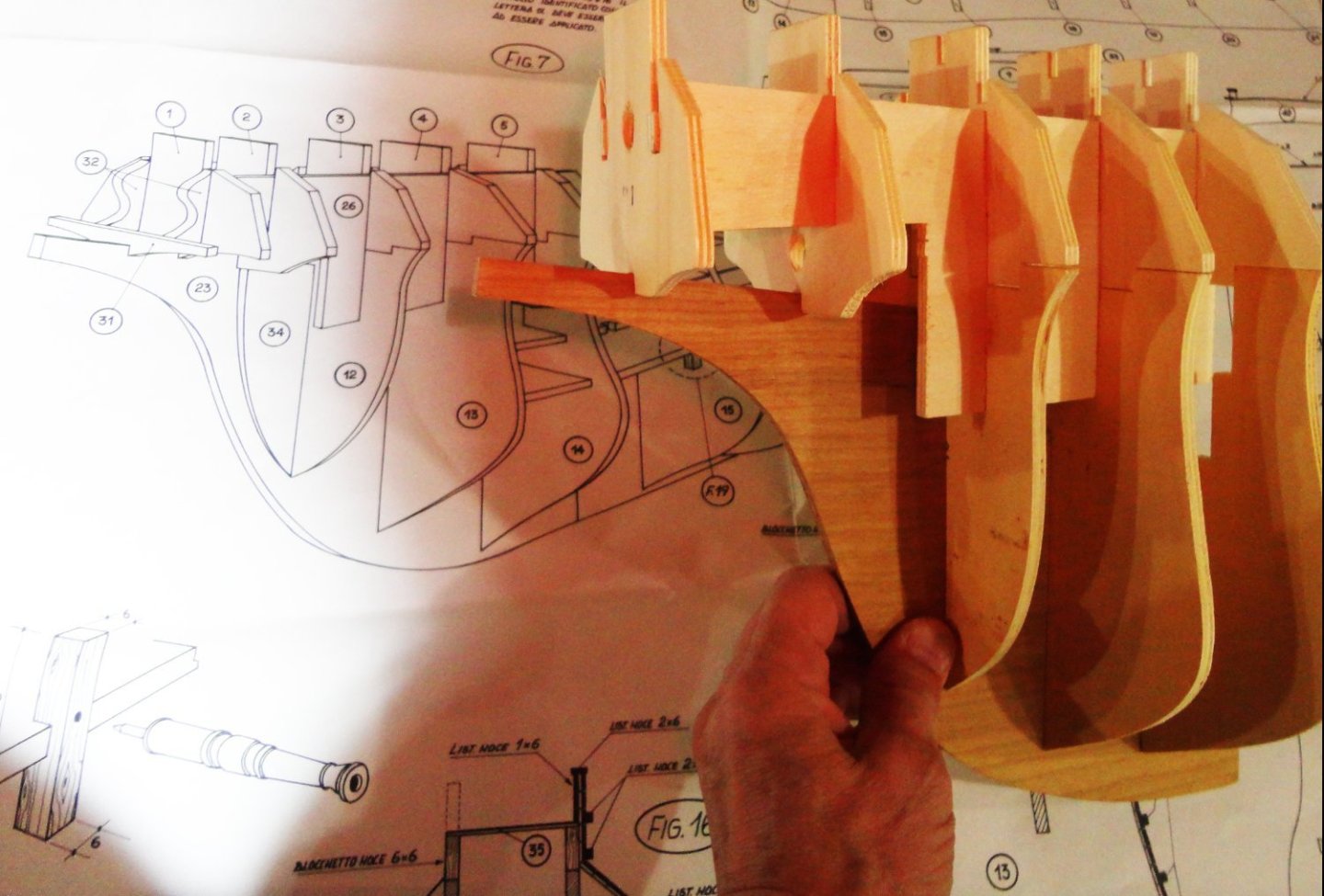
Ahoy, lovers of 16th to early 17th c. ships ! My review of the massive vintage Sergal kit designed in 1975 can be found elsewhere in the forum, and I won't re-hash much if anything covered there (in the review section) ... in fact, the kit review nearly 'morphed' into a build log (never my intent) - so I was bound to eventually do a build after finishing the Vasa log - or so I thought. So in taking a break form the Swedish ship, I started accumulating pictures of a re-design of the Great Henry's framing ... and as the photos mounted I realized that a 'backlog' was accumulating, and would make for a lot of work sorting and getting any future log started. Well, we're used to many logs taking years to complete, and I'll most likely hop back and forth between the two and add occasional additions to both logs as stuff gets done. The full name of this ship is Henry Grace a Deiu (HGaD), and there is a great build of her at 1:200 already completed in the forum. It was a larger and more heavily armed version of the Mary Rose (MR), built in response to the Scottish leviathan Great Michael. There are several reference books on these ships, so I won't go into that here. Having a substantial section of the Mary Rose recovered and on display in England provides a wealth of information not just on the hull lines and construction methods, but this information can be used for the Great Henry (or Great Harry - GH either way) - as well as to correct what are perceived today as inaccuracies with the vintage Sergal kit. 'Hard to figure the thinking in marketing a limited release of a premium, large-scale kit back then, - and they might have done better with with a more manageable version, as the development and tooling could have been amortized over a higher production volume (ergo lowering the price point). The Anthony Roll was known back then, so the somewhat fanciful configuration of the fore and stern castles is amusing. The kit, as issued, is high quality and the framing parts fit well with a minimum of fussing. But we'll see what i have to do to get a more modest sized model conforming much better to what is now known from the MR. Below is a portion of the kit framing to give you an idea of the size.
- 45 replies
-
- 4
-
-
- Great Henry
- Henry Grace a Dieu
- (and 1 more)
-
'Looking good ... Have you thought about the detail seen on the original just below the gunwale (inboard), where there is wood installed with oval spaces between where white shows through?
- 89 replies
-
- 3
-
-

-
- Cutty Sark
- Revell
- (and 2 more)
-
Any day you can 'move the ball a few more yards downfield' is an accomplishment. 'Your hull looks well build to date. Now, if only Sergal would make a 'decent' Thermopylae at the same scale. Their 1:124 is a real challenge, and the reason they went with the smaller scale was to have a low price-point. A better version in a larger scale (it wouldn't take too much to modify their Cutty, since many components are interchangeable) would be a better value even at a higher price.
-
Ahoy Steven ! I've noted the Mary Rose deadeyes with seven (count 'em) lacing (reeving?) holes. And, yes, I'll have to fashion mine to be like those - which will be easier at 1:88 than at 1:200 for sure. I happen to have some 'teardrop' shaped metal lower deadeye surrounds from a parts kit that are about the right size (slightly larger at 1:72, so the deadeyes will be made to fit). My 'take' on this type of deadeye is this (in theory): once laced, the combined mechanical advantage will be much more than that obtained by merely three holes - especially if there are TWO loose ends of line, that is, the lacing does not begin with a stop knot. That way, two men would be pulling on the ends to tighten the shroud above. Once snug, each man would wrap his line end a few times around the lacings near a narrow end of one deadeye (frapping is the term Boy Scouts use when doing ordinary lashing ... wrap twice, frap thrice) and pass the end of the line around the frapping and out to secure with a couple half hitches ... whatever. This would give the arrangement a distinctive look - one different than the later-developed method of having only three holes and a single loose end of line that is tightened by blocks and tackle from above (to provide sufficient mechanical advantage), the free end is threaded up where the shroud is stropped to a round upper deadeye making a little gap there, then lashed with thin line to the shroud in a couple places, the way done with most models seen on the MSW forum. There's plenty of time to work out the details, and I'm now planning to do a post-1536 version. The very large scale of the 'as provided' materials had me thinking that shorter masting (sans top gallants of a pre-1536 version) might help - but not that much. A draft with a taller stern castle did make the vessel look a bit 'krank', which it nearly was according to available sources. Observers 'expect' to see a version resembling the Anthony roll - and most of the artists conceptions one can find on the web, as well as other models made.
-
Aye, the Holbein drawing shows a rowdy crew with a wench aboard ... and also shows the characteristic 'teardrop' shaped deadeyes.
-
I've finished furniture made of 'colored' wood (e.g. mahogany or black walnut) by lightly applying 50/50 'boiled' linseed oil/turpentine and allowing it to cure a few days with intermittent burnishing with a soft cloth - then applying shellac to whatever degree desired, whether a single sealcoat or a gradual buildup of layers. The oil treatment will enhance (deepen) the color and the shellac (whether clear or amber) is compatible if applied over the oil once its had a chance to fully absorb and dry into the wood. When furniture is to be painted with oil-based paint, shellac can be used as a 'spit coat' to bond any loose wood fibers and is lightly sanded before applying the paint.
-
Yeah, there are ratlines in abundance on the HGaD ... but since I want to reduce the scale to somewhat to 1:88 (gosh, the 1:65 hull length provided is intimidating), I'll likely opt for the 'sewing' method of ratline installation. This will prevent oversized knots ... and tying them (except perhaps a cow hitch on the ends so there are no 'short stubs' projecting as seen on some models). There are quite a few ratlines also on the Vasa - work on which has been sidelined while I work on an entirely new set of HGaD frame members at the new scale with; a.) much better hull lines based on the Mary Rose b.) curved false gun decks below the weather deck, c.) a corrected fore Castle configuration and d.) corrections to the length versus beam and stern Castle. Once a trial fitting of both frames for comparison has been done, the new set will likely need further tweaking (assuming another re-work is not required) before photography for the proposed log. It seems like I'm developing my own 'kit' based on Sergal's framing concept, then will be using materials from the Sergal kit for the execution. That beats having to cut my own planking and turning brass cannon barrels. I've not attempted to translate the Italian notes on the massive drawings yet (still might, but the draftsman's 'slant' and modified letters might puzzle Google translate). Its more a case of looking at all the sketches and 'figuring it out' ... cut to fit, bend to suit. It brings to mind old man Einar Billing's words: "You are about to begin the exciting task of building a model ... (which) is intended to be BUILT, and not merely assembled. In consequence, you must not expect the parts to fit perfectly, (and) it will be necessary to exercise skill and imagination in the building of this kit - as thought and care should be exercised during construction. After all, any child can put a puzzle together." So the venture will be something between a major 'kit bust' and 'semi-scratch'. Once phase one (frame definitization) is accomplished and documented, I'll have to go back to the Vasa since there are some similarities in masting and rigging - a good dry run to be sure. And I may flip back and forth between these two ships ... and all the other services rendered for the Admiral.
-
Thank you for sharing. Your work is both sensational and inspirational !
- 56 replies
-
- 4
-
-
-
- Sea of Galilee Boat
- SE Miller
- (and 1 more)
-
'Figured it was likely a 'temporary' glitch ... and reminds one how quickly things could just 'go away' in the event of some cyber-war, gigantic solar mass ejection event aimed directly at earth (one knocked out all telegraphs in the 1800s) or some global catastrophe (don't want to imaging one right now) . The convenience and scope of information available at one's fingertips through this and other forums is awesome, though, and it sure beats the 'old days' of scrounging through municipal libraries - which never had the sort of 'builders' techniques' laid-out with such clarity. I'm doing things I never thought practical (or even possible) with present technology ... from complex spreadsheets to Photoshop wizardry to sound editing and desktop publishing. 'Guess the rewards justify the risks, and one can always try to minimize those with multiple thumb drive AND paper backups.
- 24 replies
-
- 12
-
-
Next NRG Conference
Snug Harbor Johnny replied to YankeeClipper's topic in NAUTICAL RESEARCH GUILD - News & Information
Yeah, 'guess the major East Coast maritime museums have all been previous sites for the NRG ... and I'm a recent new member. So what about ... The Erie Maritime museum and U.S. Brig Niagara in Eire, PA The Maritime Museum of Sandusky, OH - just west of Cleveland The U.S.S. Cairo Museum in Vicksburg, MS -
Next NRG Conference
Snug Harbor Johnny replied to YankeeClipper's topic in NAUTICAL RESEARCH GUILD - News & Information
Possibles ... The Mariners Museum in Newport News, VA. - many artifacts on display including the Monitor remains, close to Colonial Williamsburg and other historic attractions The Independence Seaport Museum in Philadelphia - exhibits plus the U.S.S. Olympia, close to the Museum of the Revolution & historic sites, travel by Amtrak is possible due to the proximity of Pennsylvania station The Mystic Seaport Museum in Mystic CT Baltimore 'Inner Harbor' area (would need a hotel venue close to the harbor exhibits) -
A very resourceful solution you've employed, and I'm a fan of laminating layers for bent shapes needed - and I'm also a fan of veneers. You could consider applying veneer 'planks' between the stanchions of the bulwarks to simulate planking (rather than just leaving the solid surface of the supplied plywood bulwark provided in the kit). If done before the stanchions are applied, then single, long strips are easier to work with - but one can still add shorter lengths of typical 1/80" veneer between the stanchions. The Endurance was built with multiple layers of planking that added up to a VERY thick hull (something like a couple of feet in places where the ice pressure would be greatest).
-
HMS Victory Renovation - Outer Planking Removed
Snug Harbor Johnny replied to Steve20's topic in Nautical/Naval History
I wonder what the model's sails are made of ... -
Given that Steve lives 'down under' in Australia, how about pineapple upside down cake?
- 740 replies
-
- 6
-

-
-
- Tudor
- restoration
- (and 4 more)
-
HMS Victory Renovation - Outer Planking Removed
Snug Harbor Johnny replied to Steve20's topic in Nautical/Naval History
'Saw this interesting story with a connection to Admiral Nelson ...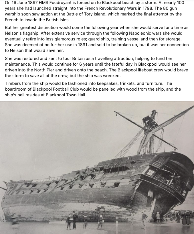
-
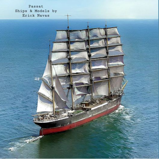
'Saw a nice photo of a clipper under good sailing conditions ... and the sails are angled as they should appear for models under sail, with a breeze coming from the stern quarter. Since she's riding high in the water, there's no cargo.
-
Kudos to you, sir ! You've finished a tour-de-force of a fine smaller scale model of what was a substantial ship. A much larger scale project is more compatible with my skills these days. Thank you for such a detailed log ... a great reference to those who may follow with this ship.
- 740 replies
-
- 7
-
-
- Tudor
- restoration
- (and 4 more)
-
Roger, You're 'right on' about all the expertise on the forum (for those who invest the time to search and learn) ... in my 2 years so far I've learned more about sailing (and also steam) ships than I had up to that time. And every niche has specialists with much to offer. You're also right about the Anthony Roll sketches - and there are still a number of other paintings & other artwork that shed light on these relatively early ships. I say 'relatively', in that the 4,000 + yr old Khufu barge is REALLY early. BTW, I watch builds of ancient galleys (how 'bout that Mycenaean reconstruction) and other boats the the 'Galilee' with great interest. 'Guess I'm not a 'specialist' but one with a love of learning, as all the eras are fascinating to investigate. So now (for the moment) I'm drawn towards Henry VIII's big ship, and once agin, you are spot-on with the advice to look into the lines below the surface of the water. It is very fortunate that we have as much of the Mary Rose as we do, and there are excellent hull lines in the 'Anatomy of the Ship' book on the MR. The Sergal kit (given its 70's antiquity) has inappropriate lines, and I've already started working on frames that will be a lot closer to the ones on the MR. The logic being that the HGaD was built shortly after, but 'manned-up' a good bit, as if the Mary Rose 'grew a set'. The MR represented the cutting edge of warship development when construction began in 1509, and the HGaD likely followed suit. Nice work on the Revenge, Grandpa ... Johnny
-
'Looks like the Science Museum Group model has heavy beams to support the overhang in the prow area of the model - something mot seen in the Anthony image ... but then one does not see a dragon (or monster) figure head mounted on a stempost, as was typical on carracks of that era. Hmmm, I don't imagine that they'd have taken it off in 1536. The Anthony drawing does not show a cutwater either, and I doubt THAT would have been removed. This shows the challenges of trying to interpret 'too much' into any piece of artwork. How lucky are those who have either photographs or recovered hulls to guide them ... noting that the forecastle of the Mary Rose has (to date) not been found (and may never be). I don't think that there were vertical curves on the forecastle, as straight timbers were most likely used to build the 'fort'. Yet the Anthony picture has a curved profile of the back ... and if combined with the reverse curve near the bottom ( IF one posits that there was no cantilever at the gunwale), there would be a 'S' curve to the back profile of the fore castle (unlikely). Once again, there is a lot to think about. I'm in the process of making an entirely new set of framing pieces (what Sergal uses for the kit is actually a nice structural design) in a smaller scale to work with as part of the considerations. Obviously, modifying and otherwise proving-out the frame and concepts BEFORE doing any planking is advisable. And I can cut-to-fit or remake portions as part of the discovery process. This is likely how the build log will have to start.