Snug Harbor Johnny
-
Posts
1,501 -
Joined
-
Last visited
Content Type
Profiles
Forums
Gallery
Events
Everything posted by Snug Harbor Johnny
-
 I'm in full agreement with you, Hamilton. The question to ask oneself is, "Am I having fun?", alternatively, "Is this project sustaining my interest?" I like to use what's handy, or available without spending too much - the reason I bought some scribed basswood decking (for a smaller scale than your project) instead of trying to sweat doing tiny individual planks, although fiddling with infinitesimal details does 'float the boat' for some. 'Standard' quality blocks provided in most kits still can be worked a little by hand to improve their appearance, like enlarging the hole for the line a tad to make threading easier, and rounding the edges/profile a little by hand if they are not too tiny to begin with. 'Love your Bluenose, and only wish I had the one my Dad made ca. 1950 ... I didn't see it among his estate items, so it may have been given by him to someone else along the way.
 -
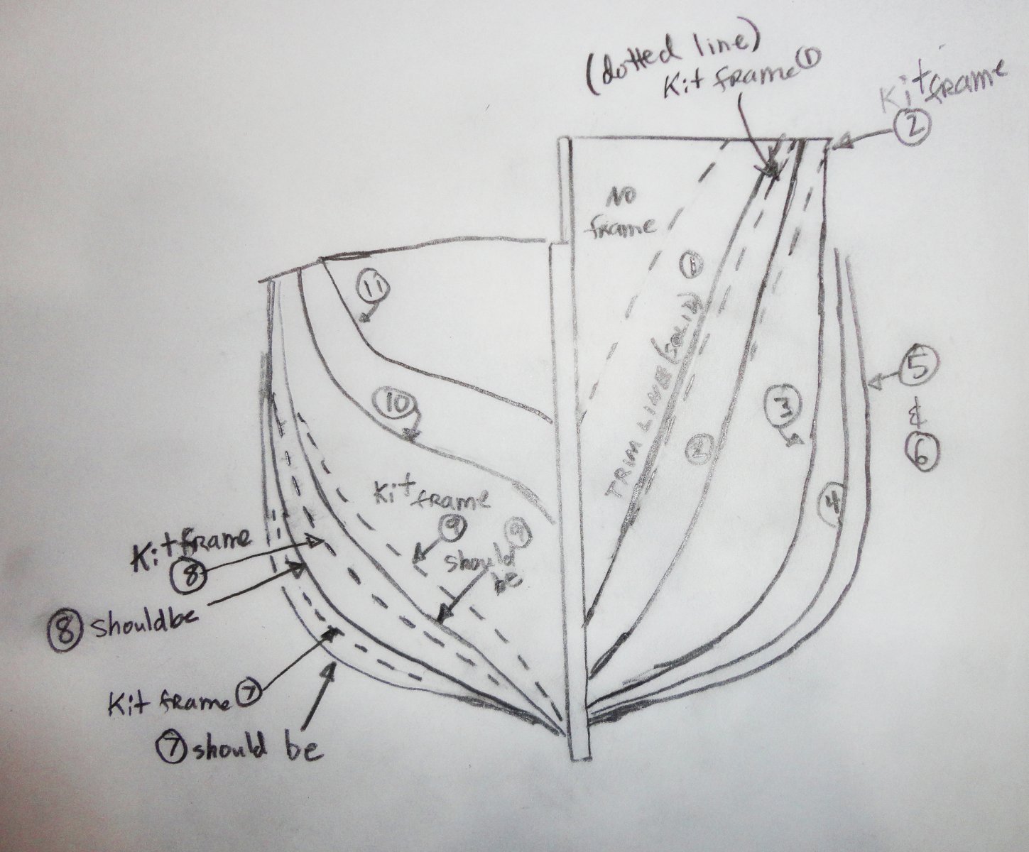
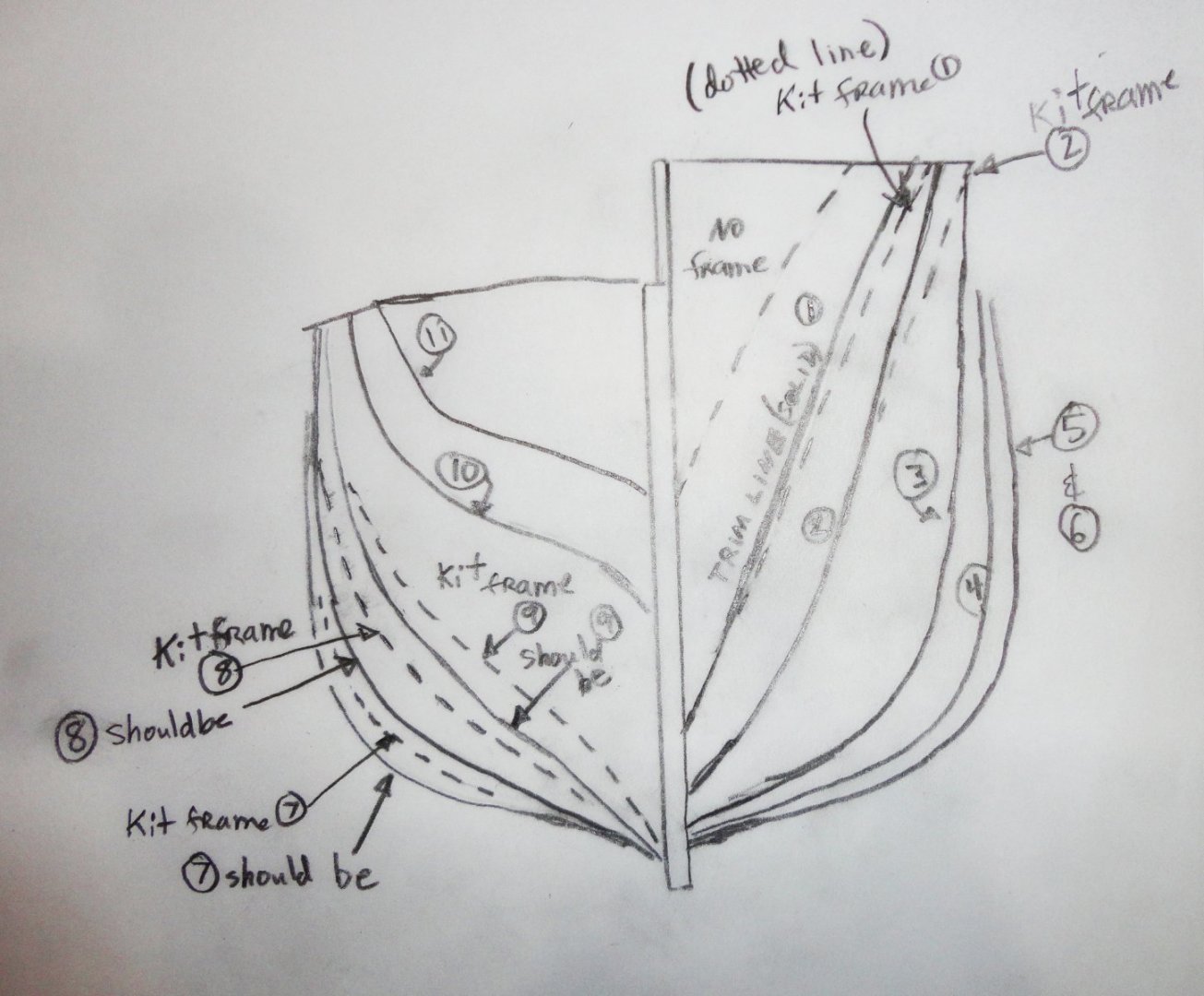
Seeing profiles of the planked hull that you have so far give a nice visualization of the lines - and something subtle I noticed in my kit review of OcCre's Endurance. The bow flare of the kit is a little more than seen in forward photos of the ship, as well as published lines. So I'll trim the first two kit bulkheads a tad to correct when the time comes, and this will impart a little less 'twist' to the solid bulwark piece provided (which can be pre-planked as you've already done. Bulwark installation and subsequent planking will then be a little easier at the bow. Conversely, kit bulkheads 7, 8 and 9 are not as wide as the ship's lines would indicate, and one can see some lack of fullness in this area. New builders can revise these bulkheads (either by bonding additional material or cutting replacements on a jigsaw) prior to framing. Planking then would be less easy towards the stern, but would have correct lines. I suspect the designers opted for ease of planking, and the difference would not be noticed on the finished model. The drawings posted in the kit review can be confusing, because there is no kit frame forward of the first one provided in the kit, so I made another to show the frame differences I'm talking about.
-
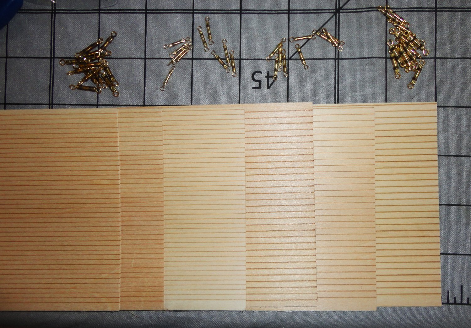
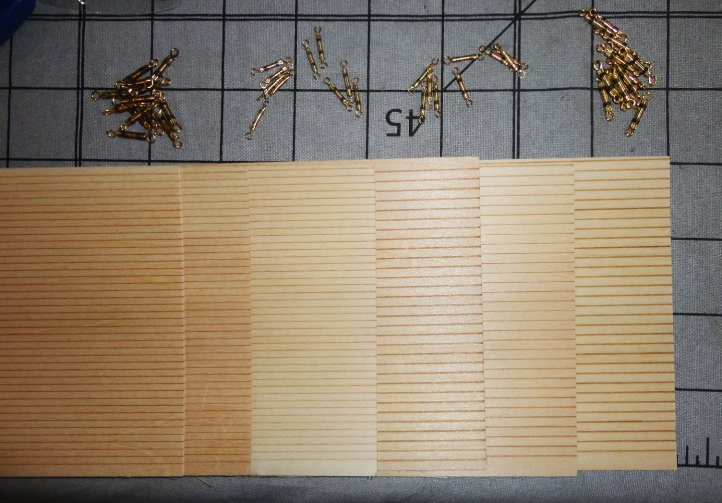
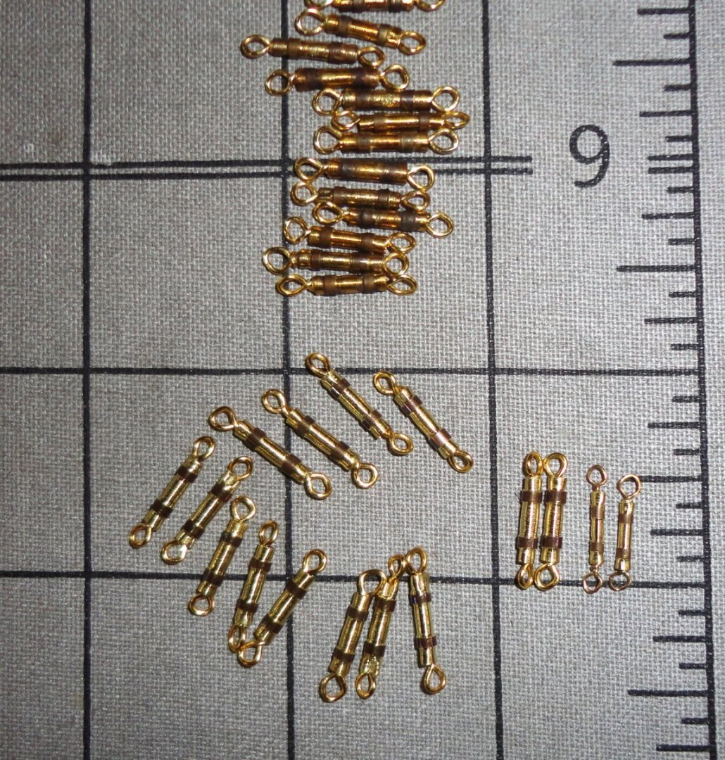
The scribed deck planking came today - 3 sheets each of 1/8 and 3/32 wide scribe lines on 1/32" thick basswood on 4" x 24" sheets - as noted on another MSW thread. I figure the 1/8 wide planks should be about scale for the Endurance (about 1:70 or so) and the 3/32 should be OK for the Great Harry at 1:88 - and is also good at 1:96 - as the 'target width' represented might be 8 - 9 inches. I figure this will be a time saver, and a scoring blade can be fashioned for each size to place separation where individual planks butt. I fancy that a staggered pattern for butted planks is likely the look to go for. Making tiny dots at the butt joints is right out ... 'Guess at any scale there must be some formula to find the 'cutoff' to determine at what point tiny details may be omitted. Maybe it was if the scaled-down size of something is less than 0.010" - don't worry about it. Whatever. A photo below shows the decking, plus 19 of the 26 small turnbuckles needed made so far (I'l do 30 to have spares) - and some of the larger turnbuckles.
-
Back in the day (before power point and other graphic display aids) manual wall charts were done with a product called 'Chartpack', both for grids and also graphing lines. 'Don't know if any of that stuff is around today (probably not, and the sticky side like is gummy), but the top part was made of stretchable plastic that could go around curves, and came in a number of colors.
-
I see in the historic photo the nice, large lubber hole ... AND that there are fairleads very close to it, so the control lines from above will pass down inside the "shed" between the shrouds coming up and the lines angling down from the lower deadeyes at the perimeter of the top. This permits crew unobstructed passage up the ratlines of the shrouds and onto the ratlines of the futtock shrouds.
-
That may depend on how much filler is on the surface, and what type of filler it is. Once upon a time a project of mine had filler all over the surface (it was a large model of a B-29 out of reasonably good solid balsa underneath. There were a couple area where it was thick and the filler flaked off in places and had to be repaired before painting. After painting, the layer of paint may have stabilized things as there were no more flaking. 'Seems that a clear coat sealer might do the same thing. Then the planking (pre-bent where needed) should stick with aliphatic resin (e.g. Titebond), and will also bond along the edges plank-to-plank. Light sanding will remove any unevenness and glue 'squeeze out' that may occur in the process of final planking.
-
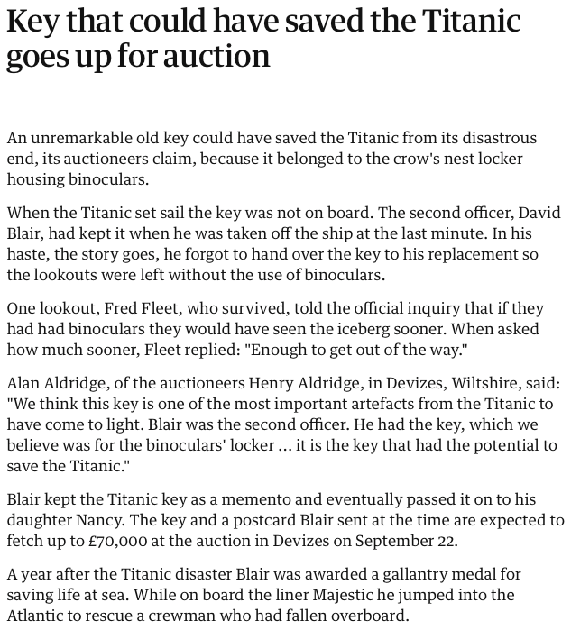
'Just saw this and it gives one pause to think ... what if ? And if I was the officer later assigned to manage the lookouts, I'd have ordered a mechanic to break open the locker to get at the binoculars. Especially if the ship's safety were involved, it would be easier to ask pardon than permission.
-
I've been looking for a source of scored planking for a while ... now I know to look for it at Model Shipways. THANKS !
-
Charles W. Morgan Whaling Bark Kit
Snug Harbor Johnny replied to Frank Burroughs's topic in Plastic model kits
Most definitely - so one does not have to deal with excess flash or more 'rubbery' plastic to boot. -
Super job to date - especially pre-lining the bulwarks with thin planking ... another opportunity seized.
-
I'd put a backing piece of thin wood on the inside (with a little Saran Wrap between it and the planks so there can be no accidental gluing) held in place with a couple clamps ... use two horizontal strips on the outside to prevent the clamps from denting the outside of the planking. Then cut a piece of patching plank from the same wood as the planking ... having a card-stock template (made with trial fittings) can help, then by lightly tracing around the card stock with a mechanical pencil will give you a slightly oversized patch that you can shave where needed. It should be still be sung before gluing. Use blue 'painters tape' to mask around the edges of the planking already in place to prevent glue slops. (That can also be done on the inside before step one as an added precaution.) Sparingly put glue on the edges of the patch and the planks, and that will act as a 'lubricant' to ease the snug patch in place ... use Titebond or equivalent aliphatic resin wood glue. If needed due to the shape of the area, place Saran wrap over the patch before the glue 'grabs', cover with another piece of thin wood, then clamp as needed - the wood 'outer sandwich' inside and out will prevent denting from the clamps. Do not use too much clamping pressure, or excess force can 'telegraph' through the protective wood and affect the planking beneath. Give it a couple hours at least ... half a day is better - what's the rush? Then undo everything, and you should be able to LIGHTLY sand the area with very fine sandpaper and a little closed-cell foam in back of the sandpaper. Everything should blend well enough - of course there will be evidence of a join - but repairs were not uncommon on wooden boats.
-
The print-on-demand Boy's Manual of Seamanship and Gunnery (2nd ed. 1871) finally arrived from India, and it is mostly text - with only a few illustrations ... definitely not the source of rigging detail I'd hoped for, but can be of interest to some. One illustration depicts a temporary repair of a shroud (when shot away), where a pair of small deadeyes 'always kept fitted' have the tail from each spirally wound up then down the parted shroud - which is then tightened with the lacings through the deadeyes. A wide variety of activities are covered including (aside from general seamanship); gunnery exercises, musketry, Snyder rifle drill, Naval cutlass exercise plus rules and regulations. Perhaps good for some reading on a rainy or winter day as a break from doing anything else. Right now, lawn tractor maintenance calls (having run errands for the Admiral earlier). Perhaps this week I'll be allowed to retire to the shipyard some.
-
Adding a design to a sail
Snug Harbor Johnny replied to Seamus107's topic in Masting, rigging and sails
Steven, Your Great Harry (in my opinion) ranks as one of most interesting builds on MSW - a fine job at a difficult scale (although there are some tiny marvels done by those with an 'elite' level of skill I can only dream about). My Henry project is on hold while I learn rigging skills on the Gorch Fock 1 restoration, but I intend to post drawings of the frame pieces on gridded stock for anyone wanting a 'starting point' to do GH. -
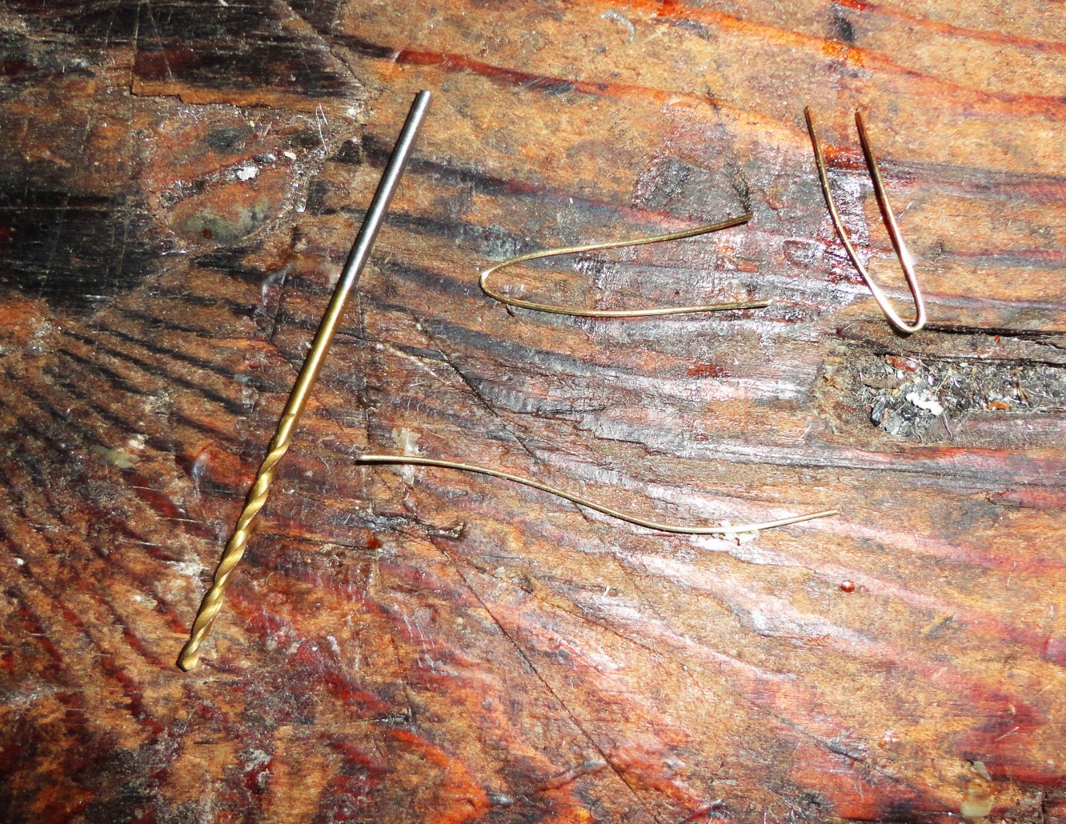
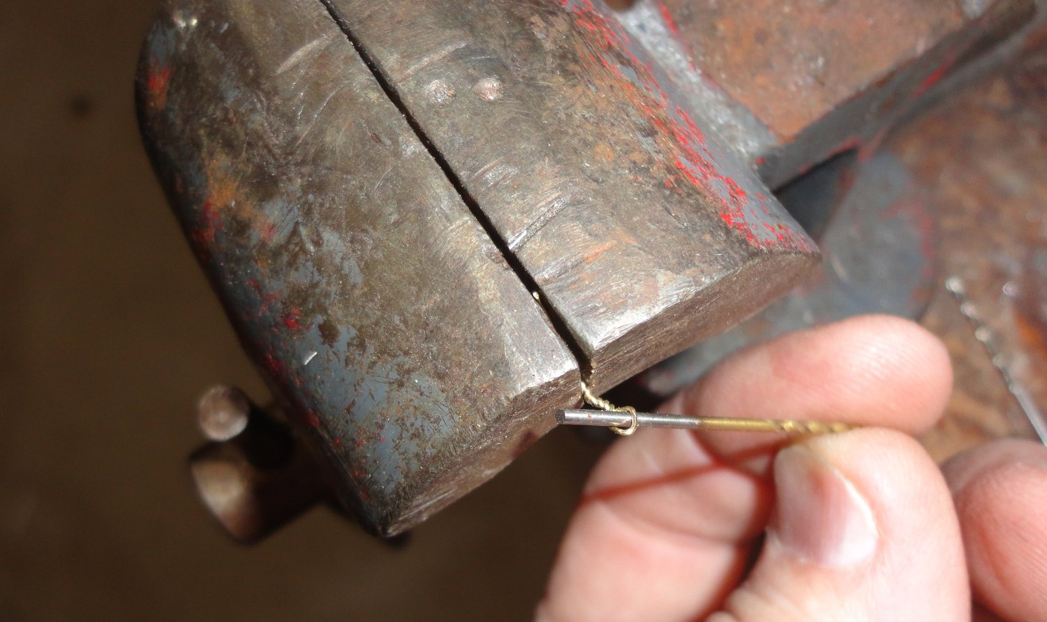
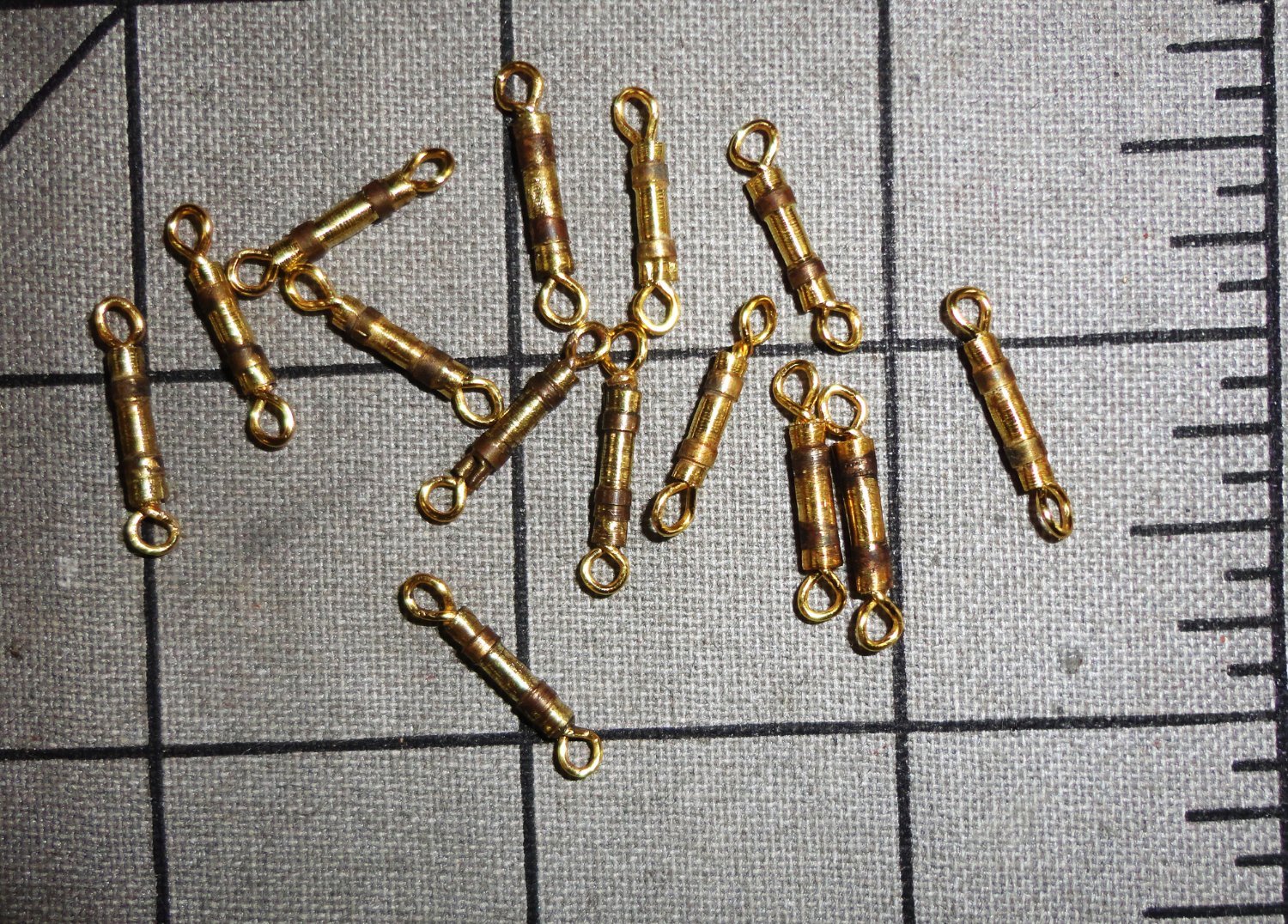
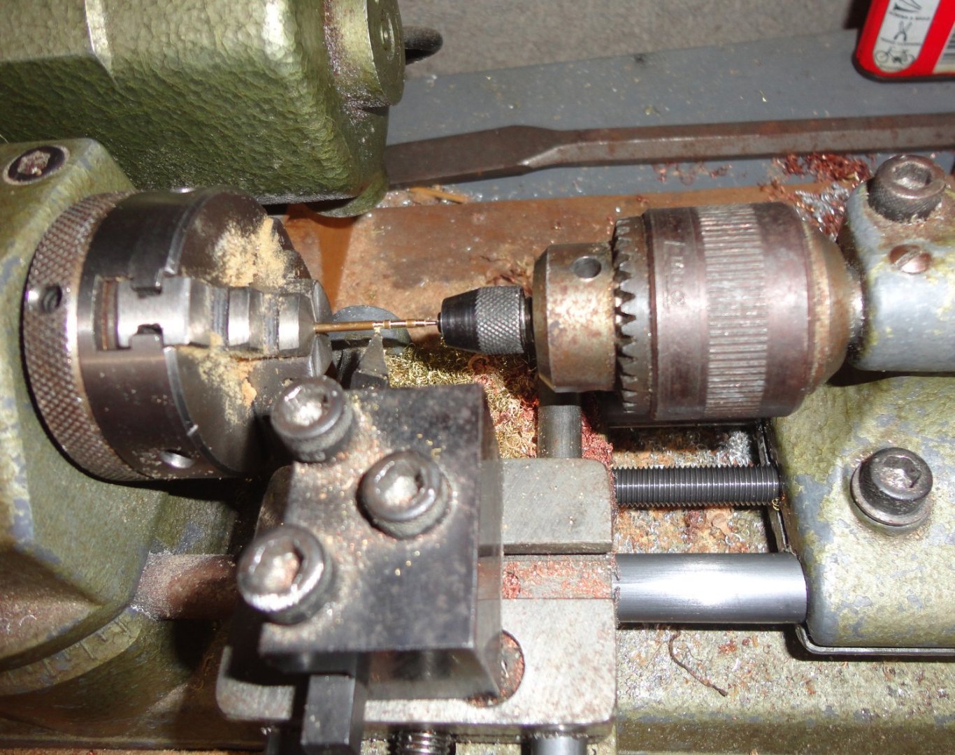
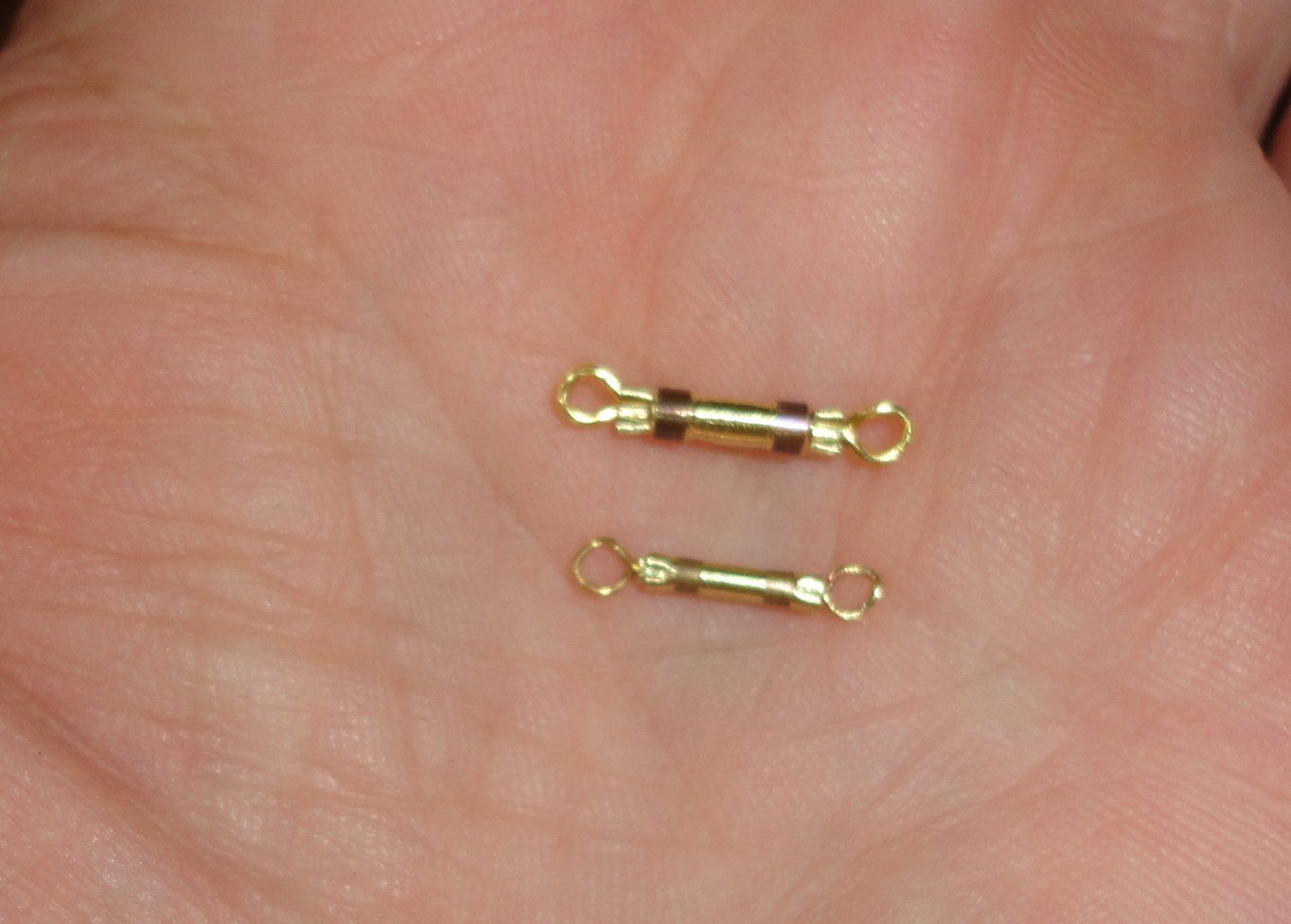
After some practice, the technique for making the turnbuckles was improved - and cutting them from pre-browned tubing makes for a nicer fitting. They're still a tad large for units aloft, so I went back to a Hobby Lobby for more stock and found a smaller size to try. Some finer brass wire was also bought. The eyes are made from 1 1/2" lengths bent around a fine drill bit as a starting point. This is a method seen elsewhere on MSW, but I'm picturing it here. Step 2 is to clamp in a vise and twist with the drill (prior to trimming off the end bits after forming). Turning smaller turnbuckle bodies is at about the limit in small size doable with my rig due to springiness, but I suppose smaller belaying pins might be done from rod held close to the chuck and cut with a form tool. 26 gauge wire was used for the eyes (versus 22 gauge for the larger turnbuckles), because the through hole in the 1/16" O.D. tubing is smaller than the 3/32" O.D. tubing. Below is the first trial part next to the larger version for comparison. Yeah, I'm still 'in the weeds' but plodding on with the prep work. In the photo below, the top group of turnbuckles are the 'learning batch' ... perhaps OK, but I might re-make them to appear uniform with the improved method batch near the bottom. On the lower right are the first pair of thinner fittings next to the larger size to be used to anchor the lower shrouds.


-
You're doing fine ... take all the time you need, which is my own style. I have an early, well-molded version of this kit up on the shelf for some future time (or perhaps to end-up with someone else when I'm gone), and have long thought on what eventual approach could be done with it. The Czech-made laser-engraved wooden deck topper was added to the box, as I've never been happy trying to paint plastic to look like wood - yet some have done pretty well doing just that. And starting with an unbuilt kit does not have the limitations imposed on restoring a previously built model, as you are doing.
- 44 replies
-
- 2
-

-
- Thermopylae
- Revell
- (and 3 more)
-
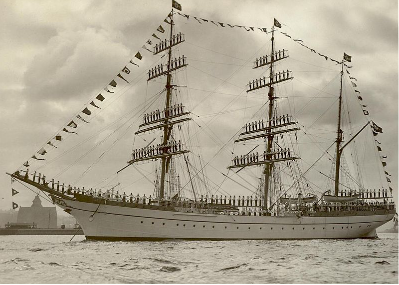
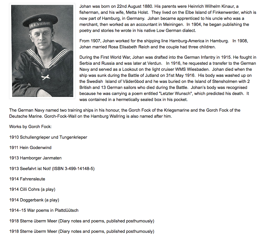
We've has some splendid weather of late (for August ... I feel sympathy for parts of the country plagued by fire, floods and earthquake - disasters of 'Biblical' proportions), that I've been working a lot outside when not working at the hospital. But the Gorch Fock I (GF1) is still on my mind. A nice photo was found with the crew standing on the yards for show ... brave and steady men. 'Don't know what the signal flags say given that the photo is B&W, German signal flags may differ from other nationalities, and the message would be in German. I can make out the Nazi flags atop the masts. So I looked some to find out more about the ship's namesake, Gorch Fock (a pen name, fock translating as 'jib'). 'Seems he was a playwright and poet who got swept up into WWI, as so many men did to their peril. So many artists, writers, teachers, scientists and men from all walks of life never made it home in that conflict ... and no one knew that even greater devastation lay further in the future. He appears to have been stoic about his conscription, and was steadfast in duty to the end, as were many of all nations involved. Ergo he must have been thought as an example of patriotism, as most nations honor those who die in service. I had a look at just two of his poems and did my own translation of them ... relying on what I can remember from HS and Collegiate (intermediate) German, plus a glossary. Much poetry (in my opinion the best poetry) has both meter and rhyme, and this makes literal translation tricky to do in order to give as much of the 'feeling' of the original into another language. So I gave my best shot. Segle, Hertz, mit allen Winden, Sail on, my heart, with every Wind, wirst nicht deinen Hafen finden. hope not your safe harbor to find. Hafen? Was soll dir der Hafen? Harbor? What harbor's meant to keep? Legst dich nur him zum Schlafen ! Just lay you down and go to sleep ! Segle, Hertz, mit allen Winden. Sail on, my heart, with every Wind. Das erste Kriegergrab am Wegesrand, At a soldier's grave by the road so grand, wir stehen mit der Mussen in der Hand. we stand with our kit and our hats in hand. Ob Freund, ob Feind der Tote, der da liegt, Whether friend or foe, he's dead where he lies, ein Blumenstrauss doch auf den Hugel fliegt. while a flower row up the hillside flies. Im Westen glimmt ein tiefes Abendrot; Off to the West glows a deepening red; wir grussen ernst und feirlich den Tod ! we earnestly, solemnly greet the dead ! Dann heult der Zug und es geht Russlandwarts ... The wailing train will to Russia depart ... Bleibst wie du warst, bleibst tapfer, du mein Herz ! Stay as you were, and be strong, oh my heart !

-
This is a nifty model and yours looks great. I suppose anyone who reads the available MSW builds will note the few challenging spots and be advised of remedial steps before going too far on the project. You are right that the guns look proper now, and sanding a bit of the bottom of the carriages is an effective 'slight of hand' that is virtually invisible on the finished model. I suppose that someone just starting out might 'lower' the level of the deck a tad by trimming the top of the bulkhead forms that the deck will be mounted on - or the needed allowance could be "split" between trimming the deck forms and building the bulwarks slightly higher (thus raising the gun ports just a tad).
- 144 replies
-
- 3
-
-

-
- Harriet Lane
- Model Shipways
- (and 1 more)
-
The photos you show of various steps are clear and instructive. Thank you. I can see now how drilling fairleads nearer to the lubber hole of the main top will assure that control lines from above will pass behind the point where the main shrouds (heading toward to the lubber hole) cross the lines from the lower deadeyes on the periphery of the top as they head down to the mast below. That way the route up the ratlines will be free of any other lines that might get in the way.
- 431 replies
-
- 1
-
-
- Flying Fish
- Model Shipways
- (and 2 more)
-
Chainplate & Deadeye Assembly Question
Snug Harbor Johnny replied to cardensb's topic in Masting, rigging and sails
A picture can be worth many (if not a thousand) words ... so a view of your components could be facilitative. -
Once more, some pictures new to me ... ferreting out "Getty" branded images (or any others that really are in the public domain - due to prior publication under the old laws - but have been since "copyrighted" by various organizations in possession of them). I have a collection of 'turn of the 20th century' post cards (most of them printed overseas, often Germany) with no copyright information on them (being ephemera at the time) - ergo they were public domain from the moment they hit the streets. YET, I'm seeing the same images on various internet sites where the holder has 'slapped' a so-called 'common law' copyright on the image ... hmmmm, perhaps they imagine that whatever spots, postmarks, folds, tears, etc. make them unique and fair game to anyone who wants to try and claim them as theirs. Yup, I've seen multiples of the same postcard in multiple sites ALL 'claiming' ownership. Not to worry, all one has to do is Photoshop out blemishes, foxing, postmarks, etc. and you have then created your own 'new' image ... and no would-be hoarder can lay claim to it.
-
Technical drawings & Dutch shell first
Snug Harbor Johnny replied to Jules van Beek's topic in Nautical/Naval History
'Chicken v/s Egg'? Chickens are birds, and birds are the living descendants of dinosaurs - ergo dinosaurs existed before birds. Dinosaurs laid eggs, ergo the Egg came before the chicken. Of course chicken tenders and McNuggets have egg in the batter that surrounds them ... -
Roter Löwe 1597 by Ondras71
Snug Harbor Johnny replied to Ondras71's topic in - Build logs for subjects built 1501 - 1750
There's a Gorch Fock in one display case there ... something I'm attempting to restore - estimated age 50 - 70 years. -
I've chauffeured the Admiral to another gem and bead show, and continued to scout out any possible fittings or findings while I was there. Some nice eyes with long shanks were found - to be used as deck eyes that can be pushed far enough into the deck of the solid hull (after pre-drilling slightly undersized holes) so that the tension will be enough to prevent pulling out under the slight tension that might be exerted by new rigging. I looked for what are referred to as 'bar spacers' to use as turnbuckles (as making them one by one is time consuming ... but then is there a shortage of time - other than waiting for the last call to sea?). Nothing was found, and an on-line search (including Fire Mountain - a major supplier) did not turn up anything suitable that was not gold-filled, ergo $$$. So I'm sticking with my present fabrication plan. Completely darkened turnbuckles caused the fine diameter differences turned on them to mostly 'disappear', given the small size and scale. So a small file was used to remove the color from between the collars meant to represent where a spanner would be placed during tension adjustment of a shroud. Uncolored assemblies were colored with fine paint applicators with the reagents in order, and that did darken the bands of those pieces. I happen to like this look better, so when more are turned from pre-darkened tube - the collars will remain dark and the minor diameters will have fresh brass exposed. The turnbuckles might just be painted white, as railings can also be painted white, but as said before, I like the look of brass (which will age gradually and get a patina) and paint often 'gunks up' fine details. A photo of some assemblies is below ... only 74 more to go !

-
Nice staining job. I've used Minwax for a long time, and even the relatively new 'reformulated' version (lower VOCs) gives about the same result. To lessen 'over absorption' (as the grain changes - especially end grain). I've often applied a light amount of colorless pre-stain wood 'conditioner'. This lets the wood 'drink up' some vehicle so that light application of the colored stain goes on without over-coloring. One can always go over the wood again after some drying to darken, but once over-stained you can't lighten it except (perhaps) by sanding. Your rope looks good, and will further enhance your model. Thanks, so much for the great photos and diagrams of the 'Polar' decking. THIS is just the sort of information I've been hoping to see at some point, and will definitely influence anything I do in future on this ship. Also, that's a GREAT capstan ... and I wonder if the maker would be willing to sell some to members of the 'Endurance club'. So far, I've assembled some of the items that might be considered a 'kit enhancement' set that include things like brass 3D stanchions, a two-bladed prop, tiny jackstay eyelets, home-made rope (can always be bought), better deadeyes (of scale size out of walnut), etc.