Snug Harbor Johnny
-
Posts
1,501 -
Joined
-
Last visited
Content Type
Profiles
Forums
Gallery
Events
Everything posted by Snug Harbor Johnny
-
 If you are using 'real' metal 'plates', adhesion problems on the underside may be due to a smooth surface on the metal. Many types of glue hold much better to a surface that has some fine roughness (referred to as "tooth") to it. That makes for a better 'mechanical' bond. Wood generally has this property due to the wood fibers, but that can be negated by 'filling' the pores and crevices with sealer and turned into a smooth, glossy surface. Then one has the problem of trying to glue TWO smooth surfaces together. Going over the hull area to have plates glued with a fine sanding paper will impart the necessary "tooth" to that side. The plates (while flat) before forming can be roughened in a similar way, or with a fine jewelers' file. Then both surfaces will be more 'grippable' by whatever glue you are using. Many have used copper 'tape' using a variety of techniques found here and there on the forum, but I wonder about the long-term stability of 'soft' or contact bonding agents ... they may peel away after enough time goes by.
 -
Great Scott, that's a nice little boat ! 'Love the Martian - a miniature of the one Bugs Bunny always foiled.
- 56 replies
-
- 3
-

-

-
- Sea of Galilee Boat
- SE Miller
- (and 1 more)
-
I totally get what you're saying about the 'order of assembly' of various details (like the capstan). Now on every build (of anything), I'm straining my brain to 'see past the instructions' (having read all of it at the outset) to see how everything has to come together - and what should REALLY go in ahead of something else. This stretches out a build, but avoids (or at least limits) the frustration of un-doing anything or working harder to fit something in. Yeah, that's called 'working smarter, not harder'.
- 59 replies
-
- 1
-
-
- Santa Maria
- Artesania Latina
- (and 1 more)
-
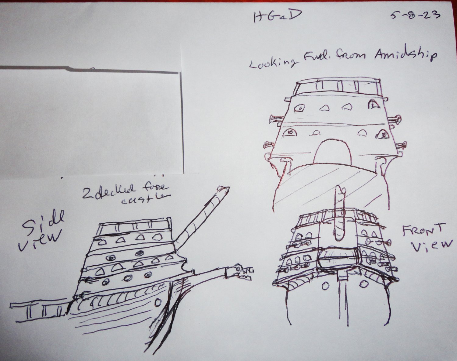
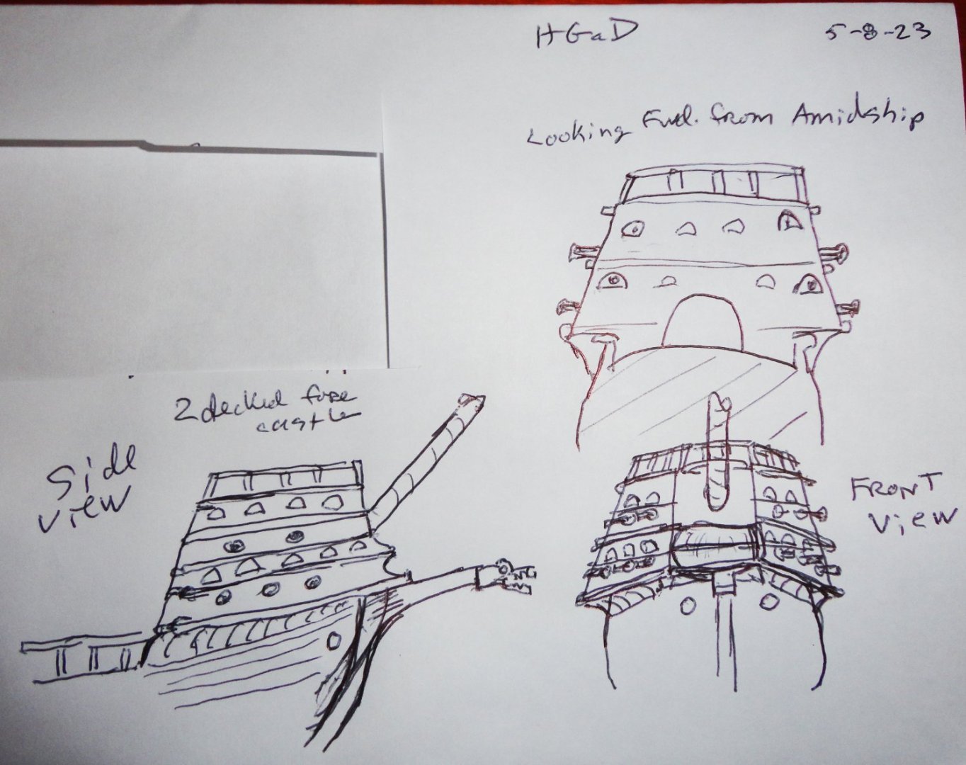
Thank you for all the info in your reply ... This new distraction is a break from the Vasa for perhaps a couple weeks. I know that 'conclusions' are hard to draw from the Anthony roll depictions, and that the is a certain amount of subjectivity to what one thinks he's seeing in the drawing. Yeah, and most of what has survived are mostly stern quarter views. But ... my eyes think they're seeing at least some sideways cantilever' at the forward break of the 'waist' (exposed weather deck) - the back face of the fore castle. It's the 'shading' under the Anthony fore castle going forward from there that also gives the impression of 'overhang'. I'm no artist, but I've made a quick (and crude) sketch (not even as good as the Anthony roll) to try and depict what I'm seeing. My pre-1536 concept is a 2-decked fore castle with railings on top that will have shields affixed to said railing. The stern castle would have 3 decks with railing (plus shields on top). I figure when modified in 1536, the stern castle was likely reduced for a 2-deck configuration, then a partial 3rd 'deck' built onto the fore castle in the back half (per Anthony). The pre-1536 would not have top gallants. I'm a bit overwhelmed at the TOTAL dimensions of the model 'out of the box' ... like 50" stem to stern pole and as high from keel to pennants. It IS a whopper of a project, and when I look at the size of the brass turned guns, they are really at a smaller scale. The likely solution is to make all new framing at 1:88 scale (halfway between the 1:75 of the kit - apart from its length, which is more like 1:65 - and the 1:100 that I'm used to working with. The provided cannon seem consistent with an adjusted size of hull at 1:88. I'm mindful of the display case to protect the finished model. As supplied, over 50 sq. feet of glazing material would be needed for the larger size, versus 27 sq. feet for the adjusted size. I'm also mindful now that Australia is in a much different time zone (our days and nights are effectively reversed) - so please forgive my earlier oversight time-wise.
-
Plastic or Wood models? Your Favorite?
Snug Harbor Johnny replied to Bill97's topic in Modeling tools and Workshop Equipment
I find that research 'old kits' and looking for them (often at a bargain price) on the internet a pastime ... 'Guess contemporary catalogs - like the gardening ones with pictures designed to make the gardener 'green with envy' - are a way to generate interest. Did that start with the Sears "Wish Book" - with all the Christmas goodies for the entire family that came out before the end of Summer ... in time to start all those lists for Santa ! -
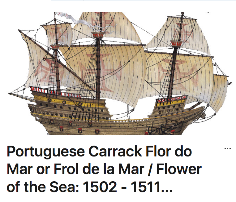
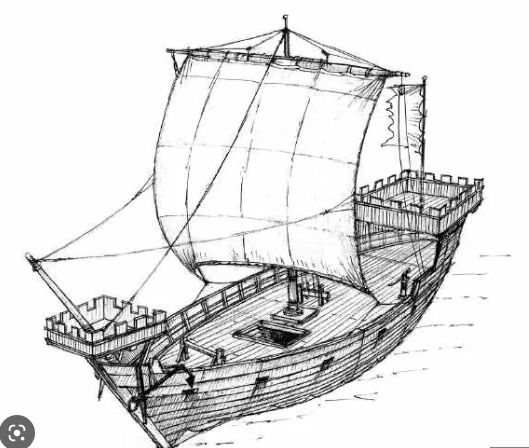
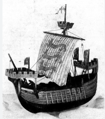
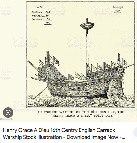
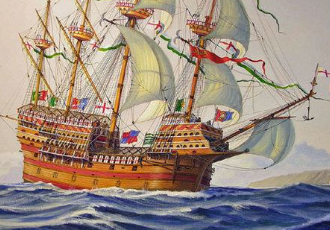
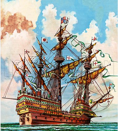
SO far no opinions offered, so I'll have to be 'Captain of my own ship' ... subject to Admiralty directives. 'Seems the HGaD represented the cutting edge of the naval battleship at the time in so many ways ... and the MR was the immediate precursor (so its lucky we have what we have of her). A very notable thing was the bow shape and lines BELOW the waterline, which were anything but 'bulbous' as earlier carracks often were. A gentler transition to the 'fatter' middle sections would lessen resistance and provide speed superiority over any comparably sized (or lesser) vessels. This is a key tactical advantage since (after battle assessment) an opponent could not 'get away' if the decision was to engage - nor could an otherwise superior force catch-up if the decision was not to engage. The advantage to the development of a 'square' stern was to support a larger stern castle as well as creating room for ordnance much further back in the hull (allowance for recoil and reloading requires enough breadth on the gun deck) - and a stern rudder w/tiller saw the elimination of the vulnerable steer-board (on the starboard side). The lines in the stern had to be modified so that the stern rudder would be effective - simultaneously providing a speed advantage as strong eddies were mostly eliminated Perhaps this inspired some streamlining in the bow. The full-round (or 'apple') bow would return as 'Castles' disappeared and space was needed for heavy ordnance to be in the forward part of a warship, and more displacement was also needed to support the increased weight in that area. So you see, form follows function - which is at the core of my considerations about the HGaD's for castle shape and size. Most contemporary depictions are from a stern aspect (or profile), and many models have defaulted to a 'pointed' forward castle. There is another reason why this would be a disadvantage ... as the sides go down to a 'point', there is almost no internal space for anything. Carrack castles started out as mostly square fighting platforms on either end of a double-pointed hull. There ARE pointed forward castles where they are 'open- topped fighting spaces. In the case of the HGaD, a fore castle starting out at least a little wider than the gunwale beam would serve better as a 'mini fortress' if the forward face were not so narrow. Below are some images for comparison: The earliest castles: A flat forward face (but no overhang) A 19th century engraving depicting what sure looks like a relatively wide front-faces castle: A more modern piece of artwork: Once again, these are different opinions through time - so the concept of 'form follows function' should be my guiding principle whatever route I go. BTW, here's a nice stern view of a model showing the narrowing of the back ... but the shape goes too deep to afford the 'clean' water needed to make the rudder more effective, as the reference books on the recovered MR show. I found a good enough piece of birch plywood (2' x 4') just a few thousandths over the Sergal kit frames. There's plenty there to make all the modified frames I'm likely to need. I searched through the whole stack at Home D to find one that was flat enough. Regarding the Sergal frames supplied, I noticed that the keel piece was kinked enough to be not good to use as it sat - so I got out my iron (set on high for linen) and used dry hear and cautions counter bending on a wooden work bench to reverse the kinks. It worked! I've used wet heat for 'solid' (non-plywood) stock and dry heat for plywood before (it can loosen the glue bond) - and wrecked pieces (some time ago) while learning. The deft touch and 'wood sense' not to over-bend (once learned) is helpful. It's like when I was a kid and 'stripped' a metal nut when over-tightening on a bolt. That helped 'calibrate' me how not to strip a nut - and the lesson has stayed with me all the intervening years.
-
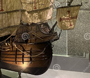
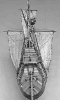
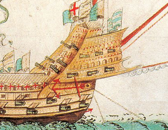
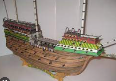
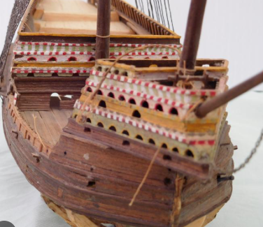
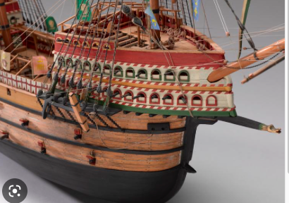
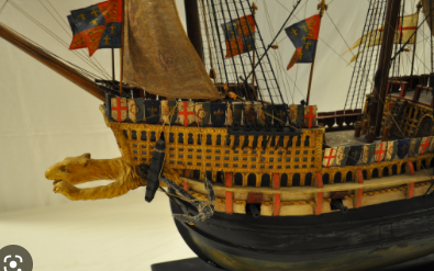
Steve, I agree ... but there are certain 'details' that are of interest, as there are things that any attempt to picture the GH will have unique features and some other features found in other art. Now there is ONE feature that draws my attention from the Anthony Roll, and that is the 'overhang' of the fore castle that shows a curved support. Whereas the view 'from the deck' looking forward in the Anatomy Book on the Mary Rose (MR) shows the base of the fore castle flush with the hull (thereby making for an distinctly 'skinny' shape not seen in Anthony'd depiction of the MR) one can see in the image section below that the GH (or HGaD if you prefer) forecastle has a WIDER base than the gunwale below. Some models have this overhang, while some do not. Many of those that do, have a flat projection, that is, no curving planking from below. The Sergal kit has the curve underneath ... but also an overly wide 'snout' where the bowsprit emerges (more on snouts later). There would be a distinct Military advantage to having the fore castle wider at the base than the gunwale leading up to it. 1.) Just like in land forts that were beginning to evolve (eventually leading to the 'star' fort), having a section of defensible wall at an angle to a main wall will allow defenders to fire down at attackers who may have been able to get up to the main wall - thus would be underneath defensive fire from that wall (unless someone exposes themselves by leaning over the main wall). The guns in the Anthony image (crude as they may appear) represent anti personnel guns along the edges of the fore castle that hang slightly over the hull to afford those weapons a direct line of sight to small vessel that might get close to the ships side - and NOT (as some have supposed) meant to fire into the deck area to repel boarders, as such fire would harm friend as well as foe. 2.) A wider for castle is needed to have enough room inside for sufficient attack/defense personnel, and as the forecastle has to taper anyway toward the point of the bow, one needs to start wider rather than narrower. Soooo, the reason there is a CURVE under this 'overhang' is because there are knees beneath (attached to the futtocks there) to prevent sagging. This 'under-curve' lessens as the bow tapers, so that the overhang in the forward part of the forecastle projecting beyond the bow IS flat, but supported by the extension of the keel (my terms are lacking right now) sprouting out from the bow (that is seen just under the bowsprits of clippers) that is NOT shown on the Anthony picture - also missing is a dragon or monster head on the end of said projection. Now I suspect (just my opinion) that they may have had multi-hole toilets (with so many men, there might have been a three-holer on either side of the keel ... but no Sears catalogs yet) in the front part of the fore castle where the 'waste' would just drop below through gaps in the short support beams or through holes if the understructure was otherwise planked. BTW, I've found a 'pirated' version of the Sergal GH (well, a duplication of the design) in a heavy 'paper' kit listed in some ads as 1:100 available now from 'Eastern Europe" ... Below is an image of the Sergal (with it 'gallionization' previously mentioned). The under curve is not easily seen in the picture, but it's there - as well as to overly wide 'snout' ... something I have to change. The treatments of the tops of both castles need to be different to better conform to contemporary images. There is an image (artwork) where the under curve is better seen. Now a good compromise in a flat snout can be seen below ... an all to familiar build on our forum. Compare that with a 'pointed' version - that its own problems relating to accommodating the bowsprit. And there is a model that tries to more closely resemble the 'Embarcation' picture (with all its 'cloned' ships having the same prow beast with extended arms) ... but does depict the shields seen in the original art. Any input, opinions, etc. would be appreciated. There's SO much to think about, and another challenge is making replacement frames to provide more accurate line (similar to what we know the MR had) ... just as we're beginning the yard-work, exterior maintenance, Honey-do cross-offs (thats really a game of 'Whack a Mole'), etc season. Well, one can cut all sorts of trial frames and pieces as time permits. There is still the possibility of doing it slightly 'less large' ... we'll see.
-
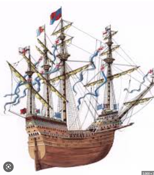
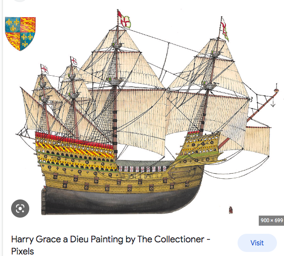
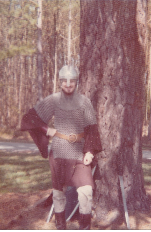
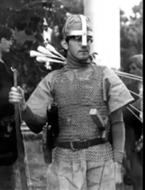
I've done a bit of looking, and (aside from Steve's fantastic model) found two relatively recent depictions of the GH ... there are elements from each I like, so what I end up doing may be an amalgamation from all 3 of the above. Doing careful measuring and scaling, the conclusion is that the Sergal kit may not be far off in OAL (less bowsprit) after all. The two images below both have a ratio of length at waterline to maximum beam of about 3.42 - 3.44 - considering the larger size and tonnage (originally as high as 1,500 per some sources, reduced in 1536 to about 1,000 - 1200 ?) the higher ratio seems justified. That would put the OAL (less bowsprit) scaled at 1:76 (all other calculations of the model's drawings and fittings fall into a 1:76 - 1:80 range) to about 33.4" compared to just shy of 35" as drawn. Perhaps discretion may be the better part of valor in this case and I may go with the provided hull ... the largest I've attempted so far, but by no means unusual in our hobby. For instance, all the Cutty Sarks at 1:75 (215' on deck) will have that dimension represented by 34.4", with the entire model over 40". The 1:75 Vasas have nearly 32" hulls (less bowsprit), and there are two big version kits at 1:65 ... with nearly 37" hulls !! ... 'Chunkey monkeys to be sure ! I've started to cut out a couple of frame pieces needed for dry fitting - and also to figure out how I'm going to re-engineer the fore castle. This will be something to be done "hands-on", versus trying to pre-draw everything. Cardboard templates may come into play, and once worked out this module can be set aside until the rest of the beast if dry fitted. I don't want to think about glue until I know everything is going to fit correctly. Some thinking ahead before even cutting out pieces showed that a modification for two frame pieces would be better (considering what would have to go on later) even if the kit were to be built as provided (which I knew I wouldn't do). As mentioned before, Sergal (in the 70s) had "galleonized" the GH ... (that's term I coined as I love word-play in the English language ... including puns). So the process of 'galleonizing' would be 'galleonization'. Hmmmm, so the process I'm involved with now is 'reverse-gallionization'. Like was exclaimed in the movie 'The Mask' , "Somebody, STOP me !" So here (at last) is where my occasionally verbose review of the subject kit should end, as I've now 'cut some wood'. 'Look like I'll be doing some on this WHILE going back and forth trying to do more on the Vasa. But they are only about 100 years apart, and the masting/rigging will not be entirely dissimilar - actually relatively similar. The next step (when there's something to show) will be to start a build log - which I hadn't planned on doing for a while. But when the 'bug' bites ... BTW, Steve, I also did a few Hastings re-enactments a rowdy bunch of us would do annually on the hilly Chapel lawn of the University of Maryland. We also would do Stamford Bridge elsewhere as a prelude, as well as march in parades and hold feasts (the beer would flow).
-
Your work with this plane takes me back to building similar models as a youth, alongside my dad who built large RC planes. Nicely done.
-
'Love the detailed pictures that will help me with my 'somewhat larger' project at 1:78 ... You've done a SUPER job, and I marvel at the tiny figures you carved. I think I'll be able to get some pre-made figures at 1:72 scale that will fit in.
- 740 replies
-
- 4
-
-
-
- Tudor
- restoration
- (and 4 more)
-
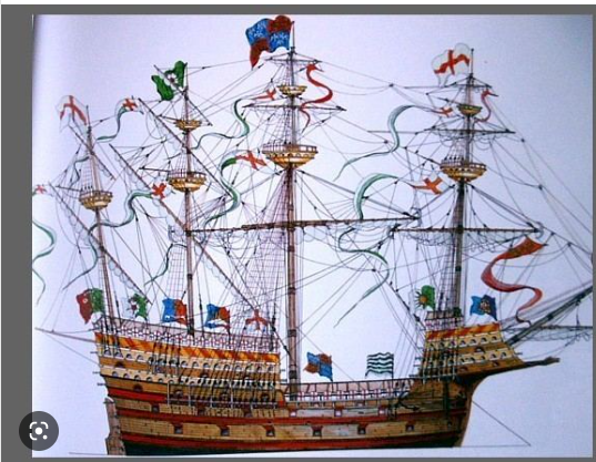
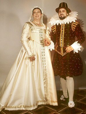
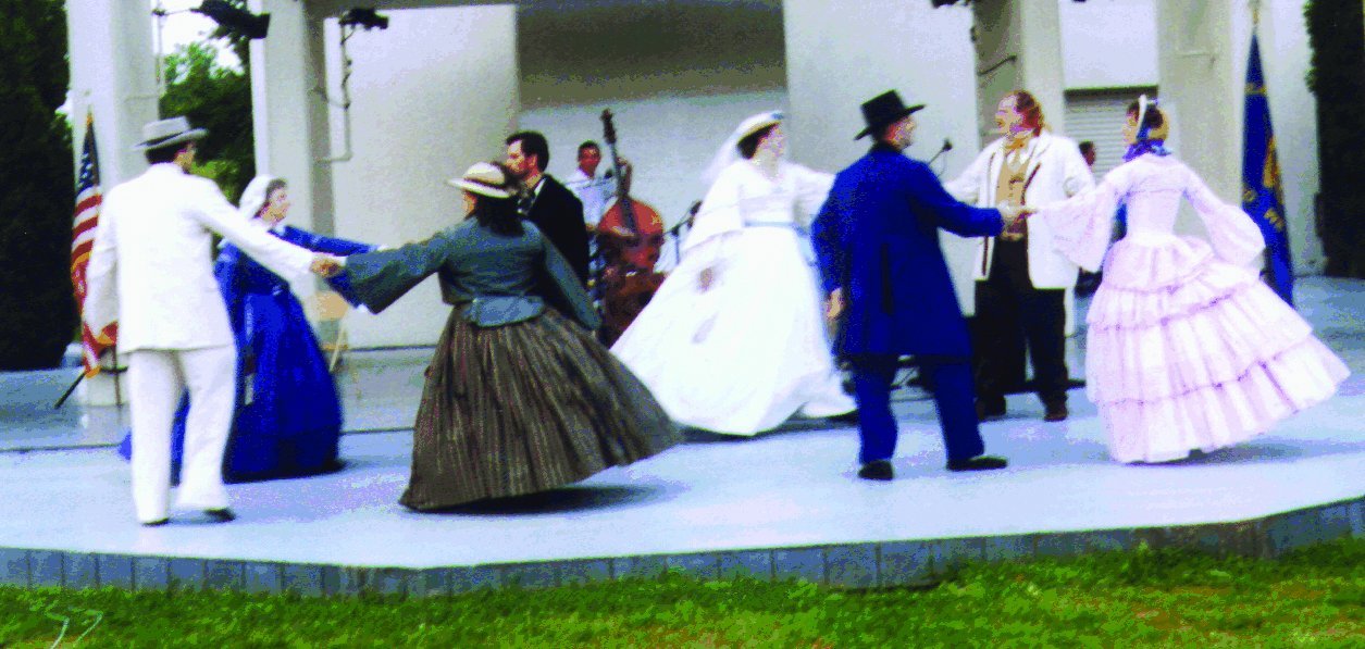
Ahoy Steve, 'I forgot to address the color & decoration scheme you inquired about. I'll have to give much weight to the Anthony roll, yet I want to depict the pre-1536 version ... actually as it might have looked being prepared (sans sail cloth or netting) prior the the 'Cloth of Gold' voyage. The diagonal design across seems to be diagonals of red and yellow separated by white. And there should be shields atop the castles like in the picture (as well as the 'wedding' picture depicting the same time) - and the heraldry used is likely accurate, and 4 principal designs are used in sequence (one can also see a 5th design in places). I'll want 3 full stern castle decks and will not have top gallants. Some good news - in that the vertical measure (keel to waterline, waterline to weather deck and the relationship of the lowest row of gun ports to the waterline) are all consistent and at the desired scale of about 1:78 (+/- 2) - so its only the overall length that is just about 4" long. This means that I can likely engineer a way to shorten just the stern area without affecting all the stuff forward of that. The exception is some MAJOR re-work of the fore castle geometry, which constitutes a 'module', so can work on that (and rework it) until I get something that looks right. The framing of the hull is like a 3D jigsaw puzzle, and I've not seen anything quite like it. There will have to be a LOT of thought to strategize how the build will go 'from the guts out', and I anticipate a number of months (on and off) fooling around with it as I still want to make foprward progress with the Vasa.
-
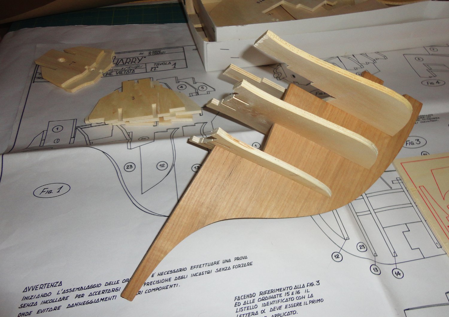
Rick, I've had a chance to look at the components more closely - and was wondering if the frames had been CNC nilled from stock, yet a mill doesn't make square corners milling from the face. More clues came when I found several thinner ply pieces still in 'matrix', and they were definitely die cut ! So my guess is that the major frames were also die cut - super nice with only slight teeny vertical striations where the blade(s) descended. So there was definitely dedicated tooling to make the limited run of kits - ergo fewer units to spread the development and tooling costs - ergo my initial estimate for retail of something comparable in quality in limited quality was low - and should be bumped-up to something like $1,200 today. So the revised estimate (unless someone can find catalog data from the 70s) of the original retail may have been in the $300 to $400 range - a hefty price for a kit even then. The plywood has three plies plus a face veneer on either side ... really nice stuff. I trial fit some pieces at the bow, and they are nice and snug with no 'wobble' - really precisely cut and a modeler would have a lot of trouble to scroll saw them so perfectly. Below is a dry fit of a few pieces - also one of the printed stock that I will have to cut out myself ... could be the tooling budget reached its limit. Now it appears that the fore castle is really different from the Anthony roll and other contemporary art. My first challenge will be to alter or re-fabricate that entire sub assembly before going any further.

-
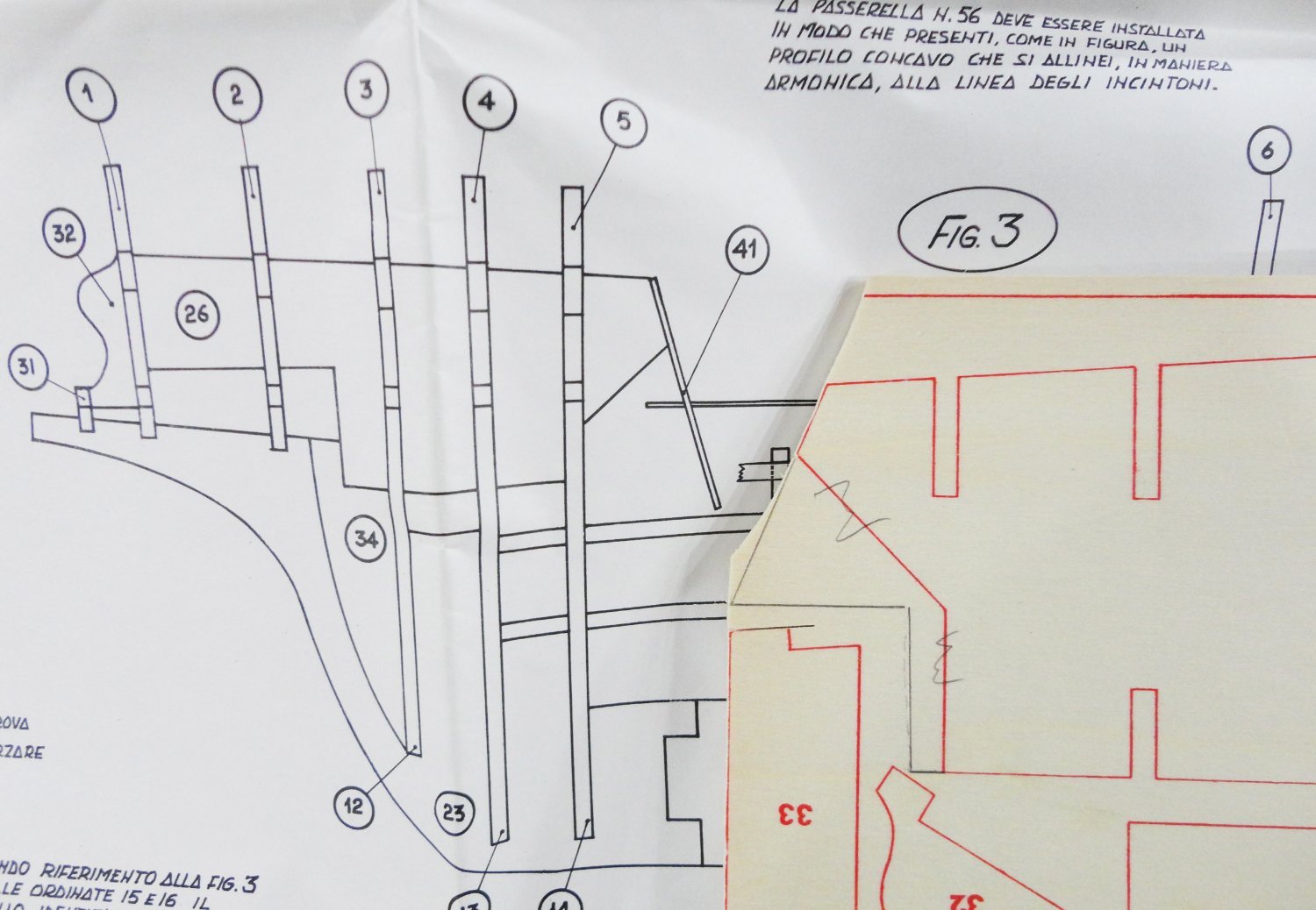
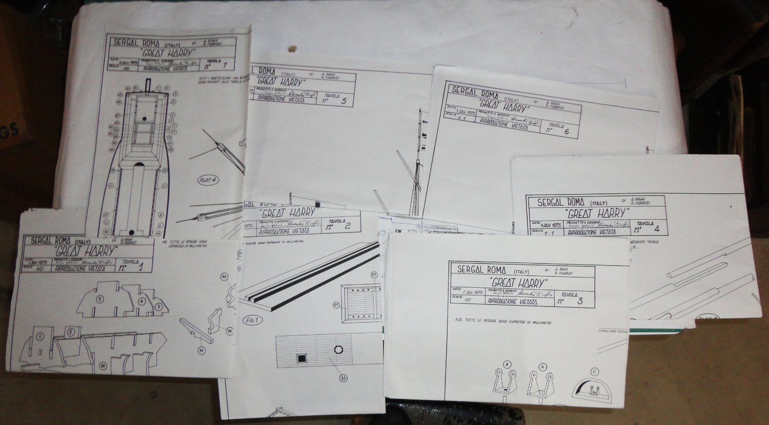
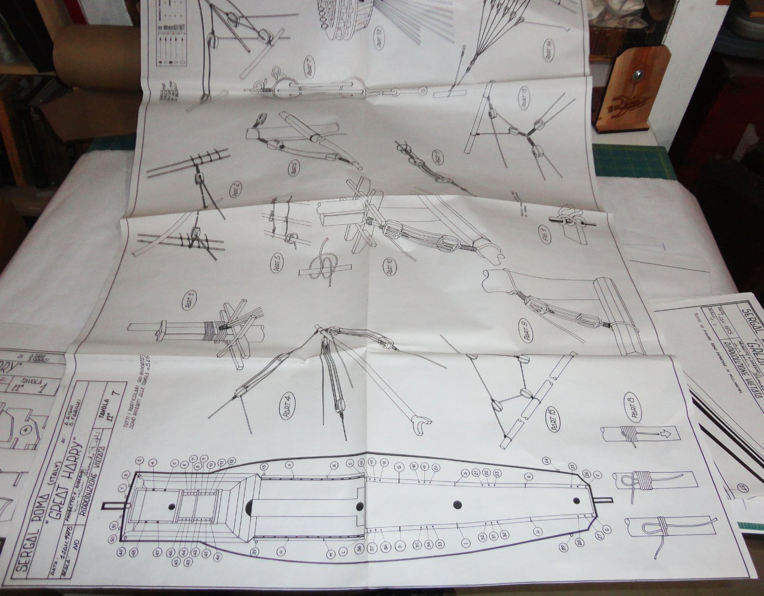
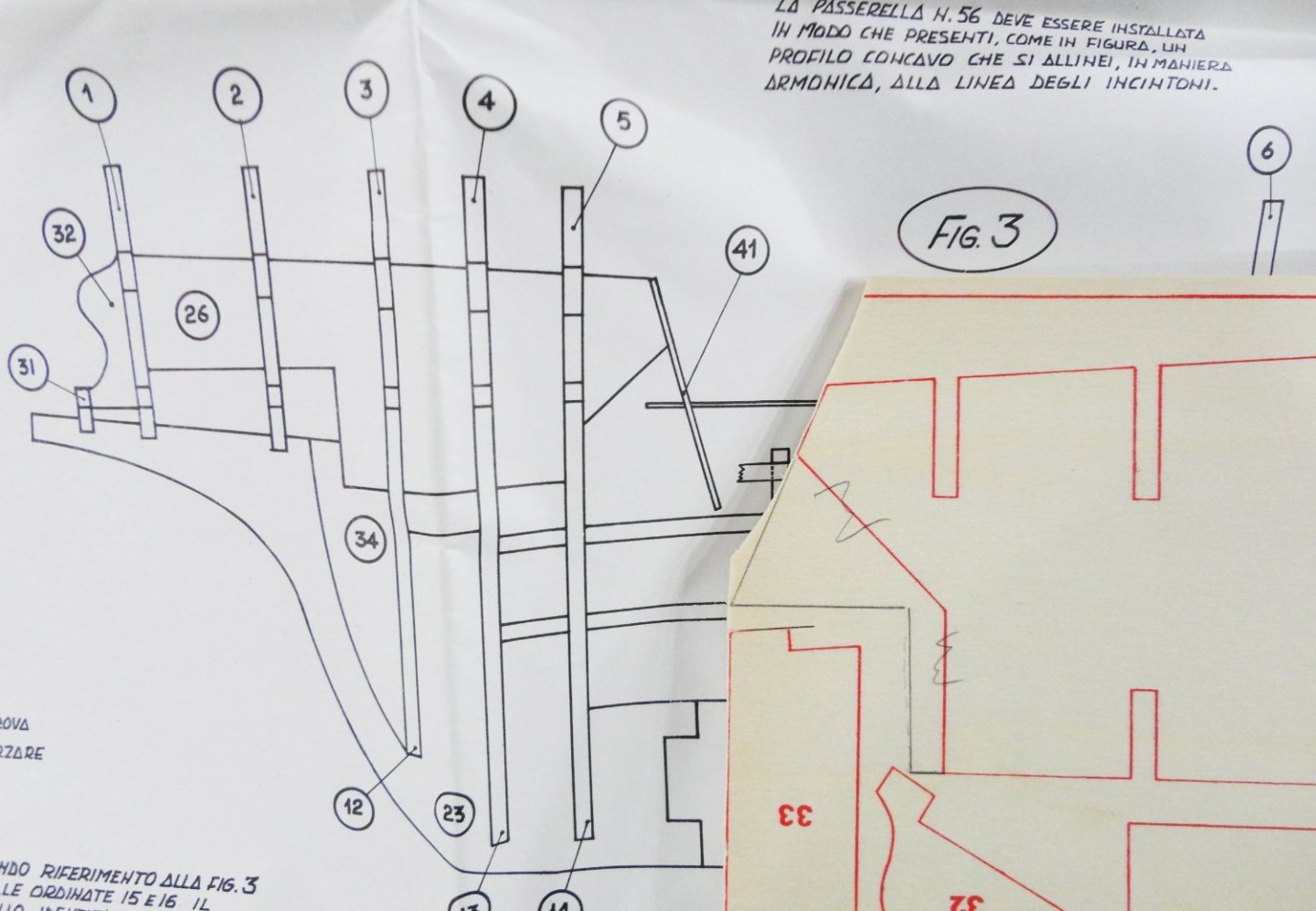
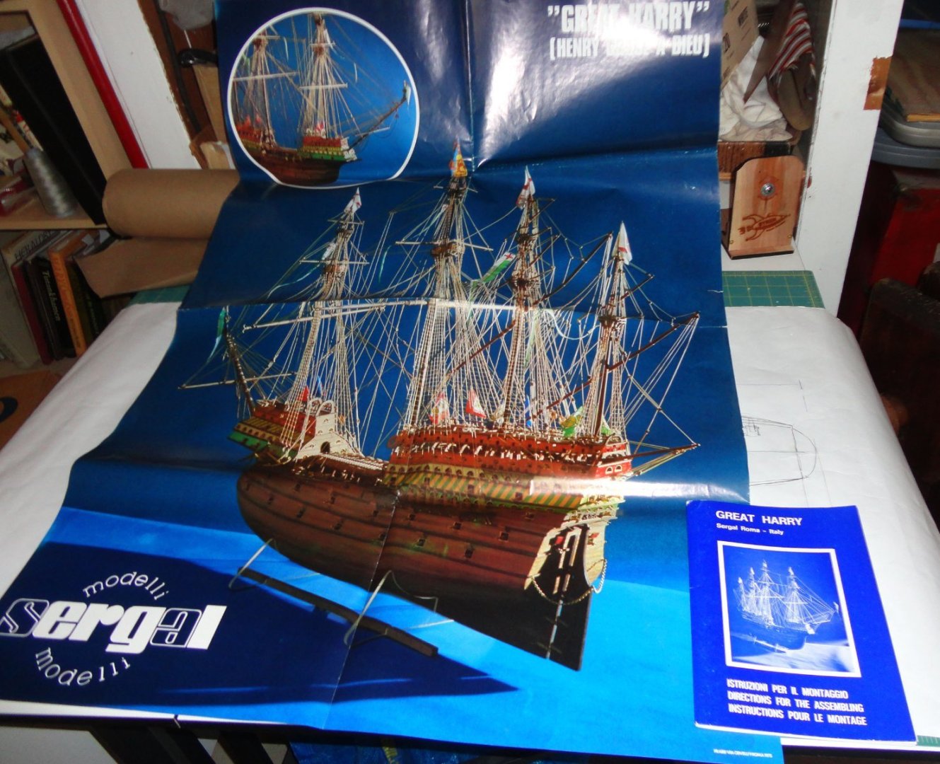
Greetings, Steven ! Since this is the unbuilt kit review section, the build won't be posted on this thread. I wasn't planning on doing the Great Harry for some time, but my imagination is stoked a bit ... and at the very least I want to see how I can reduce the length a little to more accurately fit the proportions (waterline length - which is essentially 'between perpendiculars' to maximum beam) of 3.25 like on the Mary Rose. For that I'll have to dry fit the extensive framework provided to see where pieces can be sequentially removed from the keel pieces (its not a single piece anyway) to change the spacing between frames - and also there is the need to alter the shape of the frames to conform (more or less) to those of the MR. The kit ratio is 3.6:1, and it might be hard to change that much now that I'm looking at the 'honeycomb' design of how everything goes together. We'll see ... 'Seems there was an 'evolution in this ratio, where earlier Carracks were around 3:1, 3.25 for the MR & GH, 3.6 or more Galleons and up to 5 - 6 in the Clipper era. There are things modelers of early ships don't have to deal with like jackstays, studding sails, belaying pins, metal railing & such. I'm seeing sails as problematical, especially if set versus furled. Fore one thing, set sails tend to block the view of the hull and deck details depending on the point of view. Since a majority models traditionally were not fitted with sails - at the dock or in the harbor so to speak, there is a lot of running rigging that can be omitted - reducing the 'spaghetti ' of all those lines running everywhere (my taste, though) - especially with later ships. As an addendum to my kit review, I note that there appears to be a sort of building jig (if I'm not mistaken), but one must devise a suitable stand for the ship. The one in the wall poster is shown with acrylic pieces supporting the hull - definitely NOT included in the kit. Looking at the drawings (which are massive in size - a little too big for convenient handling), the notes are in Italian, so I'll have to get out my Google translator to see what they say. As mentioned earlier, the 'instruction' book is merely a gloss - and even in Italian, the notes on the drawing are brief. Ergo general experience will have to be relied upon, as well as current source books. There are several cloth flags (not pictures in the review) that are printed fabric. They seem OK. Some other quirks came to mind about the box contents, but since my RAM often dumps overnight I can't recall those observations. I've always been process-oriented and I focus on the problem at hand and how to solve or work around it with the materials and tools available. Later, I often can't recall how I did things ... like a few years after making a scratch-built 6" reflecting telescope, I wanted to do a larger one. So it was back to the books to refresh myself on the grinding, polishing and testing procedures (which are very fussy ). A couple years later I did another, and had to re-aquaint myself with the procedures. Everything 'came back' alright, but not without consulting notes and references. Thank the Lord that there are some things that automatically 'stick with' you once learned, like riding a bike or driving a car.
-
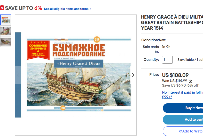
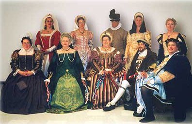
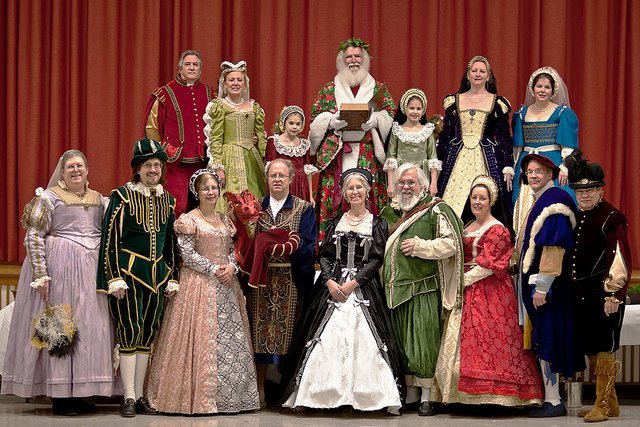
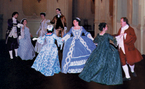
Ahoy, Rick !! And thanks again for informing me of this consignment item ... which happens to be of interest, in part since the Admiral and I have long been historic re-enactors in time periods ranging from Italian Renaissance, Tudor and Elizabethan England, Colonial, 19th & early 20th century ... eclectic, no doubt. 'Guess I'm a learning, costume and dance junkie. The inflation factor going back to the late 70s (USD) is easily 4 to 1 (400% cumulative inflation - Gee, guess the 2 long-term hazards for personal savings are inflation and market risk ... how do you balance them? Our answer in semi-retirement is to continue to earn an income stream by part-time work and self-employment). A new kit like this today (modified to reflect current information, and less reliance on large format drawings - made up for by better instructions/photos a-la OcCre) might retail around $900 since there are not extensive carvings and complicated fittings like on the Sovereign of the Seas or the Vasa. 'Scaling back to late 70s prices and you get $225. What the heck, I might as well add a few pictures of my historical interests. I can't lay hands right now on my best photo in Henry VII finery (like in Henry's famous portrait), but I'm seated showing my order of the garter in one picture of our dance group friends in the Tudor period. Bvr Bllrm 150dpi_layers copy
-
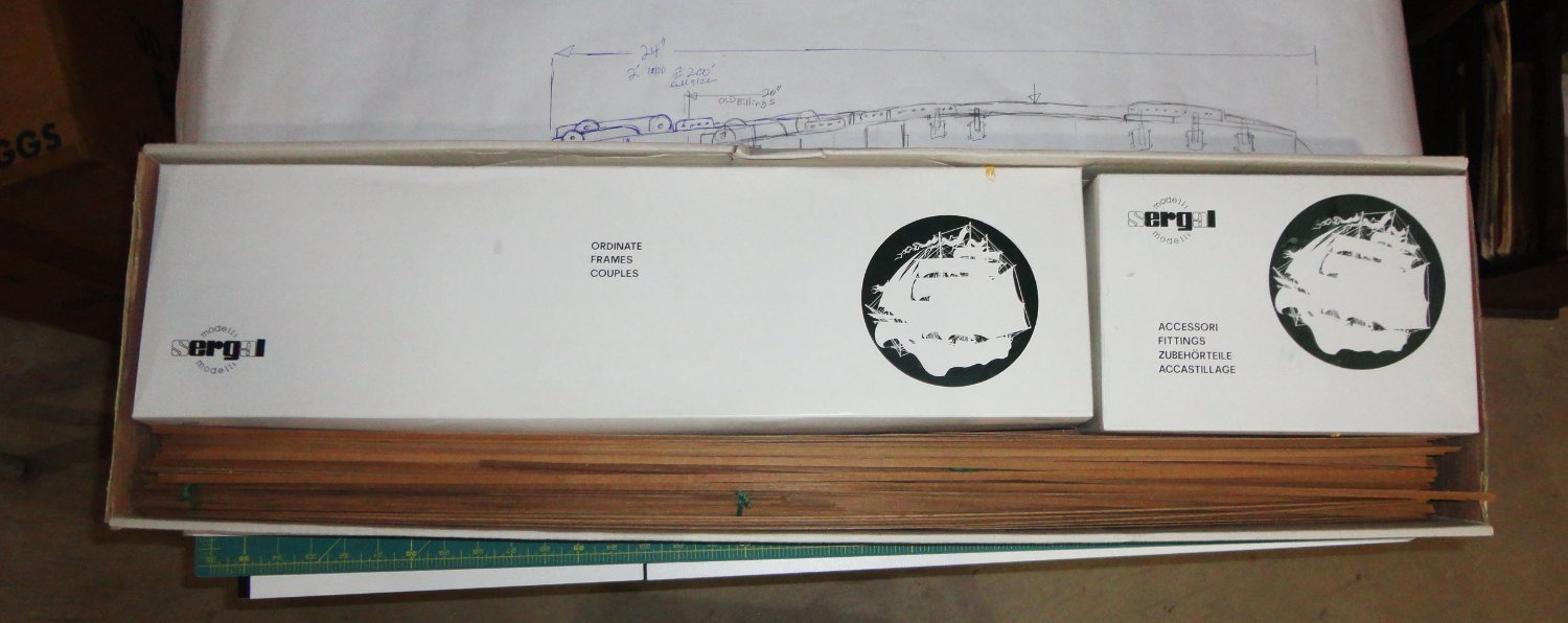
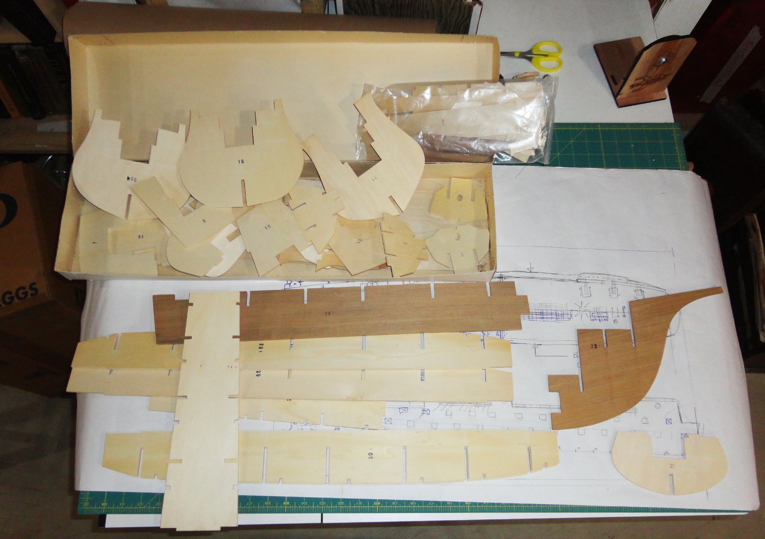
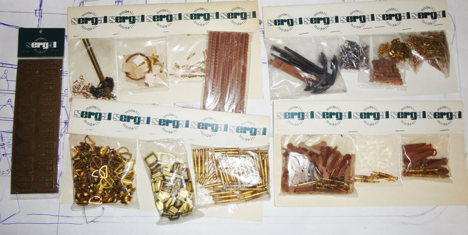
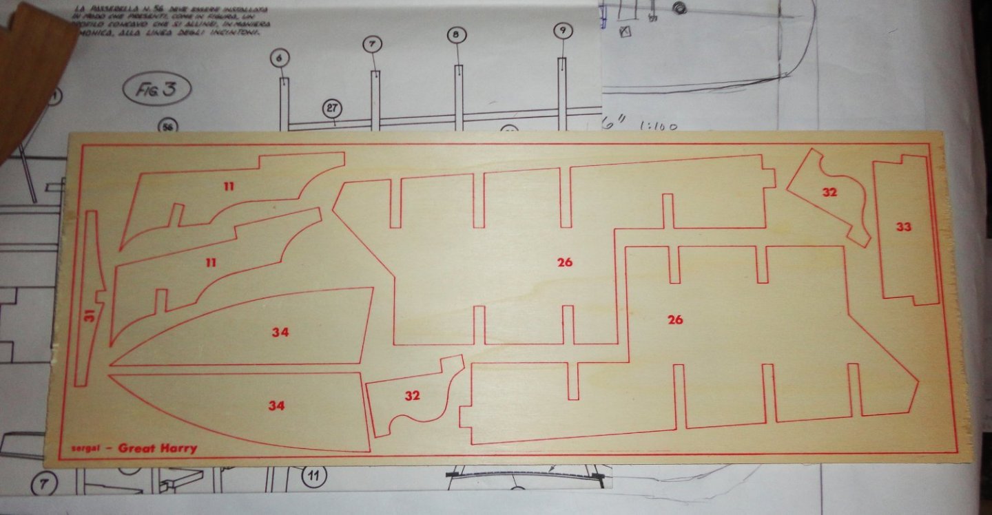
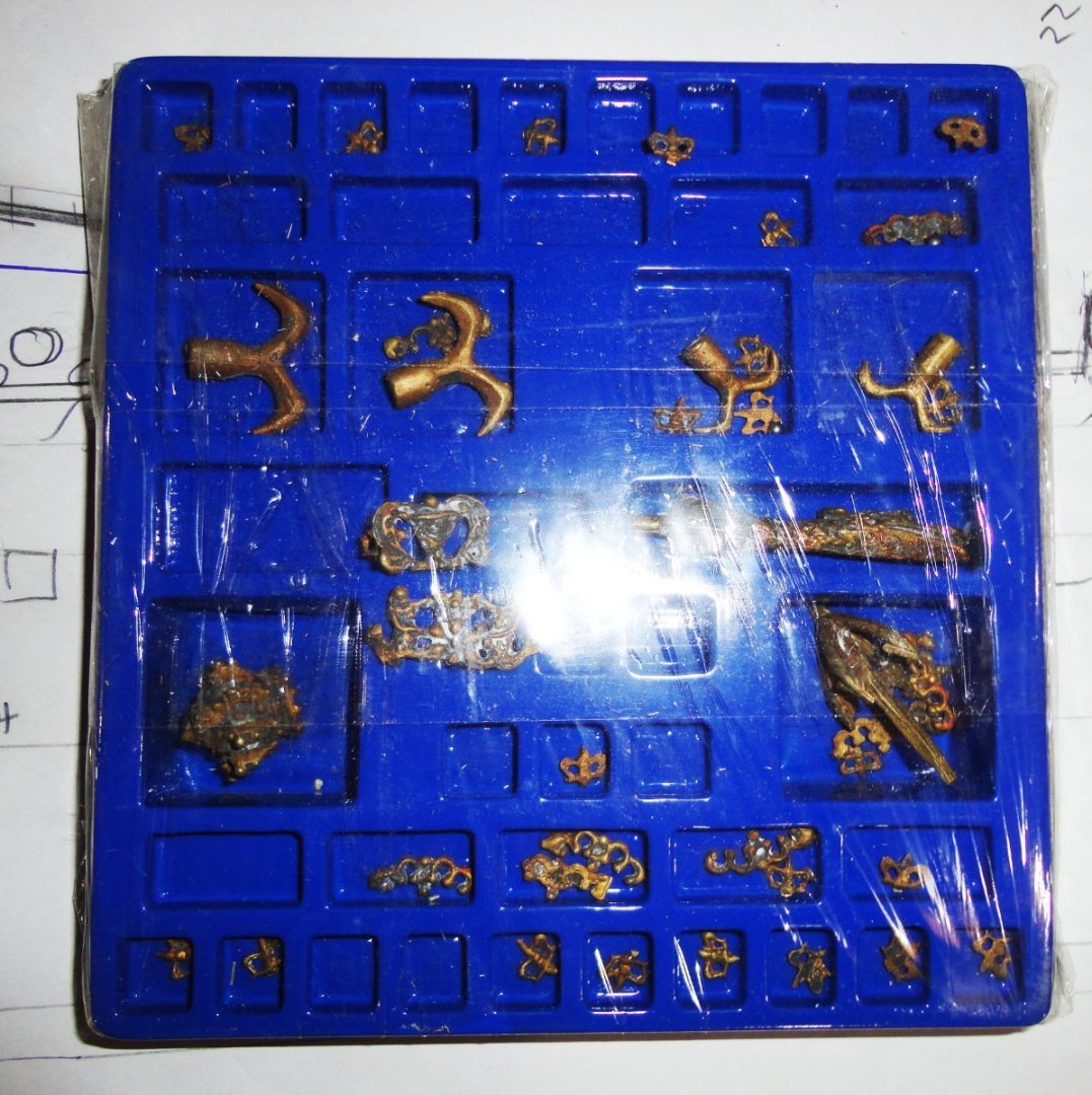
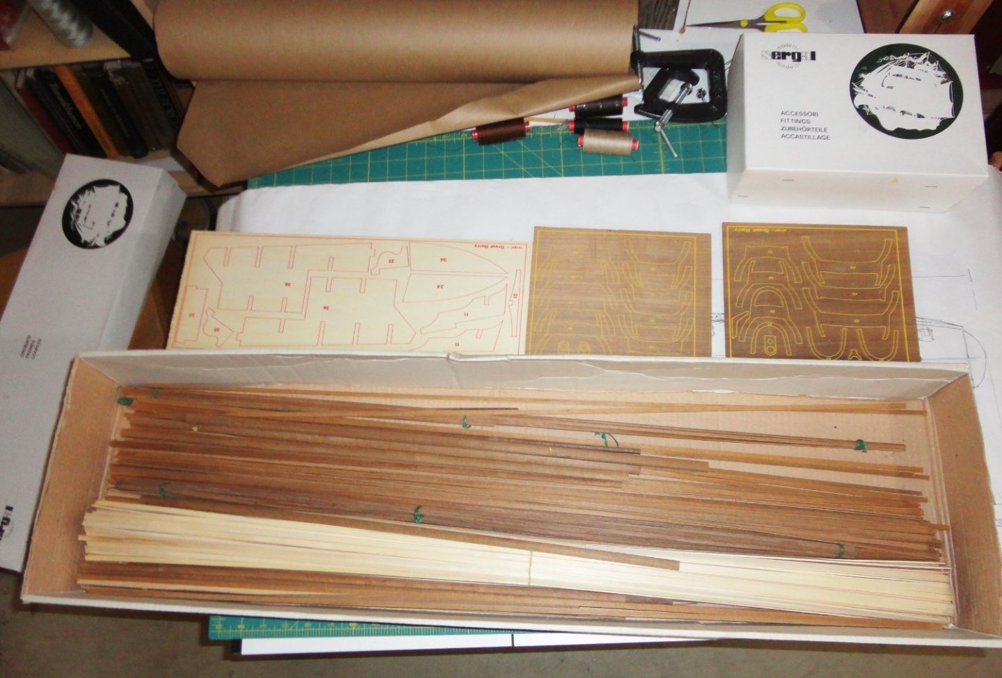
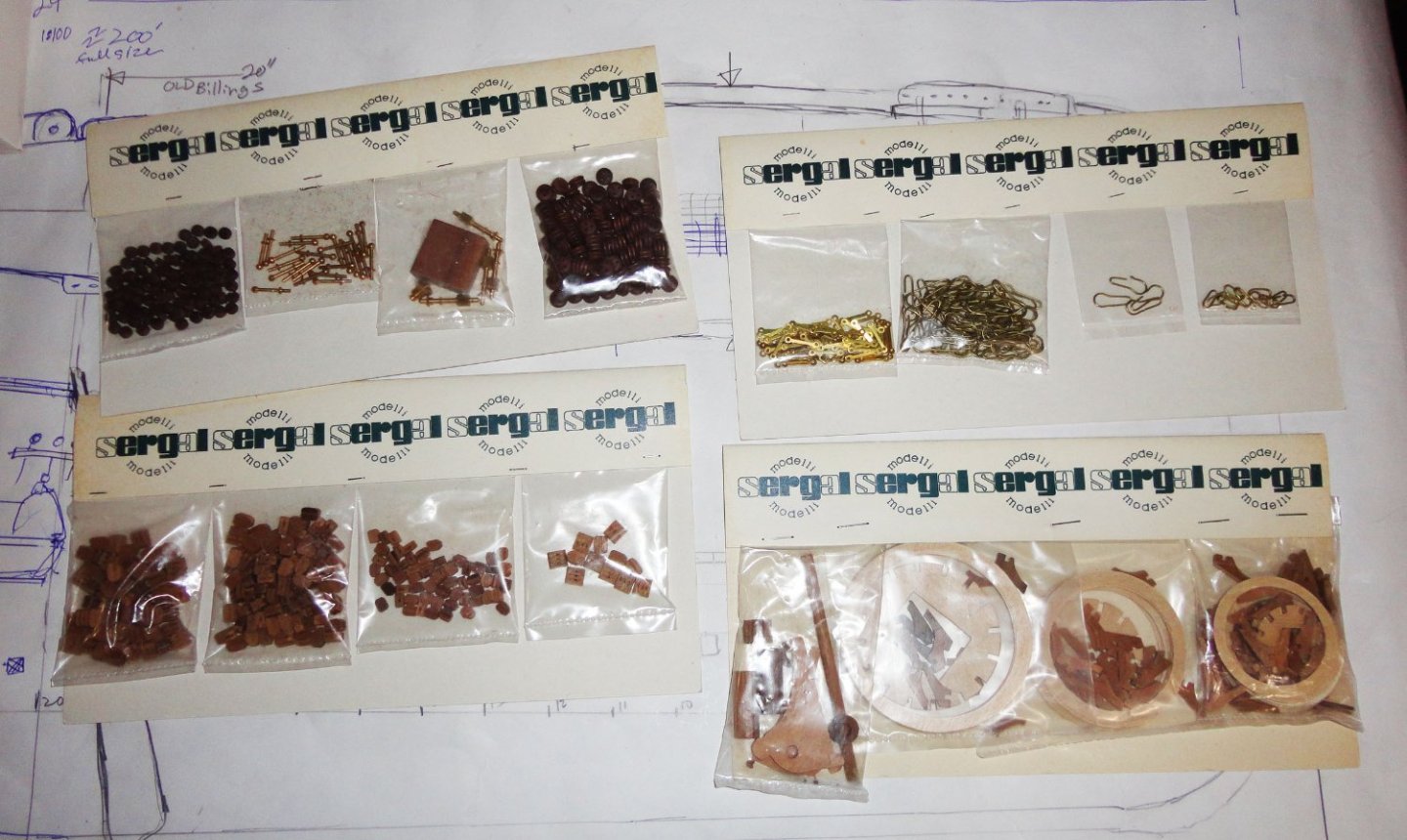
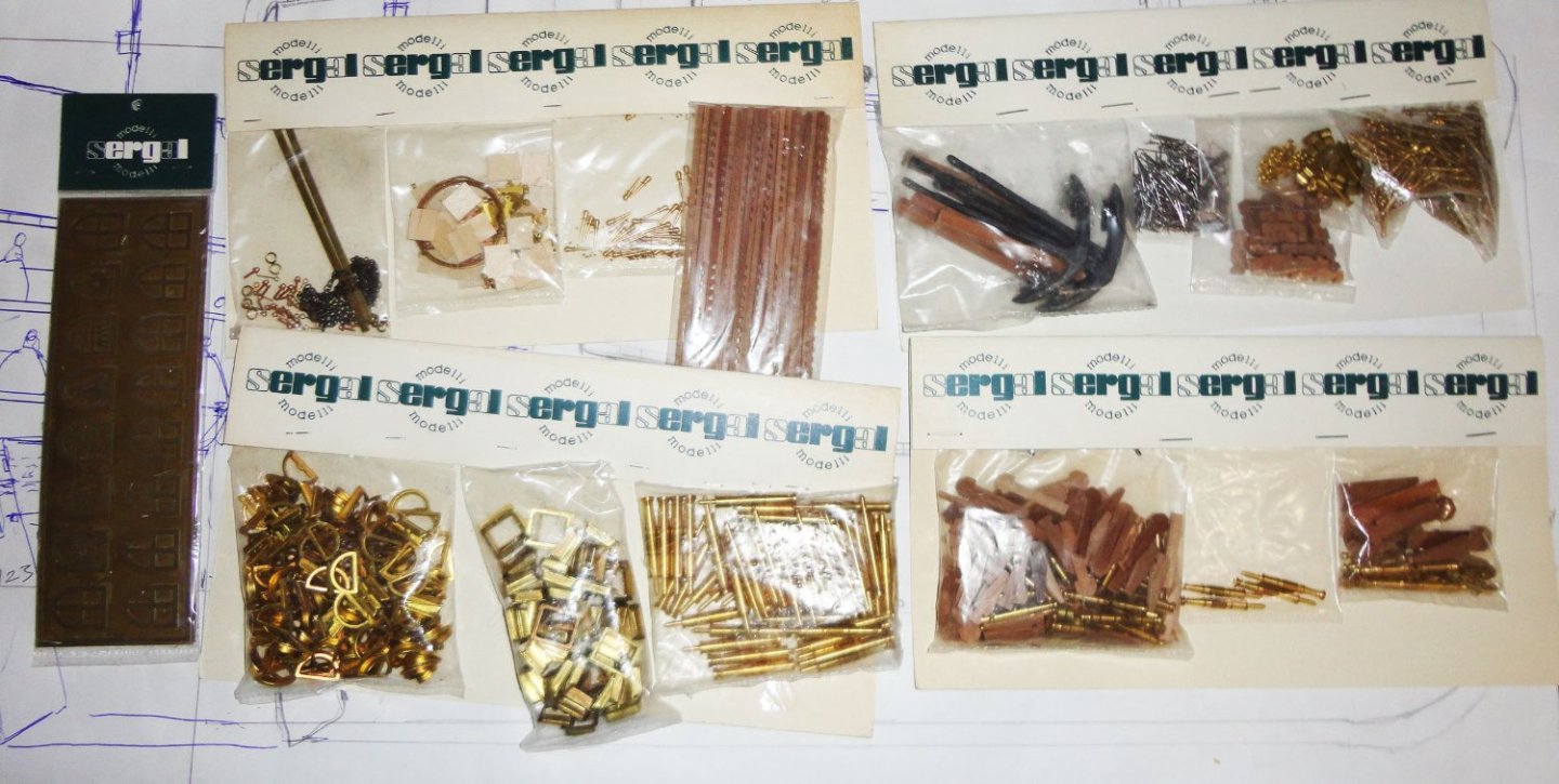
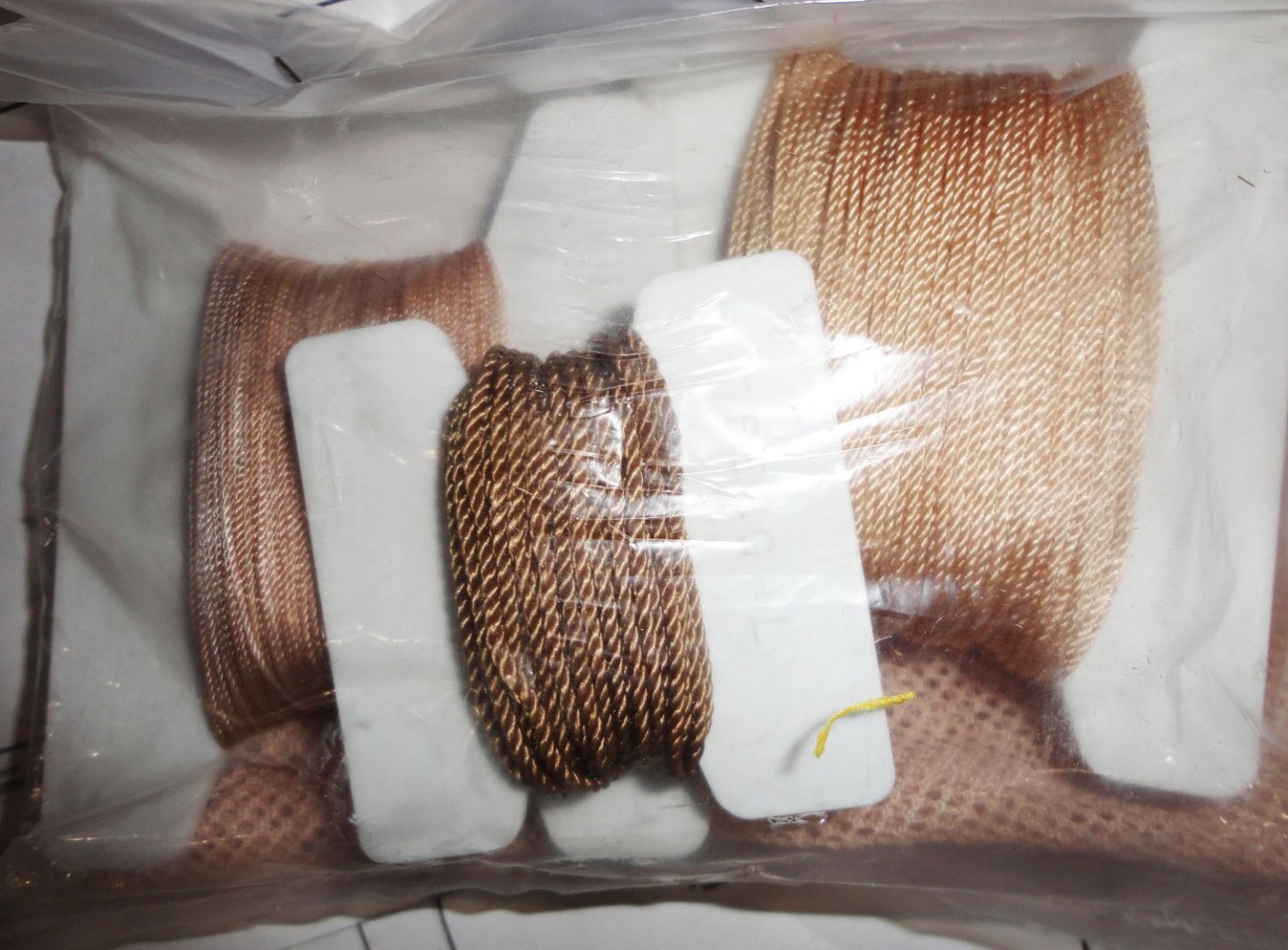
OK, let's dive into the box. 'Sorry for the glare where items are plastic wrapped - I don't want to tear anything open yet. When I do a build sometime, there will be better pictures. A blue plastic holder (with compartments) holds bronze castings that include a real nice dragon head for the prow, a grappling hook to hang from the bowsprit, a royal crown for the top of the bowsprit as shown on the Anthony Roll, rigging cutting knives for the fore and main course yard ends and a bunch of small decorations (perhaps for the castles). Very slight oxidation is present from nearly half a century of storage - nothing that won't clean-up. Below is the open box with a WHOLE BUNCH of planking stock, decking, mast and yard dowels (most stuff is walnut, but some is light) ... haven't yet bothered to delve into what passes for instructions. The mast & yards are not tapered (Billings old Wasa had pre-tapered stock) - but the forum has several threads on how to do that ... I'll use my Unimat lathe (lucky me). So here's some of whats in the framing box. All of this is cleanly cut with virtually no burrs and NO char marks (laser cutting wasn't done when this kit was produced). I'm REALLY impressed how everything in this box (which is most of the structural pieces) is done and numbered. You'll see later that there are three sheets of ply with printed parts that have to be cut out ... but they are for a castle configuration that I don't plan on using. Now there is a little warp on a few of these pieces ... nothing that I either can reverse-bend out, or at worst replicate. Most pieces are flat and true. Below I've spread stuff out in the box for a better view of the stock, the planking is thin enough to easily bend a fair amount without even wetting - and wetting would allow for tighter curve bending. The stock seems perfectly fine and not cracking ... care was likely taken in the orientation of the wood it was cut from. Now for the packs in the fittings box. First up are conventional chainplate - which is not like the simple chain used on the MR, but what is supplied will be useful on another build. There are very well made deadeyes - again not the tear-drop shaped, 7-holed period type (again from the MR) - they could be used as-is, but I prefer to make my own and use these elsewhere. They are really quite fine. There are single, double and triple blocks that are better than average ... must be that during this time period of production the Sergal fittings were a very good quality in general. The blocks may not be 'early', but I'm inclined to use them as supplied. And there is a group of 'kits' to make the nest-shaped tops - a nice touch that I really appreciate. The next group includes a bunch of swivel gun parts, a couple sizes of cannon kits (one of them contains sakers), 3/4 cannon (culverin) barrels designed to protrude through the side gun ports ... they fit into holes the builder drills into supports recessed behind the hull planking and that will have a nice appearance (no one would see the gun carriages anyway) as opposed to a contemporary kit-supplied method of popping inserts into square holes made into a the hull after it is planked. One can generally see the shallow back of these inserts even if they are painted black. I'll either use the recessed Sergal method or perhaps go to the trouble I did on the Vasa by placing 'dummy' carriages with the back part of the cannon barrel made of dowel drilled to accept the brass half-cannon (or in this case they are 3/4 barrels turned out of brass). There are a slew of gun port liners (which I won't use) as well as demi-lune liners which I'll probably use to 'pimp' the castles a bit. There are also a lot of other fittings and some grating strips. There are etched shields on the left that I don't plan on using. Last up is the rigging rope, which I must say surprises me how good it looks. It is miniature rope, and by far the best rigging rope I've ever seen in any kit from a large producer (note that I have not seen any of Chuck's kits, but know that they have his excellent miniature rope). The anti-boarding netting seen underneath the rigging rope is ... eh .. I suppose OK, but I don't plan on having any netting so you can SEE the decks and whats on them. Netting would likely only be deployed either during a drill (temporary) or before an engagement with hostiles. OK, old Johnny's nattered on in his typically convoluted way ... so how would he describe this vintage kit on one word? SWEET !

-
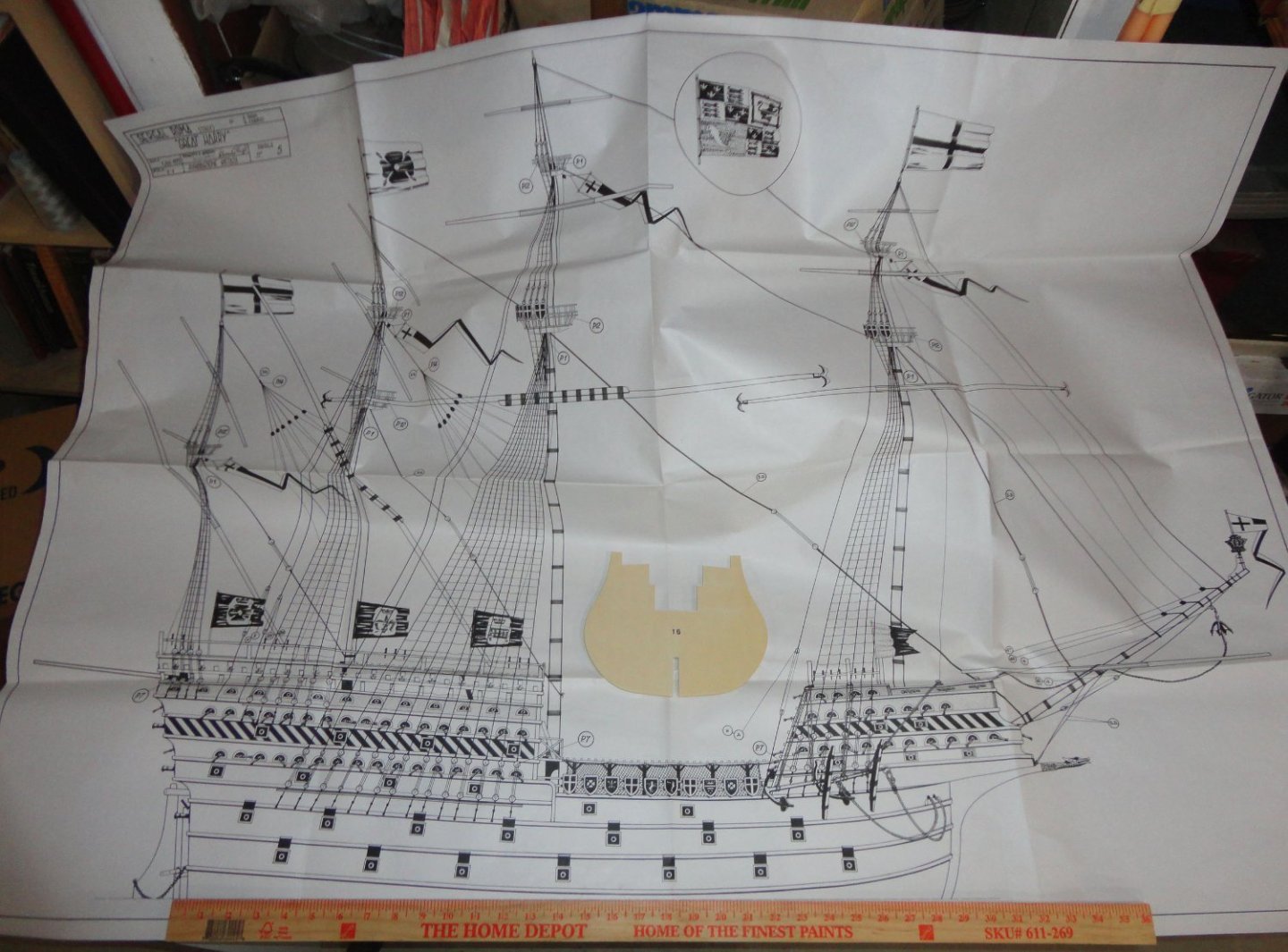
Yes, the model is large ... but perhaps not quite as large as it seems. The kit was made before the raising of the Mary Rose, and did not have the benefit of all the knowledge gained thereby in the decades of study to follow. So they had to have based the design on the few contemporary pictorial records available, plus their understanding of 18th & 19th century ship proportions. The ratio of length at the waterline to maximum beam of the MR is 3.25, so the GH should be about the same. Experts estimate the GH's beam at 50', which would yield about 162.5' at the waterline using the same 3.25 ratio. The widest frame (bulkhead) in the kit measures 7.75", so multiplying that by 3.25 should give a model waterline length of 25 1/4" Hmmmmm, the actual (full scale) drawing of the model has the waterline measuring 28 1/2" ... an 'Ah-ha' moment that provides a rationale to reduce the model length by 3 1/4". But then there are some slight alterations to make the bulkhead shape conform more closely to the MR, so the resultant adjusted width (with allowance for planking) will be 7 1/4 (or marginally more). Re-doing the ratio calculation will give a model length at the waterline of about 23 1/2 inches - taking 5" off the 'as designed' length of the model. The hull (less bowsprit) will end up being 30" instead of 35". This will make a difference in 'buildability' and management of the project - not to mention the size of the case eventually needed. The scale of the drawing (in length and height) to what is probable on the original ship is about 1:68, yet the scale "in width" of the bulkheads are 1:80. What about the guns included in the kit? (There are many !) I picked out a saker barrel (originals are about 9.5' long) and measured it through the plastic bag and got 1 3/8" ... (x 85 represents 9.7') pretty close to being in proportion to the model's beam. The biggest cannons (11' originals) and culverins are 3/4 length turned brass to be mounted into recesses behind the gun ports below deck (a common practice with models), so my reckoning of the full length (if they were fully turned) is about 1 5/16" (x 85 represents 11.1') ... so the gun are about 1:85 scale, still al little smaller than the proportions of the bulkheads. Most of the drawings are the elevations only, but where drawn, the view of the decks from above look somewhat 'stretched out'. So we have a situation just the opposite of the old (1st edition) Billings Wasa (Vasa) where the scale length of the hull should have been 24" but was reduced by 4" to fit the box they were using for all their models then. Sergal (in 1975, the date on the drawing) sized the length of the model in their best guess of how the proportion should be to the largest bulkhead size they chose (not knowing then what we know now, I don't blame them a bit). They chose not to be limited to any size box and 'went for it' as one might say now. So based on current scholarship, parts can be adjusted or re-made as needed to adjust the length and height downwards a little. There is no way of 'stretching' my Vasa now (but it could have been done at the outset if sufficient information was readily available in the 70s ... (isn't the internet a trove of info?), but with a little planning there should be no major difficulty in trimming the Sergal Great Harry to a length proportional to its beam for Henry VIII's big ships. So lets look at a few more plans (they are VERY large and I don't intend to post pictures of them all) ... they just don't print plans like THESE anymore ! The plans are the primary 'instructions' for the build, supplemented by ten 6" x 8" pages of typed material (in Italian, French and English), that mostly tell you to refer to the drawings for each step. Obviously this is not a 'beginner's' project, given the scope of the work, the modifications that should be made to the 'as supplied' configuration, and the reliance on the drawings (nice as they are) as the only effective means of instruction (other than just a few pointers in the booklet - to be picture further down). Prior ship modeling experience is recommended, unless one want a 'baptism of fire'. The drawing below (and on others) indicates belaying pins (supplied, of turned brass) - which had not been invented yet. I'm not sure about kevels, but there were knight heads and railings of various sorts. On the drawing below, one can note the exaggerated tumblehome in the central area of the frame layout on the left, and on parts of of the framing in the upper right. How to adjust these and also how to make a better construction of both castles will take some study and experimentation. I anticipate making a number of replacement framing parts and trial-fitting everything multiple times. One still can simply 'build as supplied' and get an impressive - and large - display piece, bristling with about 180 guns of various sized. If its 'Guns R US' one is looking for, you've come to the right place. There is a cool wall poster over 2' x 3' which is pictured next, and the brief 'instruction booklet' is at the lower right corner for comparison.


-
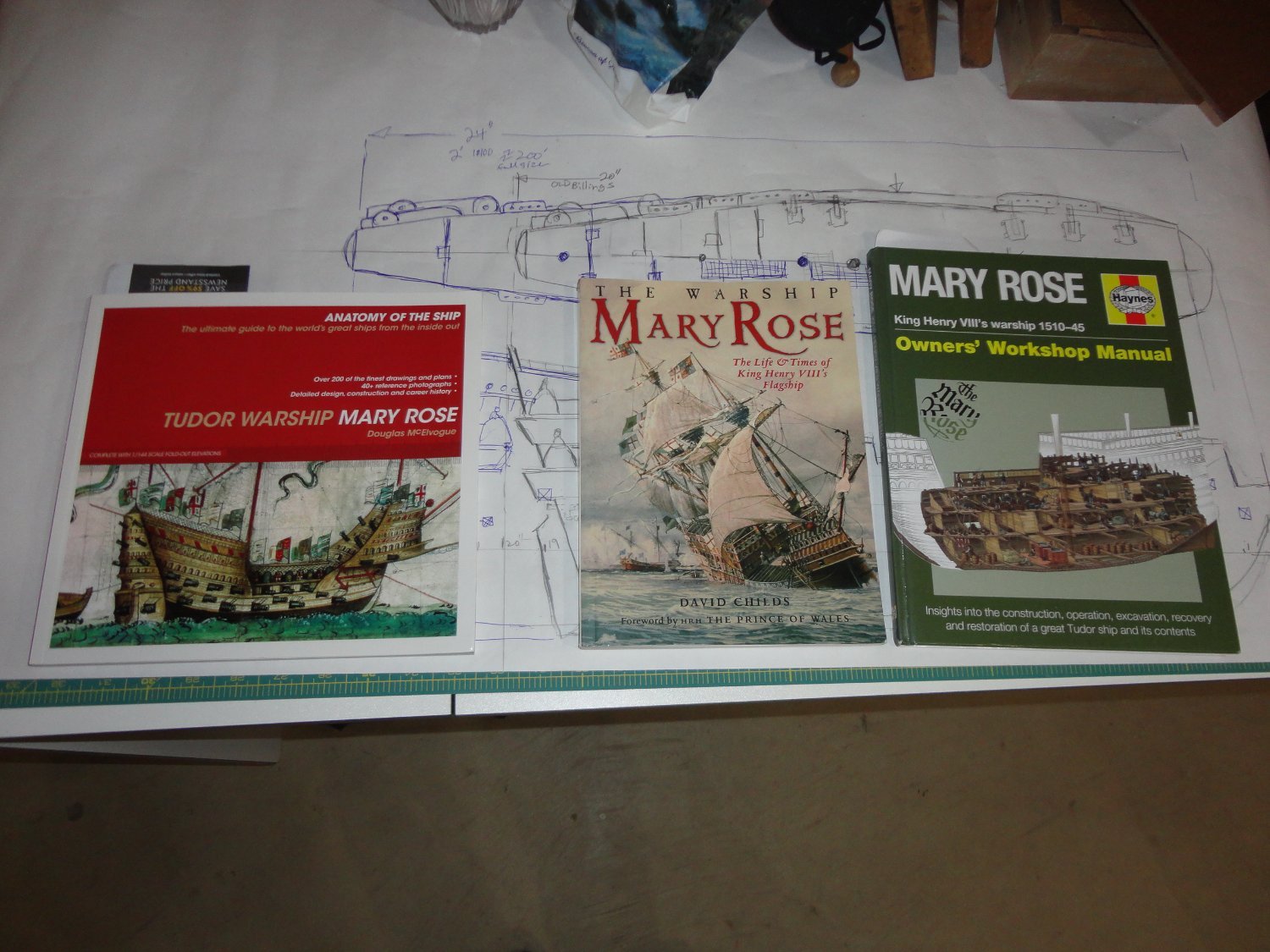
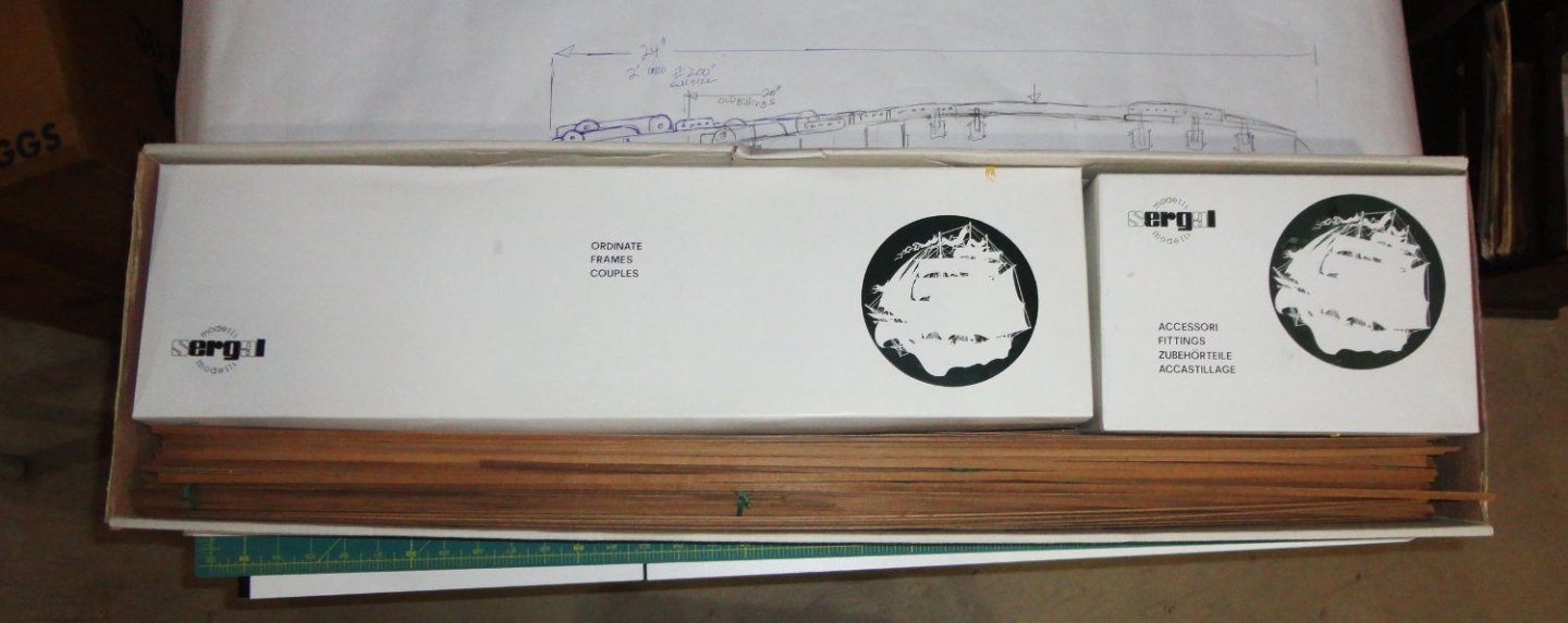
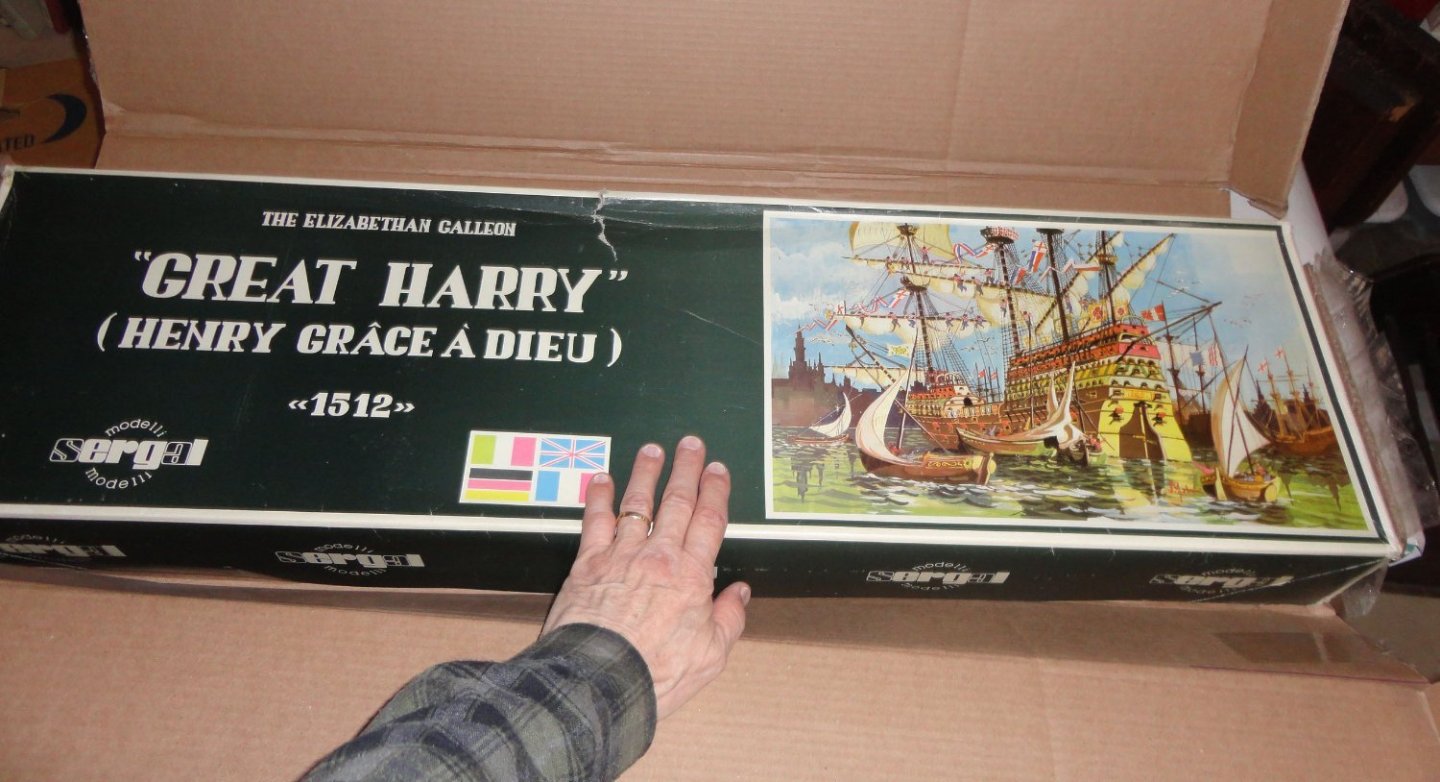
Ahoy from Snug Harbor Johnny ! This is my third unbuilt kit review (reference Endurance by OcCre and Khufu's Solar Barge by Woody Joe) and this will take a few posts to do this fine old kit justice. Like the man asked, "How do you eat an elephant? ... One bite at a time !" As mentioned in the 'What did you Receive Today' category, I was informed about the availability of the the LARGE scale Great Henry by Rick from the Modeller's Workshop in Montreal, Quebec. BTW, he was a pleasure to deal with and the parcel was received much faster than I'd have guessed. We were discussing a completely different old kit he offered to the Forum, when he mentioned that there was a group of 4 kits that were dropped off at his store for consignment that included the HMS Victory and the USS Constitution. There are many fine builds of these, as well as the Bounty, but the prospect of a BIG version of the Great Harry piqued my interest as I've only seen a couple of pictures of this version anywhere. Rick noted that it is unlikely that Sergal produced more than 100 of these, with drawings dated January 1, 1975 - well before the Mary Rose was raised (much less conserved and studied enough that quality reference books became available). He posted some pictures of kit components without 'digging' too much into what he described as entering Tut's tomb, and he suggested a price including shipping of $500 ... yet went so far as to say I was welcome to bid lower if I was interested (as this item was considered a 'slow mover') and he'd relay that offer to the consigner. No way was I going to risk offending anyone, and I was willing to 'pay to play' and agreed to the initial price suggestion. I don't risk giving too much away by saying that I think it was fair value given the unusual nature of the kit, and to do it justice will take a real commitment of time and effort. As mentioned in the other thread, the box weight 15 pounds and I was surprised by the mass - as if there were bricks inside the carton. 'Turns out that the large box was fully packed with materials (wood, metal and paper) - enough to be considered a 'solid' mass. The picture below is of the first opening. Sergal had to design this based solely on a few contemporary illustrations, and their experience with 17th through 19th century ship kits of various types. Prior to receiving the parcel, I'd procured three great reference books on the Mary Rose (pictured below) because Sergal had 'gallionized' the Great Harry somewhat as exhibited by putting too much tumblehome in the widest places than we know is appropriate based on the recovered hull of the Mary Rose. The Great Harry, after all, is a larger and better armed version of the MR - and was built to match (or exceed) the newly built Scottish warship the Great Michael. These might be thought of as 'Carracks on steroids' - taking the recent carvel-below, lapstrake above construction developed in the late 1400s (reference the Danish ship Griffin - Griebshund - now located and featured on a PBS NOVA documentary) and expanding the size with 'less tubby' lines and more powerful weaponry, 4 masts and the new innovation of sealable gun ports in the sides so the heavier ordnance could be lower in the ship for reasons of better stability. Sergal had three full decks in the stern castle (although the top is narrower, what, so it looks a little more like a galleon? ... and its DEFINITELY not "Elizabethan", even thought Elizabeth I was a Tudor Queen). They've played a bit with the forecastle as well, but then I'm not 'knocking' the manufacturer at all - considering the date of production and the paucity of accurate scholarship in the 70s concerning Henry VIII's fleet. In fact, the re-build of the GH in 1536 (the MR was also rebuilt, but loaded with more and heavier guns that likely played a key role in her demise - but much to our present scholarship, so look on the bright side) the sterncastle of the Harry was reduced to lessen the heeling it was previously noted for. So the original version should have 3 full decks in the stern castle, and reportedly did not have top gallants in the pre 1536 version. My intent (when work will be done on the GH) will be to incorporate information in the book pictured below to build a pre-1536 version: OK, time to have a look at the first drawing that lay on top when the kit box was opened. Yup, this model is BIG - and the length at the waterline is 28 1/2", and the hull from the beak of the fore castle to the stern (not including the bowsprit) is 35". And talk about height ... if taken at face value, it will take a larger case indeed. Baggins might consider this a 'mathom' - or perhaps some might think a 'white elephant'. Bur wait - a 1:75 Vasa or Cutty Sark will be as large, and there are many who build models this size. I've been struggling with 1:96 and smaller for a while, and having more 'elbow room' might be a good thing. So in the picture below I placed a yardstick for scale - and also the largest hull frame that points to a rationale how this model may really be 'not as large as it seems'.

- 32 replies
-
- 12
-
-
You are fortunate to have those nice bronze castings ... a reason for someone with enough of a nest-egg to find and buy the Classic kit PLUS the new version with improvements in drawings/ templates, etc. Then they can have the best of both worlds, besides having plenty of material should anything go wrong along the way. Nice as the bronze castings are, they can be improved by working with tiny Dremel bits and miniature files to accentuate fine detail and make them 'super cleaned-up'. I could see spending the better part of a year just going over all the castings this way. THEN after buffing, one could have them professionally GOLD plated ! For that process there are several cleaning/chemical treating steps, then the substrate is nickel plated for longevity and to sequester the gold to be plated on the surface. The final step is to electroplate with gold, which will burnish to an unmatched brilliance that will STAY brilliant for a very long time ... like the golden mask of King Tut !! Yeah, it would cost to have all that done, but I think it would be worth it.
-
"I tawt I taw a puddie-tat ..." (Tweety Bird in the old Warner Brothers cartoon) Then there was Yosemite Sam, "Great horny-toadies!"
-
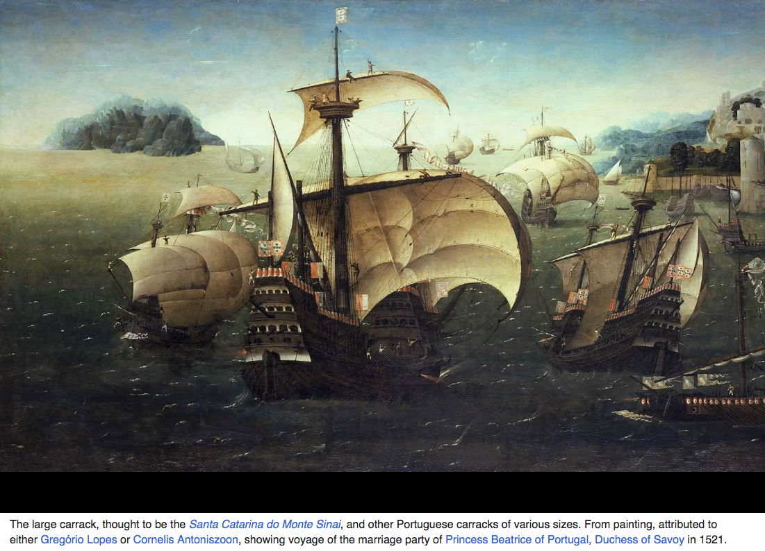
Ahoy Steven, sorry for the delay in reply - as I often miss activity. The 'marriage' painting I referred to might be in your collection of images somewhere. I'm pasting it below: Cool picture, eh? Brave crewmen are walking the yards (but seem to have one hand on a line), and there is great detail in certain aspects of the rigging and how the sails actually looked under a breeze. I note on the large ships in the foreground that they have three decks on both castles, with the top deck on each not going the full length of the one underneath.
- 740 replies
-
- 6
-
-
- Tudor
- restoration
- (and 4 more)
-
sagging standing rigging
Snug Harbor Johnny replied to Dziadeczek's topic in Masting, rigging and sails
Ah-ha ... I'd forgot about the heat-treat step Chuck uses. That is, wind the poly mini-rope around a metal pulley and put in a toaster (or other) over at 350 degrees F for no longer than 5 minutes - then allow to cool on a rack. I will try that. As for linen, many 'old time' ship modelers used a generic type of fly fishing line known as "Old Cuttyhunk", which was mass produced (many different labels and brands, ergo they're now in collections) through the 1940s and available for quite some time afterwards from stock. It's a collector's item now and very expensive, and the thinnest version (something like .015" diameter) is the rarest. It was often white, so for standing rigging it would have been dyed. I've seen some here and there in antique shops still on a reel (for a rod and reel) as a collector's item ... and very $$$. But I handled some of the line, and indeed it was true miniature rope that was very flexible ... as it had to be for fly fishing. I think my old friend used to fish with it back in the day. -
'Just imagining ... based on the classic movie with Bogey and Hepburn when the Queen went out to torpedo the Louisa. Some choose to model 'imaginary' ships - like Captain Jack's Black Pearl (as seen in the movie), the H.M.S. Surprise as seen in Master and Commander, the first Disney Nemo's Nautilus - complete with giant squid, and even (on this forum) a cartoon Asterix boat heading for a Viking ship. It's all up to the whim of the builder. Now I knew a man years ago who built an 18" long version of the African Queen with a working mini steam engine (it was 'lake worthy') as well as a working model sailboat with a 'vertical multi-blade' windmill for propulsion. His name - Richard Derby Elwell - who was on the U.S. fencing team in the 20's that competed in the olympics, a self-employed designer of warehouses and serious fly fisherman who would not hit the streams of Long Island until well into the season when the 'easy fish' were gone and the ranks of fishermen had thinned. Outfitted by Abercromby and Fitch in NYC, he was a rare example of an accomplished gentleman and connoisseur. I was a boarder at his residence in the 70s for one of two semesters of paid internship for the Navy at Grumman Aerospace and worked on the F14, among other projects (they PAID qualified interns in those days, whereas today young hopefuls are free labor 'for the experience'). Perhaps I was just remembering that grand old man, and regretting not availing myself of his mentorship more than I did.
-
This is a great model. 'Wonder if anyone ever did the Koenigen Louisa and the African Queen as a pair?
-
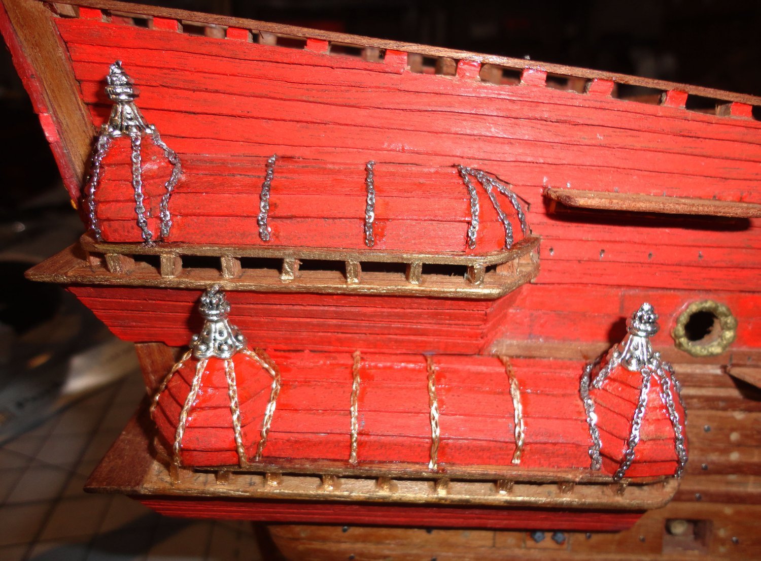
Hey Gustav ... want me to 'pimp your ride'? I've long been pondering what to do with the gallery and cupola roofs on the Vasa, since the original has a lot of curved carved sirens (or other figures) mounted for decoration. They are very skinny but still painted. Kits today (1:75 and 1:65) have moulded figures that go all over the model, but the 1:100 old version I've been fooling around never had any. You've seen the military miniatures (HO, N and I've found a few Z for good measure) that have been modified and painted to be 'good enough' for my purposes - as well as the moulded stern piece (from plastic wood formed by a latex mold I made over a plasticine original) that painted up pretty well. Yet the irregularities in my built-up clinker (lapstrake) roofs preclude the application of uniformly molded bits. Rather than leave the roofs plain or try and just paint decoration in, I tried using fine chain - first 'flattening' the chain a bit by using a planishing (flat faced) hammer and a flat steel base. Still, the chain was fiddly to work with (a pain , actually) - and after dong some, I thought of another approach. I braided three pieces of 26 gauge soft beadwork wire from the Admiral's horde (with permission). The starting end was twisted a bit and put in the edge of a vise, so that the 3 strands were tugged into an ordinary flat braid (like braiding hair). Before trimming anywhere, a small amount of regular CA was dabbed on the location (where it 'wicked' into the braided structure) and touched with a little accelerator for a quick cure. The braided strand can be bent as desired and is MUCH easier to work with than the chain. The top end of a section to be applied was pinned into place and a potion of the run was tacked with CA (and accelerator). A dental tool was used to control the amount of glue applied (sort of, since thin CA tends to want to 'run' everywhere), and a dabber applied the accelerator. The next bit of run was then positioned, then glued. The place to cut was glued first (to prevent individual wires from shifting at the cutting point), and the cut end was pushed into place and glued. See photo below. 'Looks 'good enough' for me - so I'll do the other side with braided wire before attaching any painted figures. Now it was so much trouble getting the chain in place that there's NFW I'm even going to think about pulling it off to re-do. I expect that before long there will be a development concerning perhaps the 'next' build I do once the Vasa is done as far as I want to go. But I'll wait until the chicks have hatched before any crowing. It will mean either putting off a clipper build - or perhaps dong one concurrently. That can be a way of doing things on one build while glue cures (or whatever) on the other. That would mean a longer time to the completion of both, but not as long as the time to do each sequentially. Hmmmmm, we'll see. Fair sailing! Johnny