Snug Harbor Johnny
-
Posts
1,501 -
Joined
-
Last visited
Content Type
Profiles
Forums
Gallery
Events
Everything posted by Snug Harbor Johnny
-
 Those bronze rams could really punch a hole in an enemy ship's hull ... enough to ruin that captain's day.
- 536 replies
-
- 4
-

-

-
- Quadrireme
- radio
- (and 1 more)
-
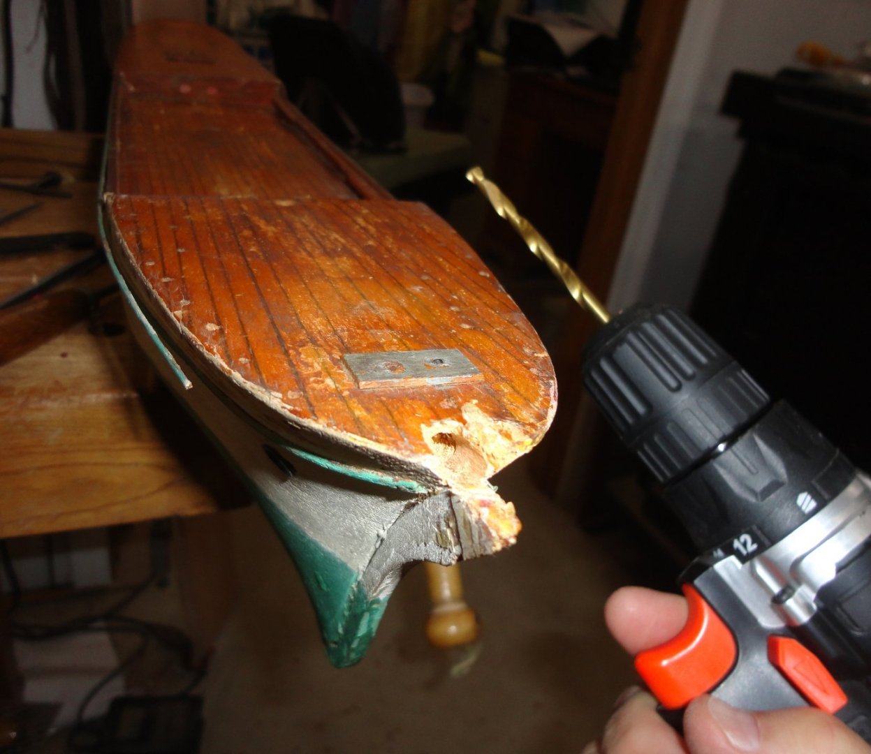
While drilling for the bowsprit, a couple problems arose that were resolved sequentially 'on the fly' without even thinking to document them. Needing both hands for a lot of stuff, certain things just don't get photographed. It wasn't just a matter of drilling away, even after squaring the surface with a fine saw. The drill bit needed kept wandering without biting - so I thought a much smaller pilot would worth trying. The pilot did grab, but soon wandered off-center - so that hole would be worthless since a larger drill will follow a smaller pre-drilled hole. What I should have tried was to use a prick punch (or use a nail) to provide a center before drilling the pilot. So a small 'U' gouge for wood carving was used to incise around the desired periphery (ignoring the errant beginning of the pilot hole) so it could be dug out in bits. Being end grain, the excavation had to be done a little at a time to make a right-sized hole for the full-sized bit that was about 1/8" deep. Then the larger bit drilled with light pressure and stayed on course - reaming out the remains of the original bowsprit still in the hull. There is a little room for adjustment with the new bowsprit installed, so it will have to be positioned carefully while the epoxy sets (when that time comes). Of course, the hole could have drilled poorly, in which case the remedy would be to turn a suitable plug of wood to glue in with wood glue ... then a second go could be attempted. This is a nice aspect of modeling in wood. I found a quote from Marcus Aurelius that applies to our hobby (and also life): “While it’s true that someone can impede our actions, they can’t impede our intentions and our attitudes, which have the power of being conditional and adaptable. For the mind adapts and converts any obstacle to its action into a means of achieving it. That which is an impediment to action is turned to advance action. The obstacle on the path becomes the way.”
-
The restoration has indeed captured my imagination at present, and the plan is to proceed - albeit in steps - to completion before going back to the Vasa (the build title has the old Billings Wasa spelling, and that project is being 'busted' enough to get a 'reasonable facsimile' - no great 'accuracy' is possible due to the limitations of the earliest kit). There is definitely a charm to the GF model, and I want to strike the right balance between some modest improvements and respecting the configuration as-built. Once all the groundwork is done, actually finally getting some experience on rigging enhancements ('though with simplifications) should be a treat.
-
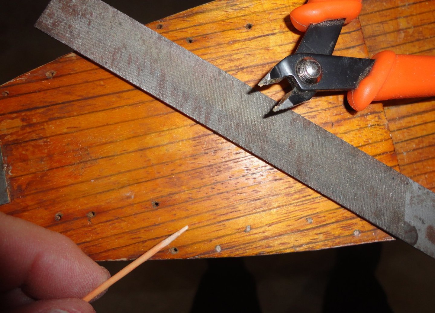
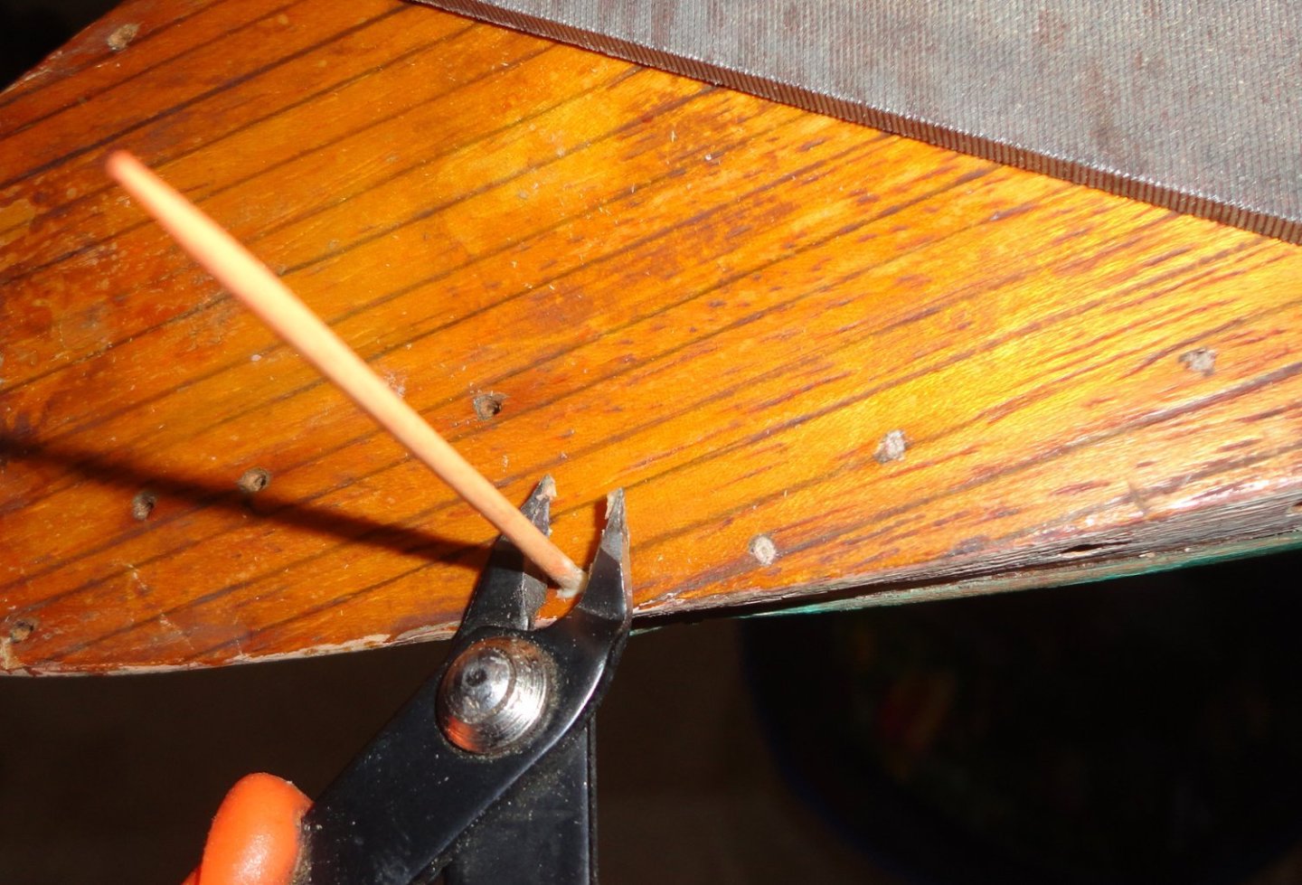
The nail holes are being filled ... I trim off the end of a toothpick and file to make it more cylindrical (like the holes - which may have been drilled first just a little smaller than the nails used fore the stanchions), then trial fit before dipping the end in titebond and filling the hole. Step 2 is to flush cut. Step 3 is to tap lightly with a planishing hammer, and just a tap with the nub on a grommet set if needed. I'll touch up the color with shellac, which will also penetrate the end grain of the toothpicks. The builder's hole pattern (such as they are) will be followed so as not to make any more holes in the deck as necessary.
-
For what its worth, the Austrian Unimat SL from my Dad (he really never used it) has been handy turning and boring small, occasional work in brass and aluminum, but the main drawback is that it is underpowered for steel - unless the diameter is small and very light cuts are made. Changing over to the milling arrangement seemed too much effort. (I have done milling odds and ends on my drill press with a stand equipped with a cross vise.) The four jaw Unimat chuck was used for odd sizes, but centering was always a pain - so stock had to be trued. Once I got hold of a used 3-jaw universal chuck, centering was automatic for round stock ... small diameter stock passed through the head entirely. If I was going to be doing a lot more metal work (which I'm not) I'd look for something a little more substantial with the power to do steel with decent cuts.
-
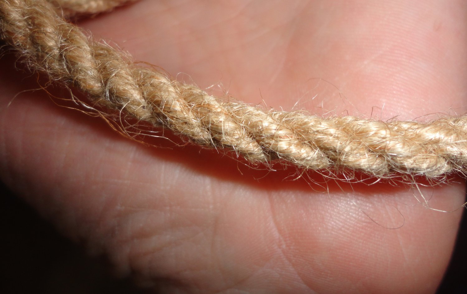
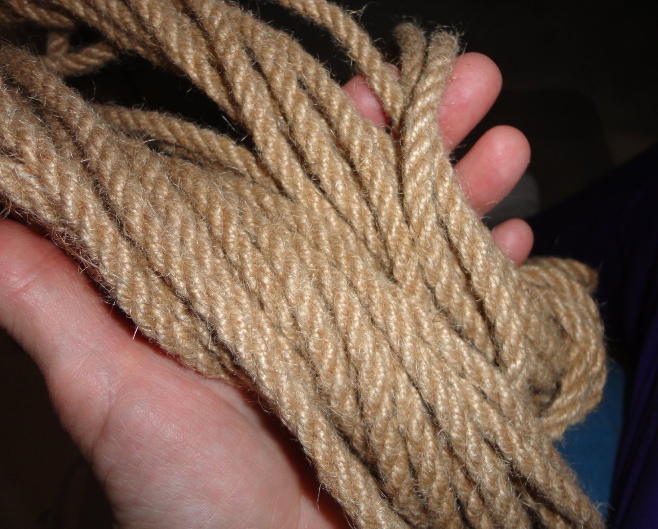
I've made aprox. 3/8" diameter rope for demos ... this size seems to happen 'naturally' by using twine of either sisal, jute or hemp. Sisal is the worst for little 'bits' sticking out, jute approximates hemp - but hemp (the best) is also expensive. Three lengths of twine are strung on each of the three turning hooks for ordinary rope, and the counter twist is regulated by the rope maker's 'top' ... or by reverse cranking in other setups. As you can see in the photos, from a foot away (the first picture), the jute rope seems minimally fuzzy. But get in to a couple of inches away (the second photo) and it DOES appear as fuzzy as your rope. From 6 feet away (72"), you don't see anything ... and at 1:72 scale that would be merely an inch away from scale rope. Ergo, 'average' kit rope that looks fuzzy from an inch away should not be used ... nicely made scale rope passes the 'inch away' rule. BTW, I found that using a little bees wax on the twine reduced the 'fuzziness' of 3/8" rope by about half.

-
If hooks are made of metal (whether wire of P/E), the eye should be able to twist 90 degrees with 2 pairs of pliers (and deft hands) once without breakage. Don't over-bend or bend more than once in order to avoid work hardening of the metal. If the eyes are plastic, then there may be a way to warm them sufficiently (without melting) to allow for a similar 90 degree of the small eye ... once cool, the shape should be stable.
-
As is often the case, you get what you pay for - so if seems 'too good to be true', it isn't. In a pinch, I bought a low-cost mini table saw from Harbor Freight that had some issues. For one thing, it only came with a coarse blade - not of much use for us - so I had to look for mini blades having a 1/2" arbor hole. This took some looking, and a set of three different blades was found on line to get the one fine-toothed blade needed. The height adjustment of the blade above the table is crude, but that's not too much of an issue. But there is NO fence - a distinct disadvantage. I ended up clamping wood the the table top to act as a fence. The base of the unit is on the small size, and not nearly as stable as preferable. So something like a Byrnes is obviously a much better thing to have ... perhaps Ebay might be a place to look for a used one. At one time I was into re-conditioning U.S. Civil War era arms (lower grades, known as 'shooters' - vs stuff to collect), and a man ran a shop on his property where he made a wide variety of bullet molds for antique guns (Rapine bullet mold company), as well as loading dies and other stuff useful for antique weapons. Time passed, and he retired. Since no one bought the business, it just 'went away'.
-
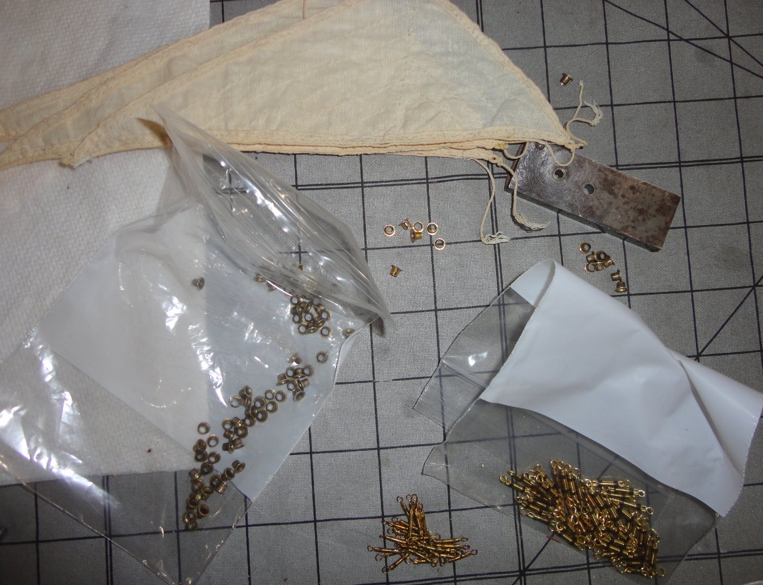
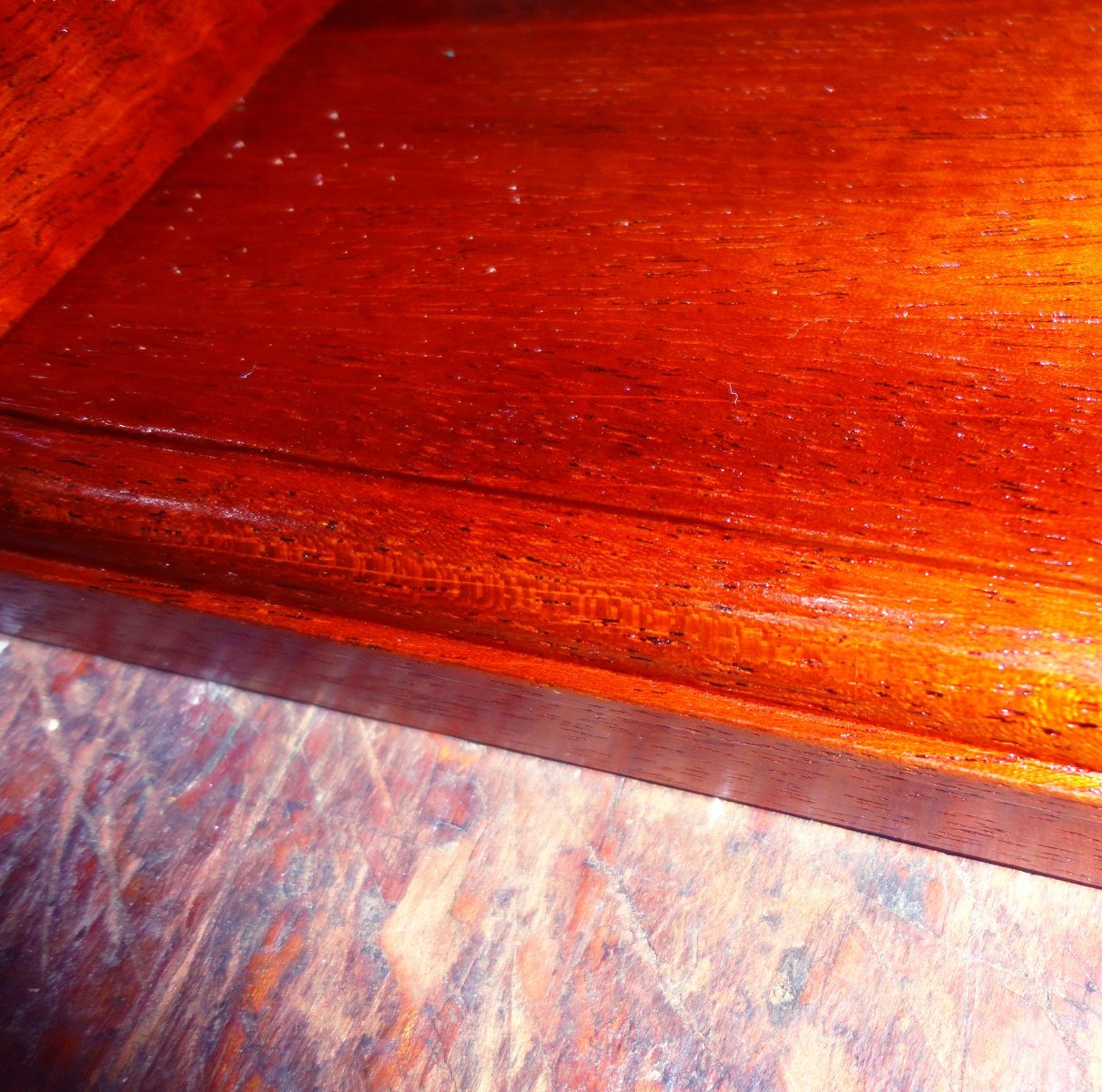
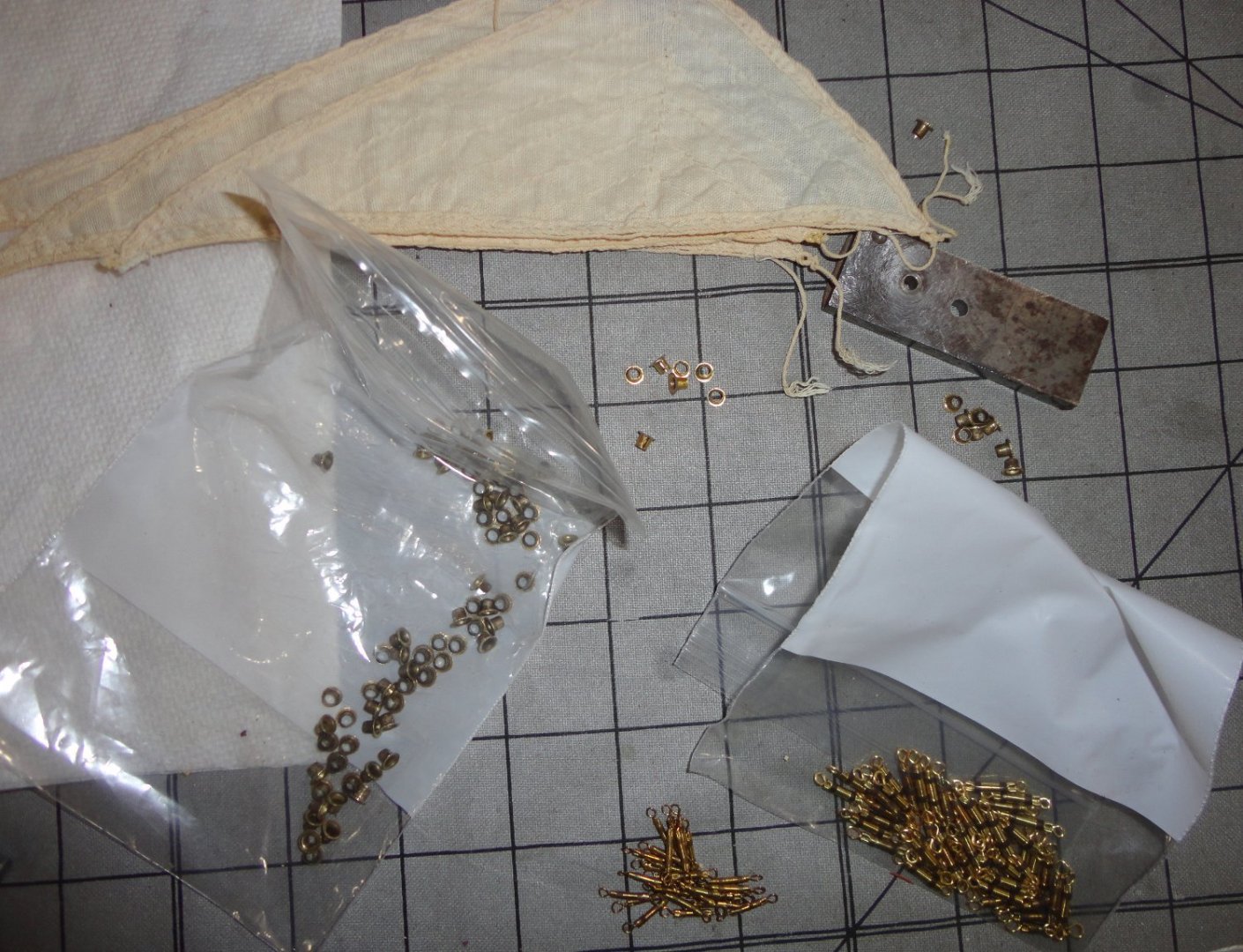
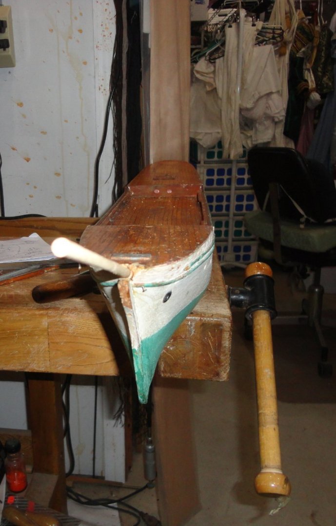
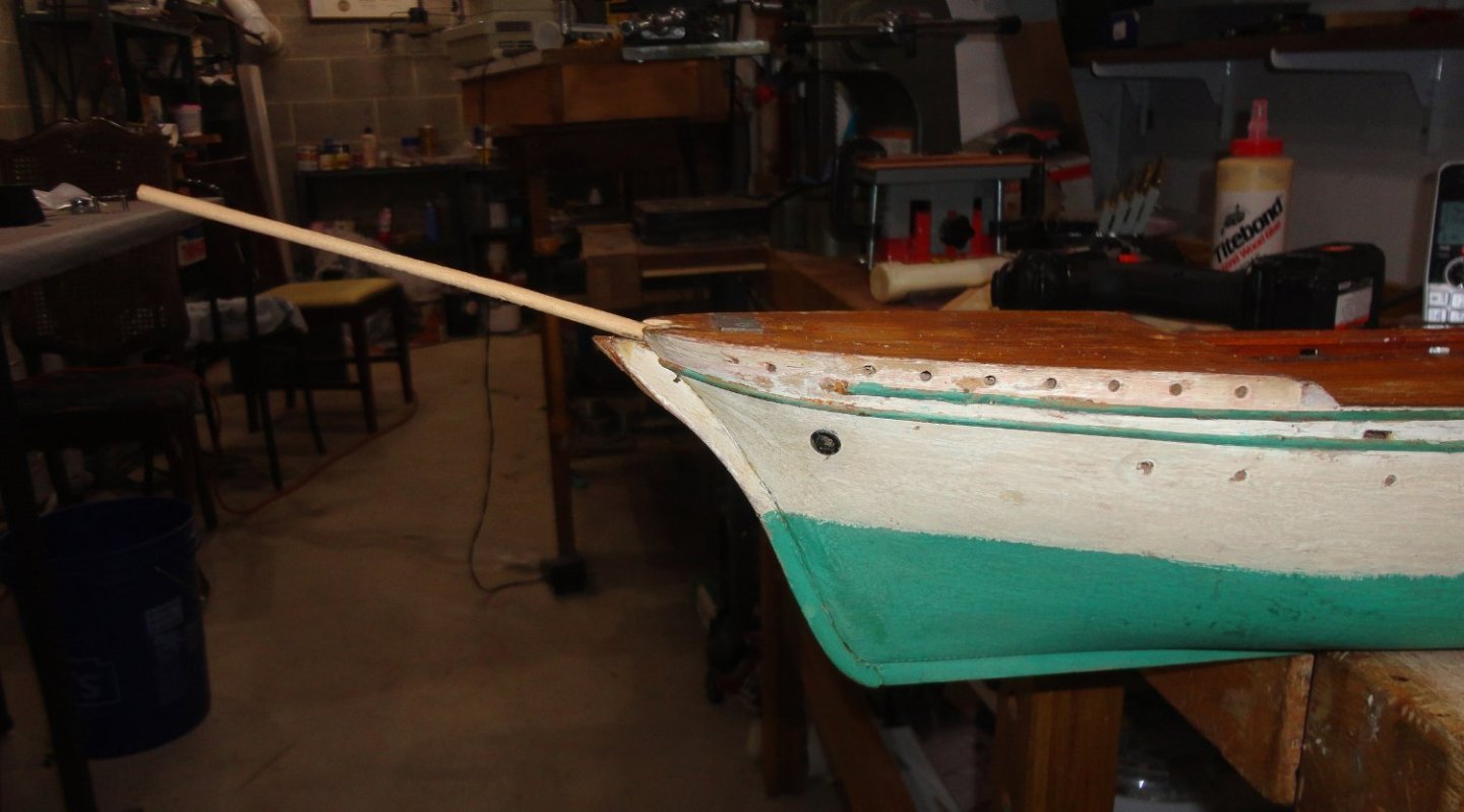
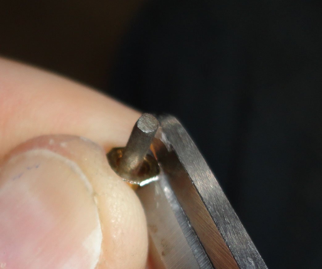
Such a glorious weekend for October in SE Pennsylvania ... and no 'first frost' yet, so all the annuals are still in excellent bloom. Yet it is not to last, so there may be better restoration progress once the cold sets in (at last). I ended up 'spinning' the original eyelets to get rid of any ovalness, and also to reduce the flange a little. Now I'm really happy with them. The lick of the grinding wheel did produce micro burrs, so each was de-burred and planished again to restore flatness ... all 82 of them (not counting 6 spares - 2 of which are already needed). What I seem to be doing is 'kitting' this project as each small bit is decided on and then accomplished. There's a box with the purchased items, and the scratch or reworked items are going into plastic bags. There are sail sets, cleaned masting, 2 sizes of turnbuckles - and the concept drawing for the rigging (yet to be finalized). Doing my own 'kit' is comforting, as I've always liked kits - whether built 'out of the box' or modified however much. NOW was the time to grit my teeth and decide what to do with the bowsprit. The concept of joining the original with a rod just won't provide the stability needed once rigging proceeds. So a tapered piece of masting (some top mast) from a parts kit was found, then the last inch had the taper removed on the lathe so it will fit properly into a cylindrical hole to be drilled. How to do that ... An ordinary bit was selected since the end of the bowsprit is a non-standard size, so I knew 'grabbing' and keeping the angle right would be tricky. There was some tearing at the mouth of the bore, but ... there are always some unplanned things that happen. You can see the 'sprung' trim on teh side, but that will be glued with a little pinning for good measure. The nail holes (previous uprights for the railing) will be filled with tooth pick and re-drilled for the nice brass stanchions purchased. Before the bowsprit gets epoxied, it will have to have all the hardware mounted and be painted white. Finishing the hull will also be done before mounting the bowsprit, since one done - it is a vulnerable part, and many models (like this one did before) are subject to accidental breakage. Bur just to prove that my eye wasn't off, the stem was test fitted and it looks OK. There is work to be done in the bow area as well. The above step, being accomplished, has me breathing a sigh of relief. The first coat of shellac was given a day to dry before light sanding and re-application. Two more times it was sanded and re-coated. Shellac is 'funny', in that the rough surface of the wood (if seen highly magnified) presents mountains and valleys ... and the shellac coats all evenly (with some absorption the first go-'round) - leaving the same profile. Sanding 'knocks off' the mountain tops, but leaves the valleys slightly filled in. Subsequent coats also tend to coat evenly ... don't even think of 'over applying' to try and "drown" or bulk fill-in those valleys, since that will make a gummy mess. With each sanding, more of the 'mountain tops' get leveled off as the valleys do finally fill-in. When taken to a planar surface, then building up a thicker flat coat, some wadding inside a twisted piece of lint-free cloth is the applicator to keep everything smooth and even - with the final pass or two done with just a little alcohol alone. This is what is known as a 'French Polish' - like on fine colonial furniture. There is still some natural thickness variation that gives it a finesse - not the thick 'plasticky' look of urethane. And some woods (like mahogany) have a 'shimmer' known as caytoyency - an almost 'jewel-like' appearance. I only go to this amount of trouble on fine furniture. For the stand, I chose to leave some of the grain in evidence ... a little like the best of both worlds. The color is a little off in the picture, and there are some flash reflections in dots or streaks. The wood looks far better 'in person'. So far, so good.

-
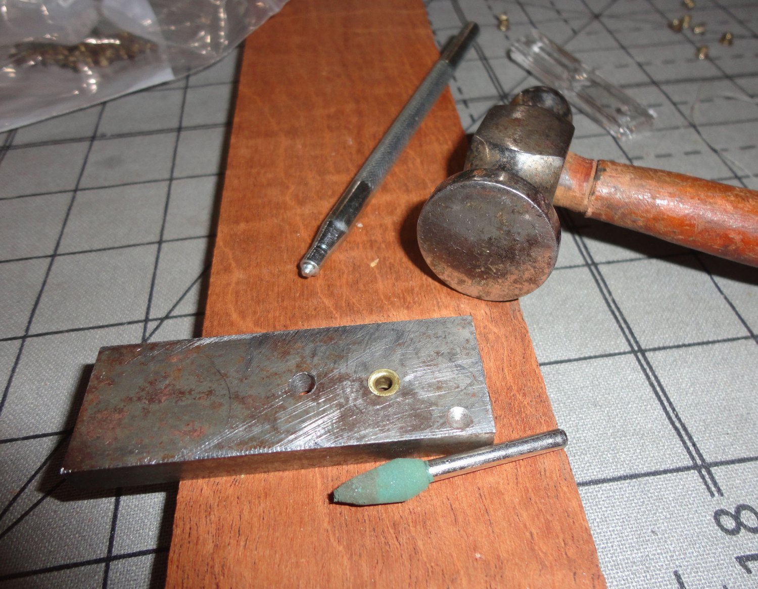
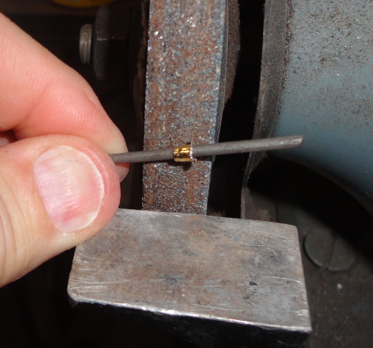
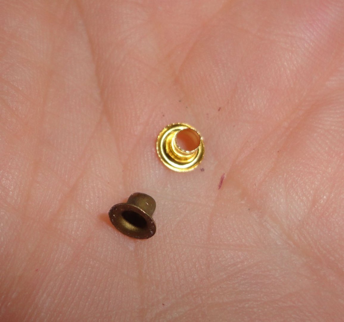
Thanks for the comments on the new stand. A coat of amber shellac was brushed on, 'raising the grain' a little (typical). Once dry, it was lightly sanded and a second coat will soon be on. New-world mahogany is my favorite wood, and less available these days (plus more costly). A French Polish finish is second to none in my opinion. I'll have to make a nameplate. The builder used eyelets as they were, and the degree of flatness varies a bit - so a .125 hole was drilled in a piece of mild steel - with a larger hole for the next size if ever needed. The shank of the small eyelets are about .120 in diameter, so they drop into the hole to set very lightly with a grommet setter (seen in the photo). Then a planishing hammer flattens, a lick of fine sandpaper on the flat plus a little hand burnishing of the hole - and its done. So when all were regularized, the count was 82 ... but there are 42 potholes per side, which means that there were a couple missing initially that I didn't notice, or I've dropped two along the way (more likely). So the process to alter the modern replacements is to first flatten on the die - which makes for a wider face than the originals. Then I used a shear to cut away the excess (with the eyelet on a mini file shank for convenience), as the brass had been work-hardened by the original forming and then the planishing. Then the eyelet was given a few licks of a flat file at the corners sheared, and held lightly to a grinding wheel ... that really made for a nice round periphery. The photo below shows the replacement on the left and an original on the right ... which is a little oblong (not round, as they vary). I'll likely use the wheel to 'round' the oblong ones to make them more uniform. 'Might as well make a number of 'spares', as I'm prone to losing things.


-
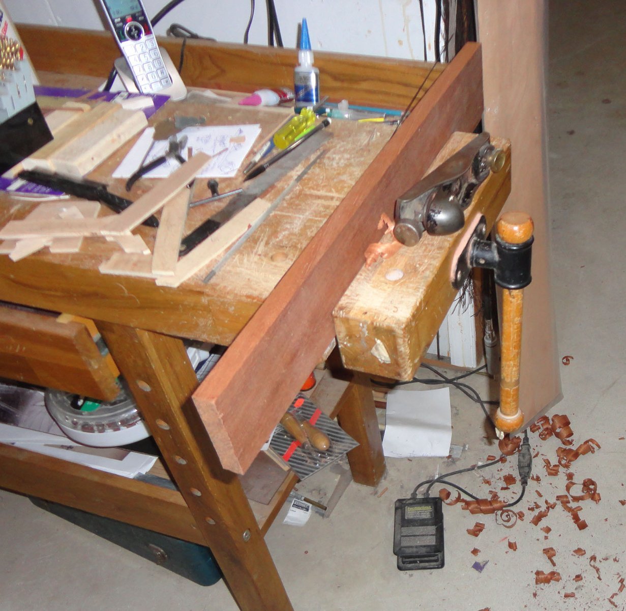
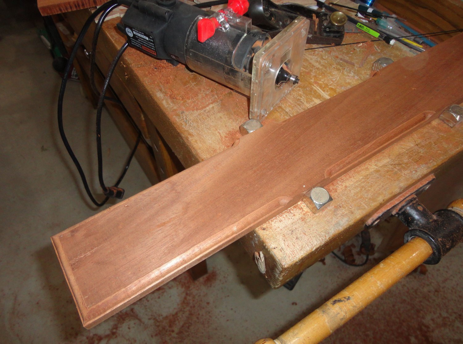
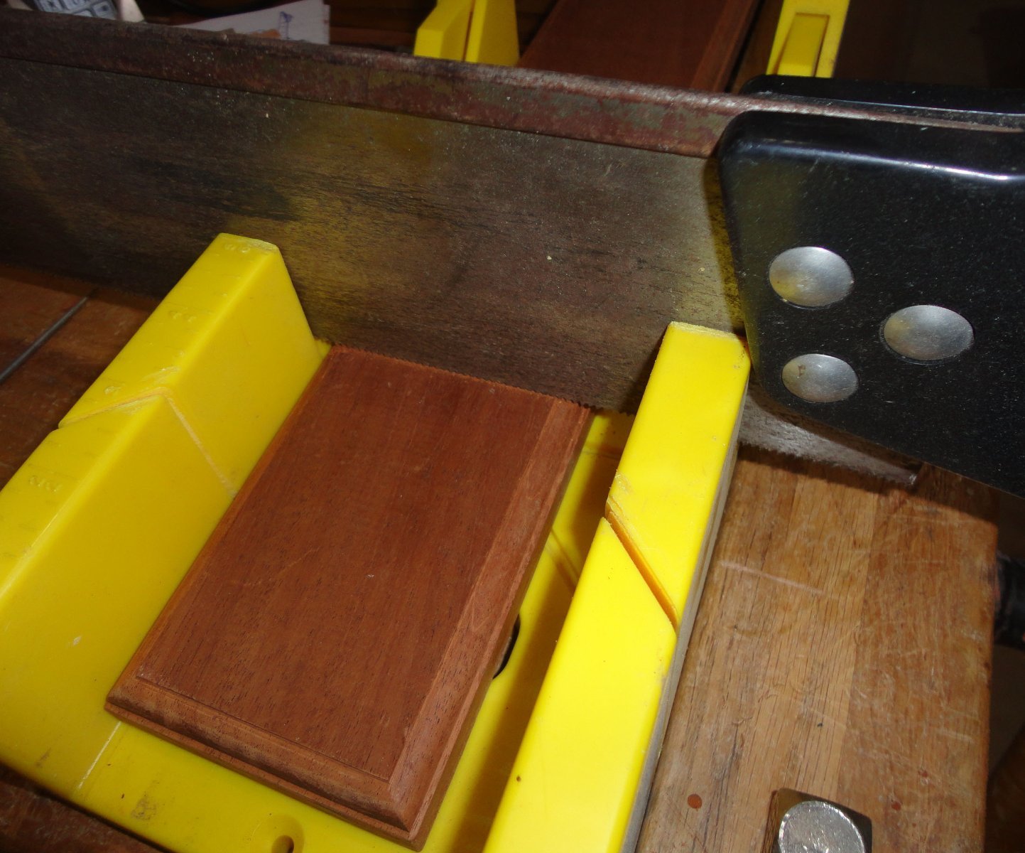
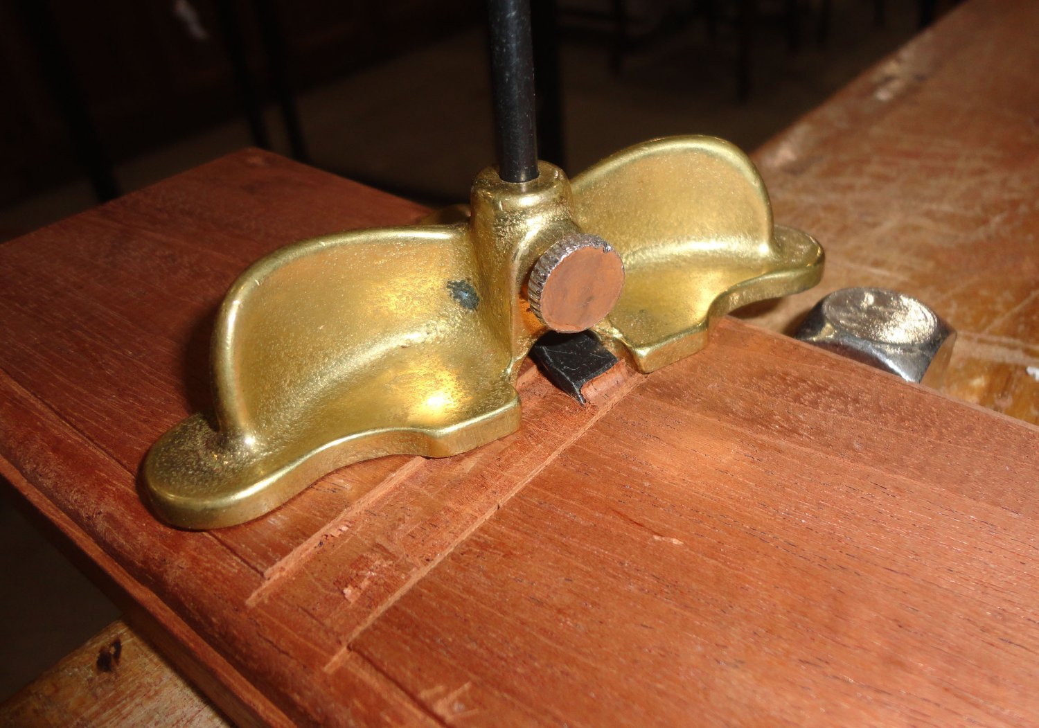
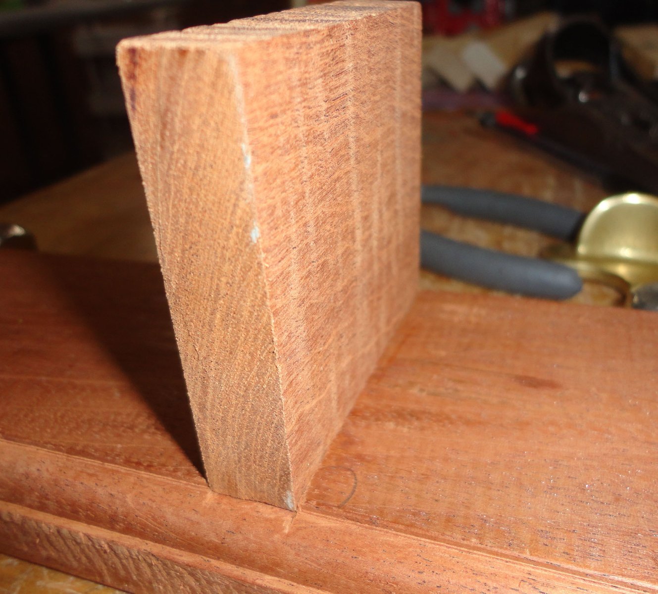
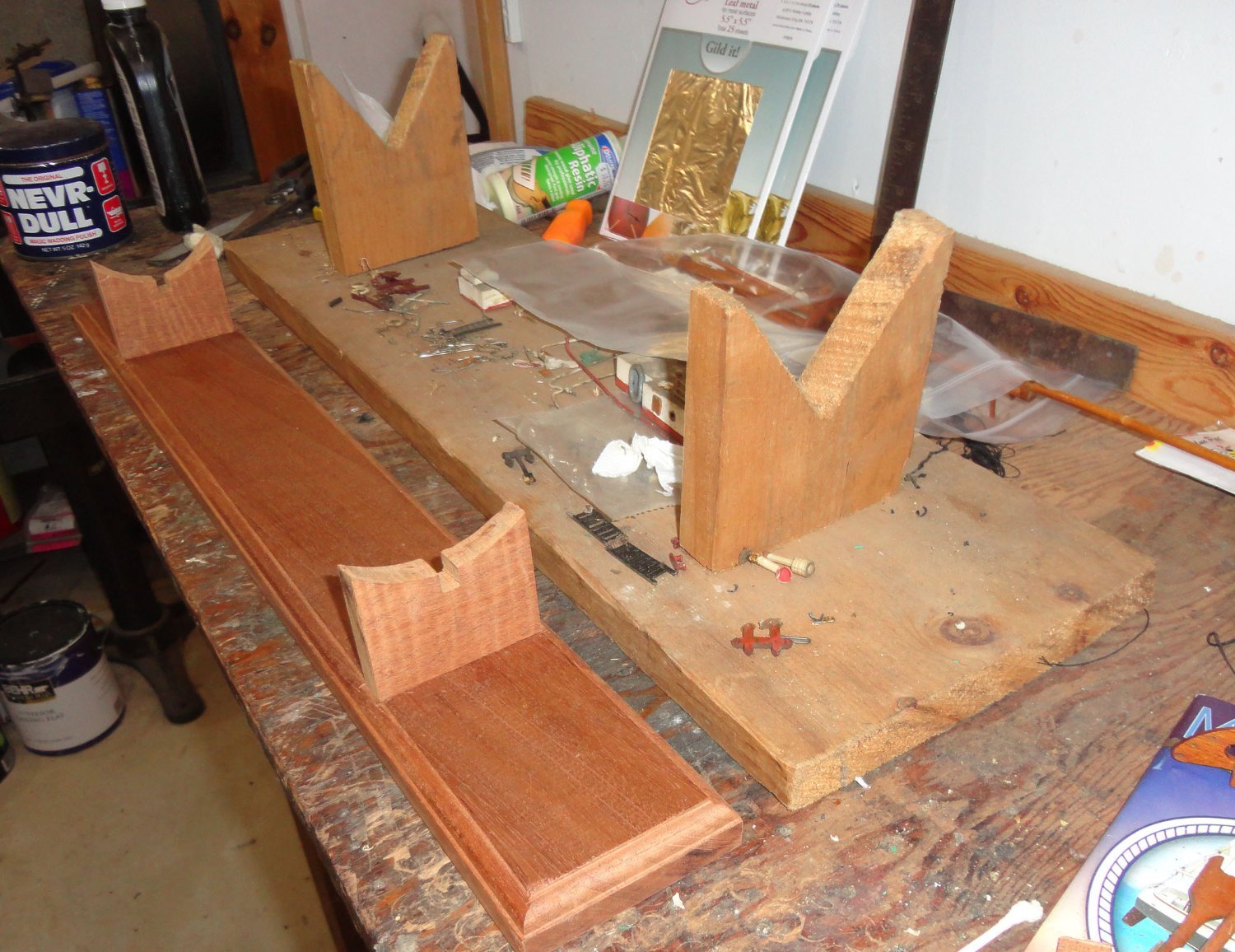
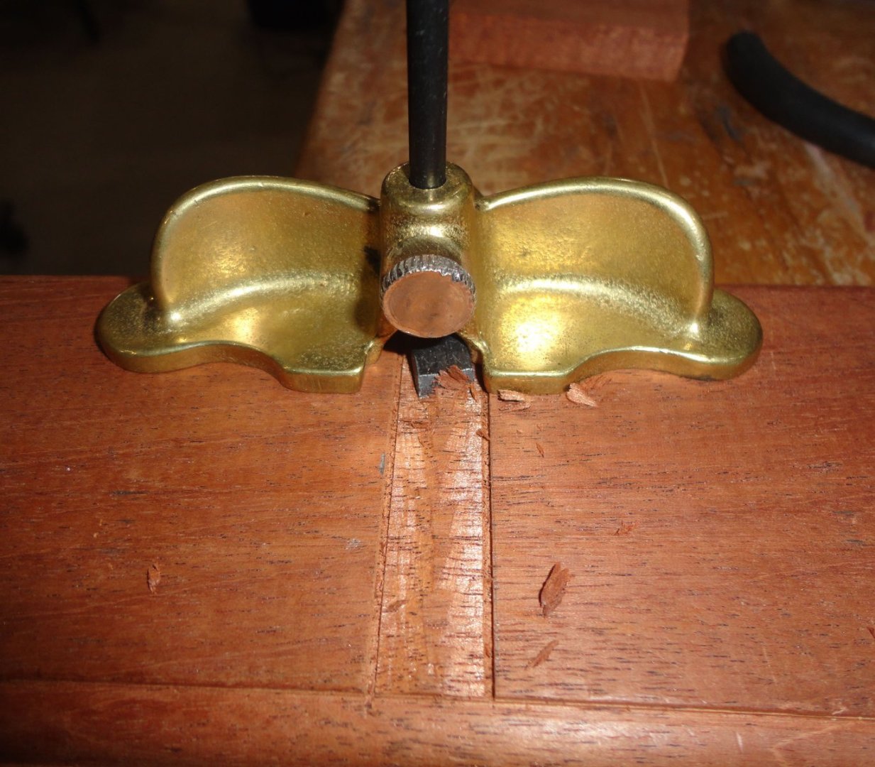
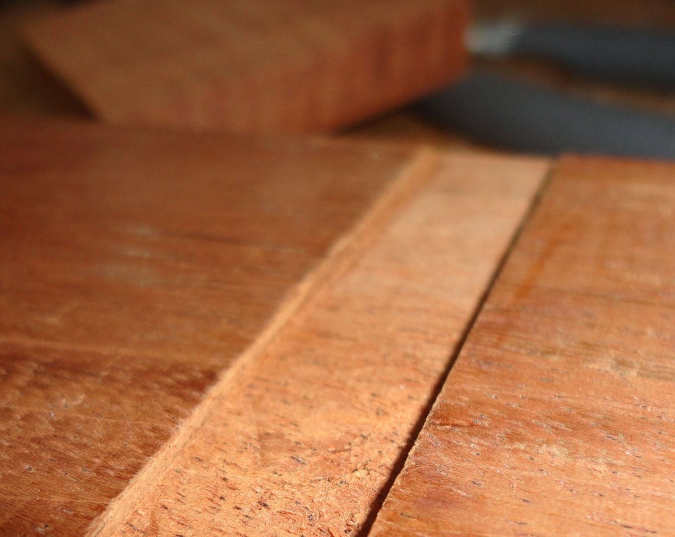
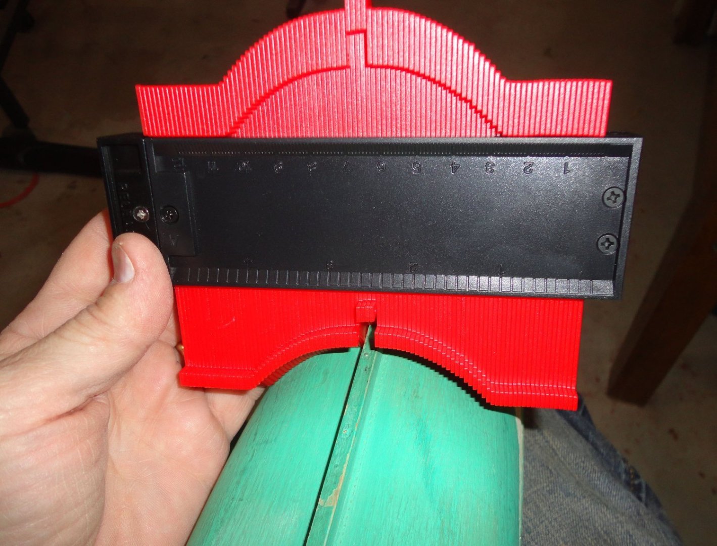
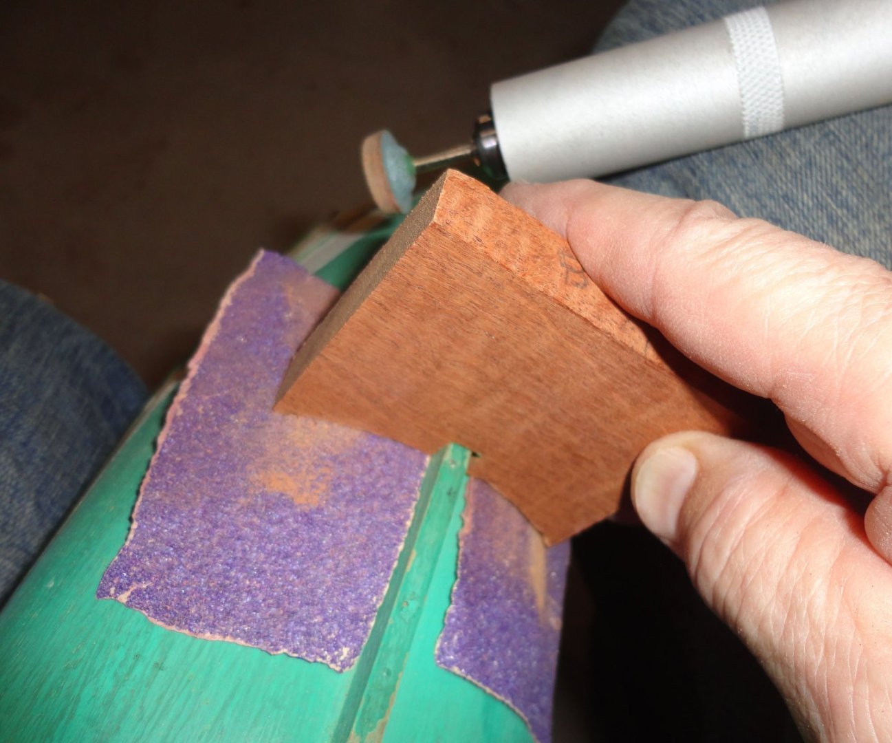
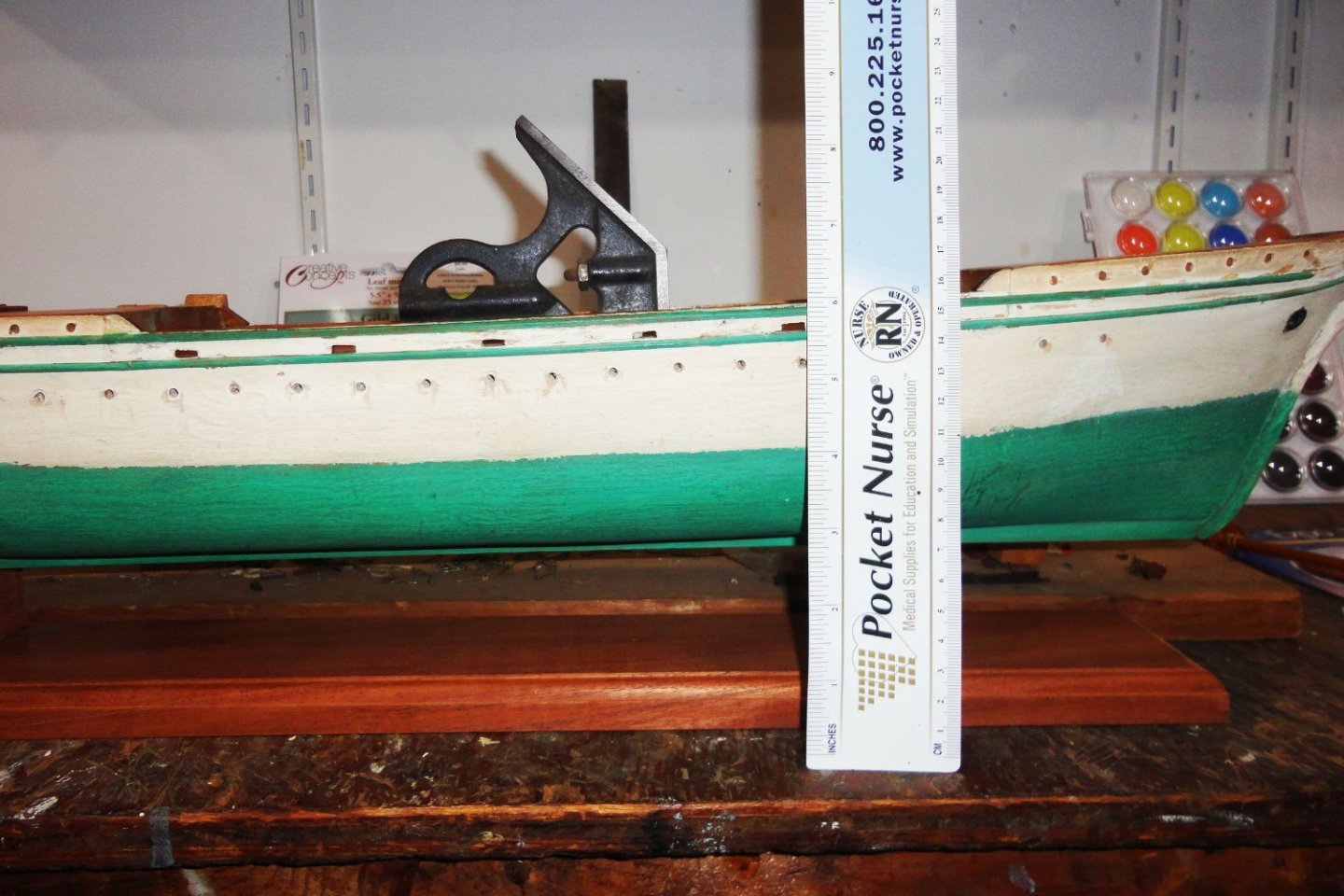
I've always been a 'hammer and chisel' guy, so it was high time I made a better stand for the restoration - the 'as-is' stand being rather crude. A piece of mahogany was scrounged that looked about the right length ... the width ? ... well it seemed OK, and no use 'designing' something that would require buying a new piece. The thickness is 3/4" (standard), and the ends can be trimmed with a table saw, but first the edges needed planing. My favorite low-angle plane set to a light cut (and the blade is kept very sharp) made nice thin curls, once some of the roughness was removed. Its not a proper jointer, but the idea was to remove just a little since the width is on the narrow side - ending up at about 3 1/2". After the ends were table sawn I thought I'd rout a nice recessed quarter-round - inspired by the nice bases that come in the vintage Scientific clipper kits. The photo below is self-explanatory (having avoided the metal pieces pinching the board), and the piece was simply shifted a little laterally to complete the milling. The location of the cradles was judged by eye, then the same measurement was made from each end. My old mitre box was used to hand-cut pairs of limiting lines carefully figured so the cradles should drop into rabbits with a snug fit. Yeah, it might be easier (and more contemporary) to get a right-sized router bit, set up a stop and just make a single pass for each rabbit ... but (being an old-school guy - and having an afternoon to putz over something) using hand tools gives one a lot of satisfaction ... until something gets screwed up. Next up, a small hand router ... given the grain orientation of the base, it seemed wise to set the bit to 1/3 of the needed depth and work 'with the grain' on either side of the margins. The picture below is actually the 2nd pass at 2/3rd the required depth. Once the edges have been shaved, the orientation of the cutter is made 90 degrees to the grain - which shaves off OK since the sides were done first. BTW, those checking this project from time to time will realize my pace is quite slow, with lots of 'thinking' in between steps. No sense rushing, as I'm often quite absorbed doing things, then going off to do something else (many time seasonally influenced or otherwise mandated), then coming back and getting lost 'in the weeds' again. 'Suits me just fine. Below is a full-depth rabbit. 'Turns out the width is nice and snug - one can always trim or sand a tiny bit if needed, as opposed to trying to put wood back on. There's one spot on the edge of the base that didn't quite clean up when edge planing, but I didn't want to take off the additional 1/16" just to smooth that spot. A little sanding can help. I also dropped the base and a small chip came off one corner - but no matter. The truly inspiring scratch build of the Mary Rose gave me the idea to get a profile (contour) gauge. This will transfer the hull shape to the respective cradles before jig-sawing out the waste. I realized that the hull lines constantly change, and that the cradles are about 1/2" thick, so the hull profile of the forward cradle was taken from where the front face of the cradle goes - and the profile on the rear cradle is taken from the stern face. I did mark the pieces lightly in pencil so I'd keep track of how everything needs to go together. Note that the keel is pinned to the solid hull, and the applied trim on the hull is also pinned - a previously noted advantage of a solid-hull model. After cutting the waste from the cradles, a rotary tool was used (with numerous trial fits) to carve the cradle to fit more closely against the hull on the face opposite the one that the profile gauge marked. Then some sandpaper (gripping reverse side paper would have been batter) was placed on the hull so the final sanding was done on the cradles where they are supposed to go. So far, so good ... but a trial fit of the assembly had the hull higher at the bow than it should be. I noted that the deck in the raised stern section curves up, and the deck forward of the main mast curves up going forward (dead rise at the bow). The picture below indicates that the bow cradle needs material removed from its base, and (after measuring) that cradle was removed and pieces of wood stacked to support the bow - adjusted so that the level was level just behind the main mast. I judged how things looked by eye, and was satisfied with how it sat. Re-measuring told me how much to cut from the forward cradle - which was done on a band saw with a guide. Below are the old and new bases side-by-side, and there is a marked improvement. The cradles will be glued, then a pair of screws will be fitted from below as mechanical strengthening.


-
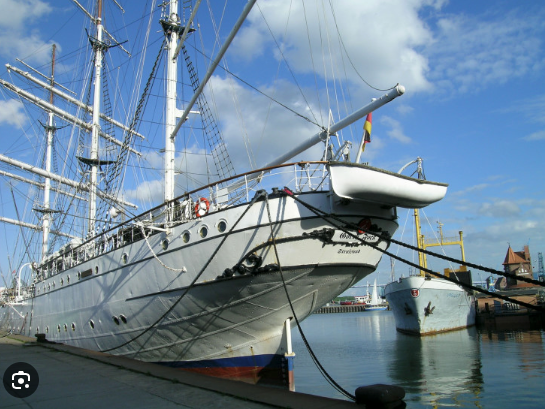
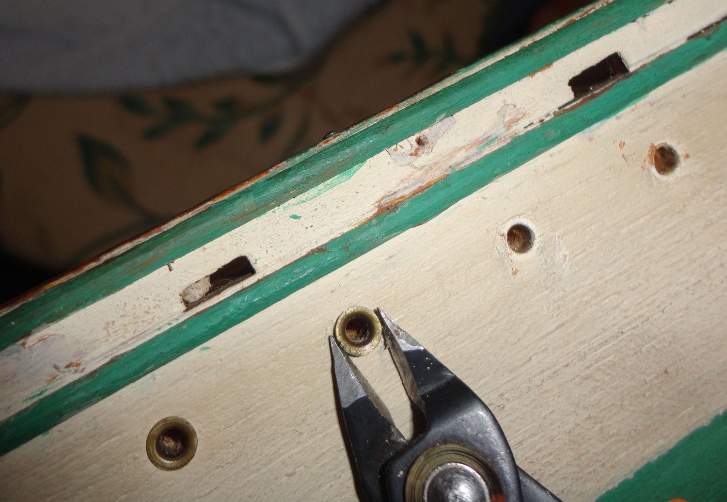
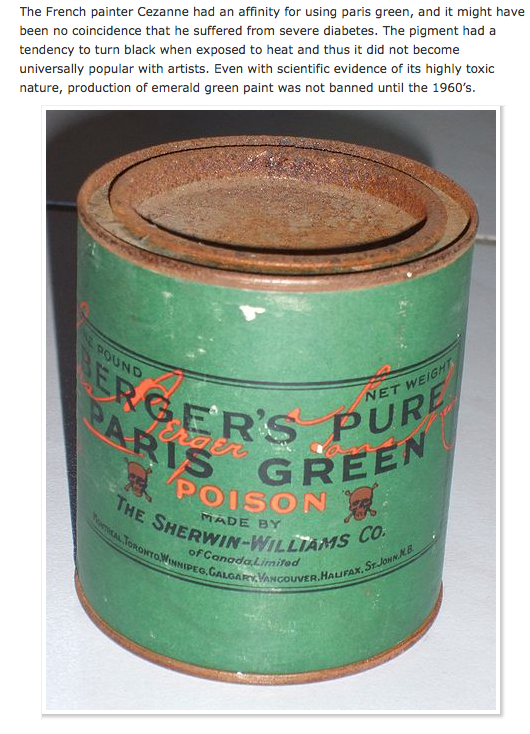
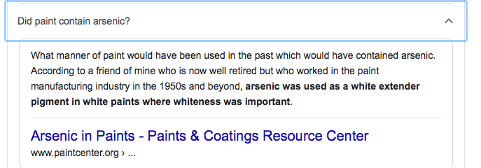
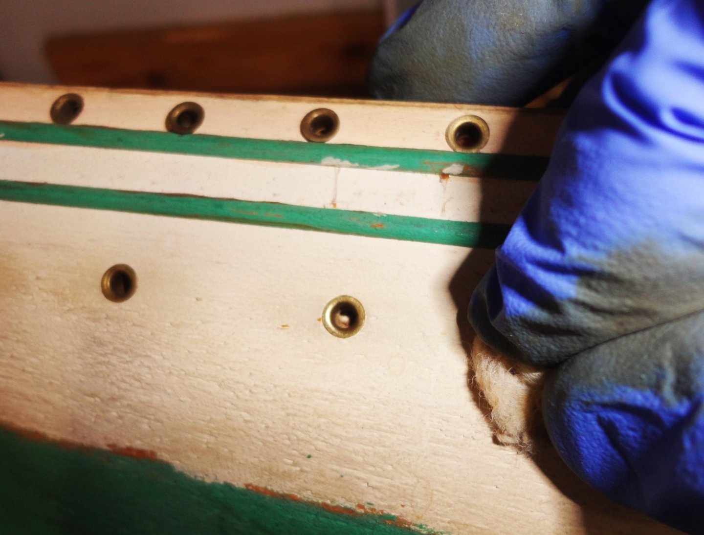
My next step was to remove the original eyelets to lightly sand the hull. The eyelets have varying degrees of flatness to them, so I may make a small die to planish them uniformly prior to re-installation with a little glue. I used flush cutters to get under opposing edges, and they pried out without much trouble. Now I had a good look at the paint, which is uniformly flat, and appears to be an interior casein paint that used to be common, and is consistent with the age estimate for the model. I was the set painter for two High School musicals in 1971, and used this type of paint - specifically, Iddings Deep Colors. They still are popular for theatrical work and interior murals, and has some similarity with artist's gouache. Casein paint goes back hundreds of years, but had to be mixed fresh to avoid spoilage - but was stable once dry ... an historic home in our area still has the original pastel hued paint on much of the woodwork. If re-wet, it could re-activate - so overpainting with a similar paint 'welded' the layers. A method of making an oil-water emulsion during manufacture made the surface less prone to reconstitution, and by the late 19th century methylcellulose additives further improved the product. Preservatives were also developed to increase the unopened shelf life to about a year, and 3 months once opened. Cans of the stuff I used to use were VERY heavy (especially white), because of the lead oxide base ... banned in 1980. So my conclusion is to assume at least some lead content on the hull paint - something to think about on an old model. A test with a moistened water swab and a certain amount of rubbing on the green area did start to pull color from the surface, which began to soften a bit - confirming the paint type. So was there anything else to worry about, given the shade of green? Copper arsenate pigment was widely used from the late 1700s through the mid 1800s for wall paint and wall paper- especially after a more stable form call 'emerald' or 'Paris' green was developed, but died out by 1900 due to the awareness of toxicity and the availability of new and safe(er) green colorants. Yet the use in art colors continued ... Copper arsenate is reported to have been used in early 20th century anti fouling paint, although the most common agents were red lead, cupric oxide and red mercuric oxides. These were mixed with additives in a shellac/linseed type of paint for the U.S. Navy between 1908 and 1926. From 1926, the Navy switched to a coal tar rosin type of paint. Anti fouling paints in the 20th century were generally red or russet brown, but green was occasionally used, perhaps when copper arsenate was in the mix. The Gorch Fock 1 had the green color, but the constituent ingredients are not known to me. Anti fouling paints changed quite a bit after WW2, and have continually been reformulated as there are now World bans on many substances and chemicals considered dangerous to the marine environment. But more to my concern, I found this bit of information: So out of an abundance of caution, I decided to treat the old paint 'as if' there was some arsenic in it. After all, copper arsenate in pressure treated wood was used until 1986 - when a 'safer' inorganic form called 'chromated copper arsenic' was used ... until a voluntary ban in the U.S. and Canada in 2003 ! My sanding was very light, done over a waste can - and mostly to 'skim' off the grime that had accumulated over the painted surface. Then the surfaces were gone over with moist paper towel to remove all dust. Duh, Johnny should have used nitrile gloves ... so washed his hands when done quite thoroughly.

-
That profiler sure came in handy ... I'll likely get one.
-
Since you're doing the HMS Hood, I thought you might like the photo of her at a Panama Canal Lock pre-War ...

-
Electron microscopy shows freshly knapped flint or obsidian goes down to just a couple of molecules wide at the edge ... effectively the sharpest edge for any material to have - as sharp or sharper than a surgeon's scalpel, or Sweeney Todd's razor. This was important for early humans to butcher the mega-fauna they hunted - just getting through thick hides was an achievement.
-
In Scouts, after learning how to use flint and steel, we had to master the bow and drill to make fire. The bow and drill was definitely more difficult, and the carved wooden 'base' was key to accumulating embers to nurture the same way as char-cloth. Once mastered, a Scout was awarded the "Smokey Eyeballs" certificate.
-
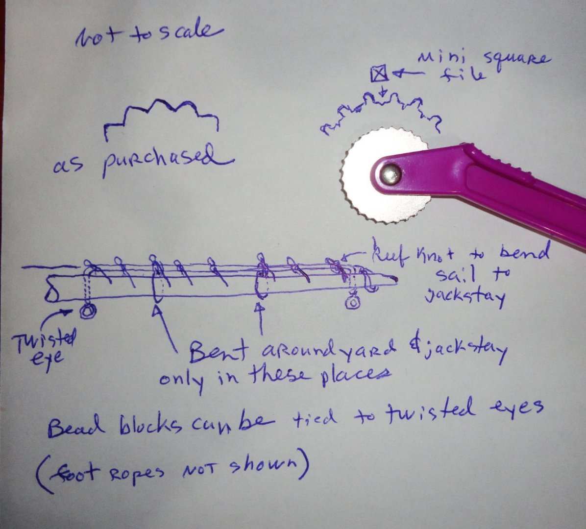
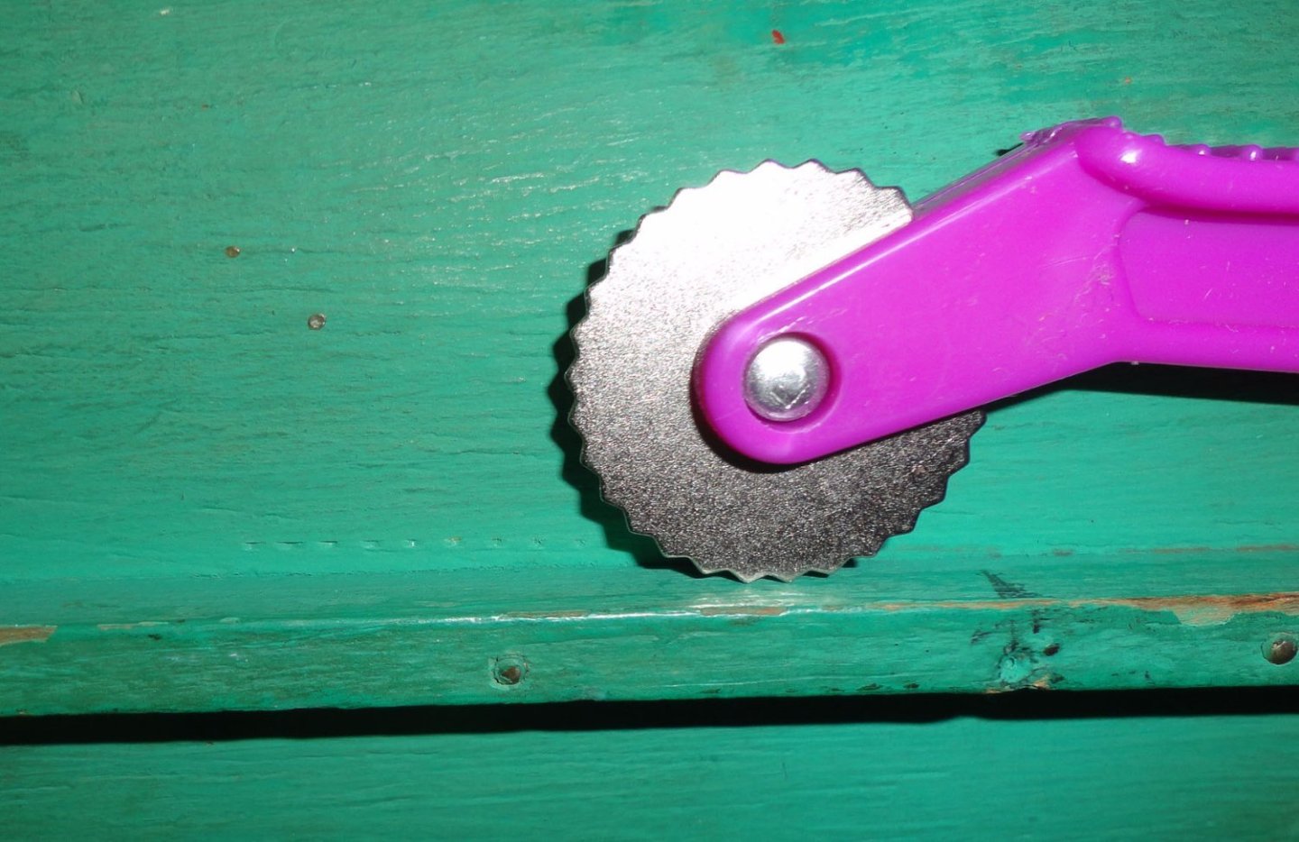
Thanks, Keith. I'll keep that in mind. The flat eyelets used are consistent with the estimate of 70 years on the original, as are other observations. The toothed wheel (unmodified) made somewhat triangular indentations into the wood, so I used a tiny square file to reduce this effect - making the wheel more like 'nubs' - still not sharp. This made for better indentations ( aprox. 0.020" dia. intended to simulate rivets at 1:100) - negative, yes - but just an indication. Burrs from filing wanted to make micro tears in the wood, so burnishing solved that. Light repeated passes (easy does it) were used. More testing is on order before making any decisions. 'Still thinking ahead on some other things - like bending the sails on the yards. Option 1 is to repeat what was found - a single thread spirally wrapped around the yard (going through the sail each revolution). Option 2 would be to used individual ties through the sail and around the yard using a reef knot (just a 'square' knot, but with a bight of line so it can be undone with a tug on the loose end of the bight - otherwise the knot is solid and will stay under tension). Option 3 is in the lower part of the sketch - a piece of wire serving aa a jackstay (not on top of the yard, but slightly on the forward side) where only the ends go through the yard, and are twisted into eyes on the bottom. The sail is bent to the jackstay, but also around the yard at intervals. Some try-outs will be done as tests. As there are no instructions, I'm having to make them as I go ... lots of hours (on and off) thinking about things and how they might work out. Many years ago when building model kits, I was totally reliant on the "instructions" ... assuming that everything was accurate. Hmmmm, a good reason to read and think about everything before hand - including NOT to make assumptions one way or the other on engineering, scale or accuracy. Obviously, most modelers must make compromises - especially at smaller scales - but its good to choose them for a reason. The project at hand isn't even a kit, but if building one, checking out any build of that kit on MSW is a SUPER idea, as there are lots of tips about pitfalls, fixes, and enhancements to pick from.
-
This is a cool way to make a plexiglass case ... as plexiglass cement 'welds' the pieces together, and they can just be lifted off. This gives me an idea - to make a case where there is a solid back with a thin mirrored surface attached. Then the clear panels are the front , sides and top - the mirror enabling one to see the OTHER side of the model.
-
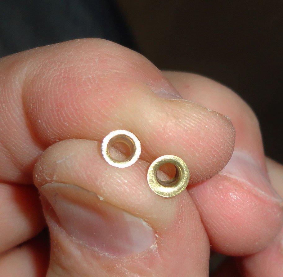
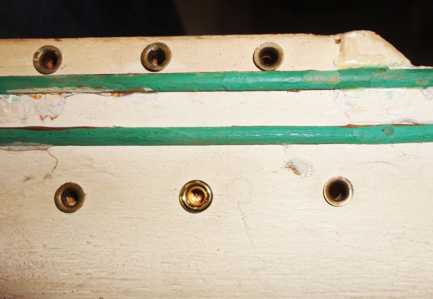
The replacement eyelet was tried in the empty spot ... first, it was a little loose in the hole, and would require pushing a drill bit through to 'right size' it. Second, it just doesn't look right at all, having a more prominent flare and is super-bright - as the photo below shows. That had me thinking of what else I'd have to do to disguise it. One picture is worth a thousand words ... So I resolved to try and find the lost eyelet, and searched all around the shop floor on my hand and knees (the other hand holding a flashlight). 'Thought I'd looked everywhere already (several times) when, at last, I saw something way underneath that looked like it ... and it WAS. I'm resolved to be careful going forward, and perhaps use a little glue when re-installing after hull painting. The well-organized (and neat) builder may never know the sheer joy of finding something that was thought to be forever lost !
-
'Bought some walnut veneer at Woodworker's Supply (there are a couple in our area, so I went to one store to SEE what they had on hand). There was also mahogany and lighter woods in 0.028" thick veneer, sold several pieces per plastic sleeve. The idea is to make my own "plywood" by stacking 3 or 4 pieces together, varying the grain angle and painting a thinned wood glue between the the layers ... then clamping between boards (or weighing them down good) and allowing to cure. This will make thin stock much less likely to break. As for seeing pencil marks on a dark substrate, I use white pencil (comes in other colors) the Admiral uses for marking cloth from patterns prior to cutting. 'Guess its a form of tailor's chalk in pencil form.
-
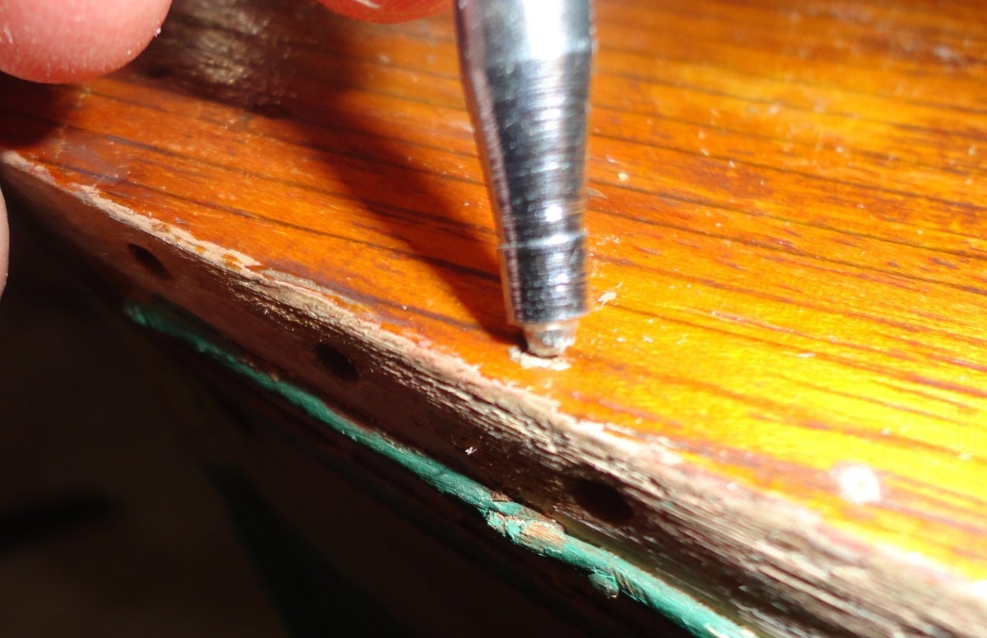
I thought that one of the eyelets might go astray ... and that's what happened to one of them - and dang if I can find it now. I've order some on line, and as there are 200 to a packet there will be plenty as replacements. And if the difference between a replacement and the originals is too pronounced, then new might be substituted for old. The railings will be new brass as well. I told both the lazy imp and the Hatter to stop kibitzing and get lost. It turns out that the paint on the heads of the pins (fake rivets) on my test piece previously posted, flakes off easily due to the smoothness of the metal surface. To get paint to stick, I'd likely have to use bent pliers to grip each pin shank and roughen the surface of the smooth head on fine sandpaper to give it some "tooth" for the some primer to grip. This really makes the idea impractical, and has been suggested is inappropriate for this project. I do like the look of riveted plating as seen on the build of the Ergenstrasse elsewhere on MSW. A test was done in an inconspicuous place near the keel with a 'dull' sewer's pattern marker (there are 'sharp' versions as well), and there are slight depressions that look interesting. When painted over they'll partially fill, but still give a slight impression of rivets. At a distance they'll hardly be noticeable. There is the stand to build, as the present one is rather crude. I like the ides of making cradles so the hull can be picked up and replaced while working on it. Later for display, screws from below (or simple pins, perhaps) can fix the hull to the stand so it does not shift if the case (to be built last) is moved. I need to drill a hole for a new bowsprit if joining the original with a steel pin does not work out - replacement being 'plan B'.
-
Ded reckoning: A means of finding rocks and shoals.
- 106 replies
-
- 2
-
-
- Soleil Royal
- Ship-of-the-line
- (and 2 more)
-
Really nice job, Steve! If using a Dremel, rotary tool with flex-shaft or dental drill, a succession of 'ball' head bits will generally tackle interior wood shaping like you needed to so. The putty trick (after partial shaving) seems like a time-saver (and less trouble).
-
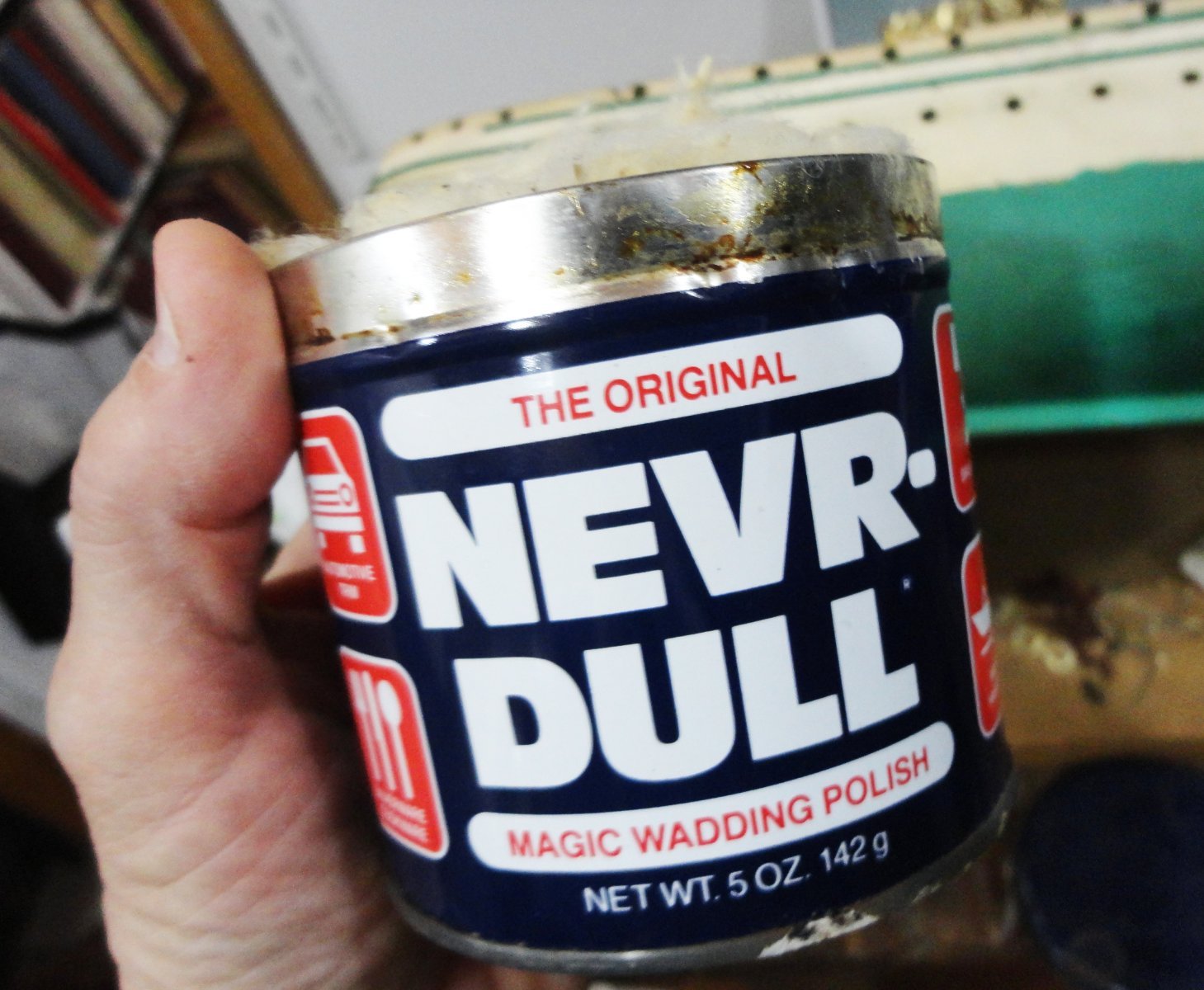
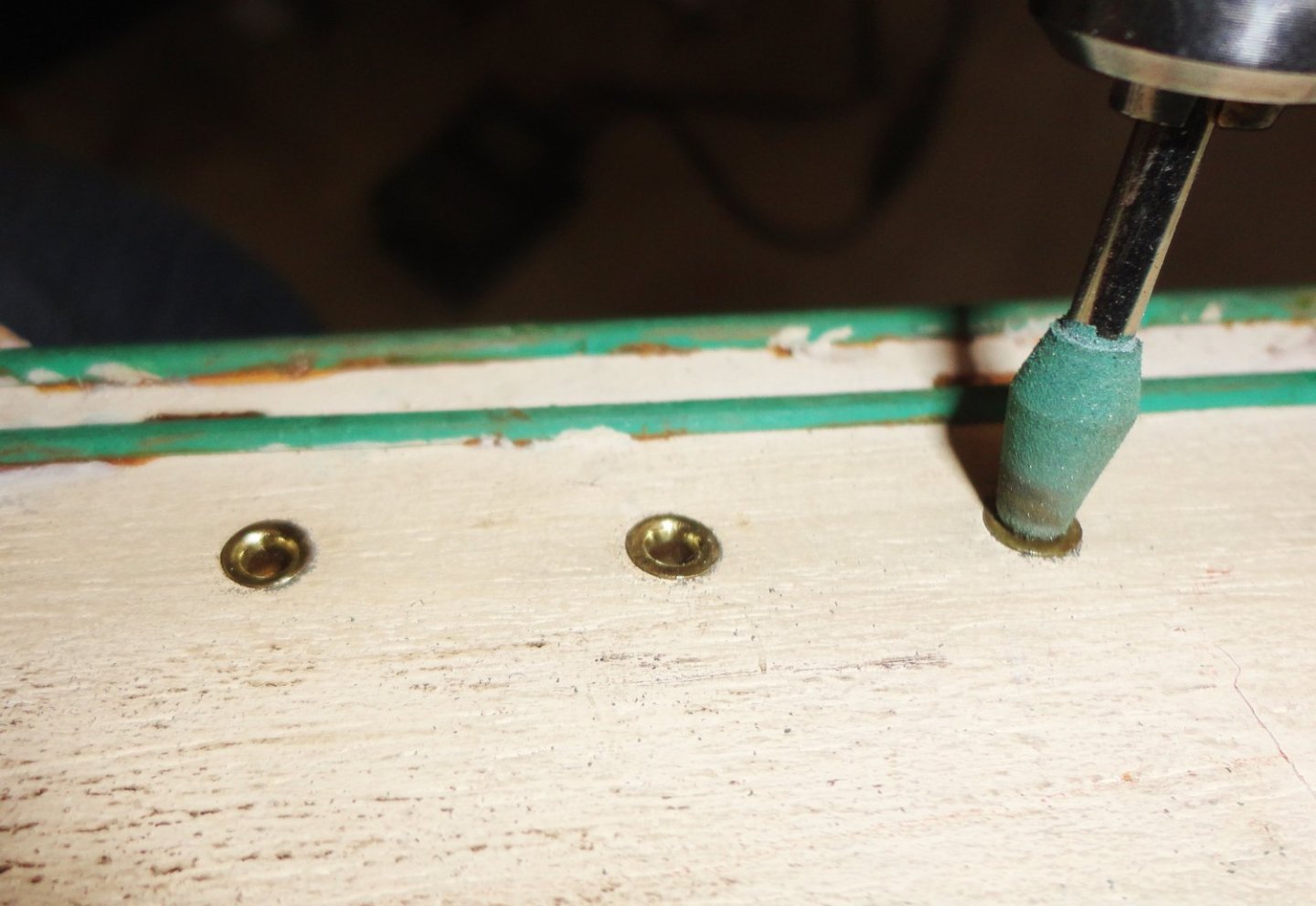
I found that a dab of Tarnex (liquid silver polish) applied with a cotton swab (Hmmmm, could also swab the barrel of a miniature brass gun with a suitably sized bore) was the first step in neutralizing excessive tarnish on the eyelets. this was done in situ for convenience. Then a light rubbing with Nevr-Dull shined the flange exteriors. I wore a nitrile glove so not to blacken the finger tips. Step 2 Step 3 was to lightly work the rounded surface of the eyelets formed inwards with a soft rubber bit for the rotary tool. The eyelets will be carefully removed to permit light sanding and repainting (plus some blackening inside the hole into the wood). The railings will be new brass, so the eyelets and railing will then acquire a natural patina over the years at roughly the same rate.

-
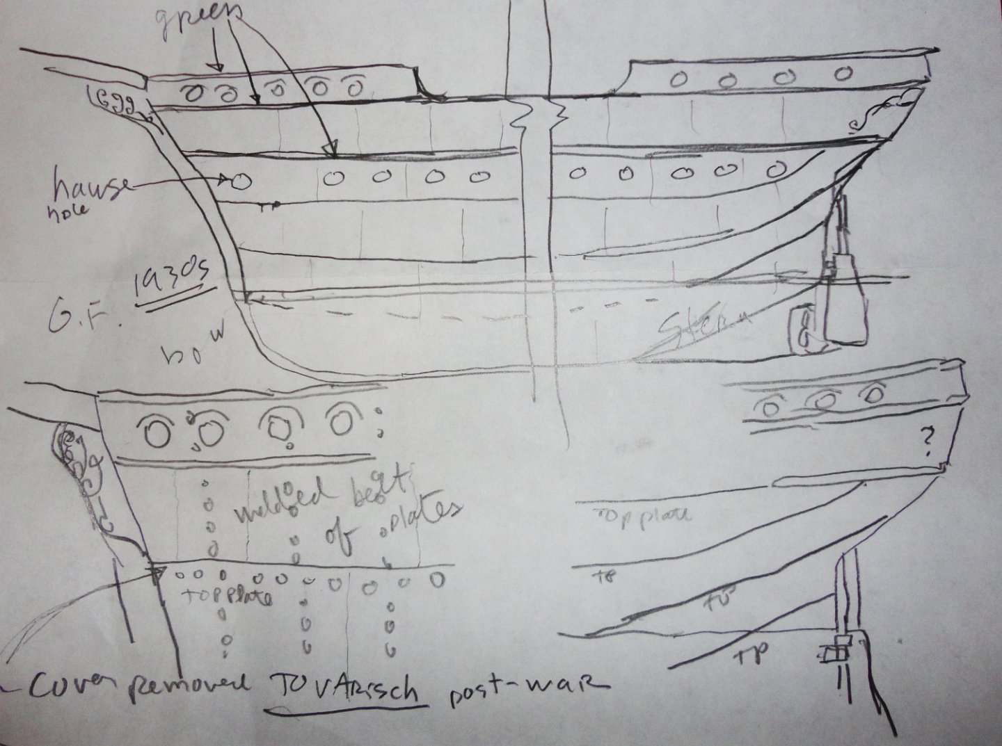
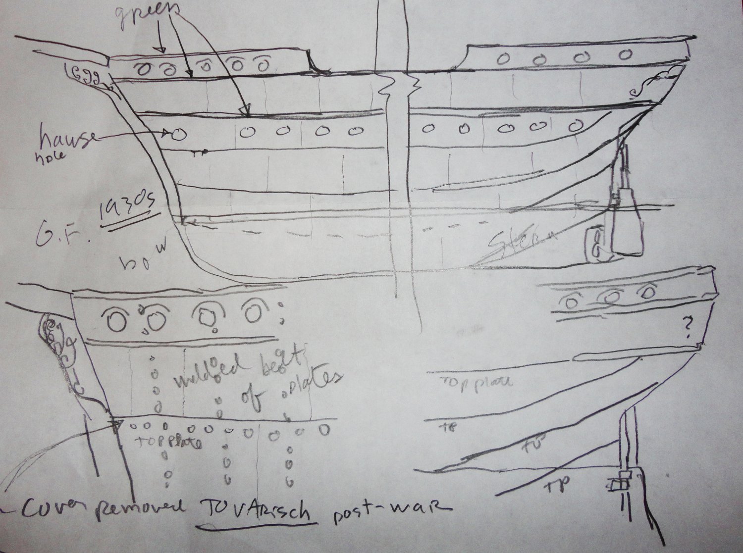
A good re-direct, Keith. So often I'm overthinking various aspects of whatever project I'm on at the time - in part because there is almost never a re-do. Past projects of various kinds represent closed chapters, yet sometimes there are thoughts like, 'What if I'd done it a little differently?' So imagining all sorts of ways to progress on a present work still means that I have to choose a certain way to go. Having discarded other paths not taken, there will be no 'what ifs' concerning them since they were consciously set aside. Only if I later think of something NOT mulled-over prior to acting will I muse over it. But there has been progress in doing less of that, in part by doing more thinking beforehand ... which may drag something out - but maybe its better than rushing in. In the present case, I'll keep the original eyelet-ports in the spirit of restoration. The upgraded deck railings are brass, and I don't care to paint them - so they'll go with the eyelet ports. I'd like to use many of the deck fittings from the original model, such as they are, where possible. The fife rails will have to be re-done, in light of the improved rigging (simplified, though, as previously planned) - a main interest in doing this project. Every line has to have a purpose and means of operation. While the hull is stripped bare, I may still do a little on it, in that photos of the original (as modified) still show some obvious horizontal join lines. The present incarnation has them welded over for strengthening - which only emphasizes them more than when they were just riveted as she existed in the 1930s. The lower green belt is discontinuous today, but was continuous as built. Each horizontal 'belt' of steel was composed of neighboring plates welded together pretty flush, so those joins are not obvious. The belts follow the lines of the ship and are not unattractive - rather , they provide interest. Another 'thumbnail sketch' was made to think about these belt lines for consideration. I'm also seeing some advantage to a solid hull - at least for ships that have painted hulls (with or without copper bottoms). There is always something solid to 'pin into', whether eyes, chainplate or whatever. And solid hulls are 'old school' carving projects. I'd likely use a drill press to make mast holes while the wood is still a block, setting a mast angle (if any) by shimming one end of the wood block to suit. Obviously 'Age of Sail' men-of-war with multiple gun decks can benefit from planked construction, and any ship that was largely unpainted. And most kits have laser-cut frames to plank. Yet the time saved by not carving is taken up by everything involved with Plank-On-Bulkhead. One may want to add additional intermediate frames, wood filler blocks (hmmm, so it starts to resemble a solid hull), then fairing like hell, then first planking - filling - sanding - putzing, before ... second planking.