Thukydides
-
Posts
1,366 -
Joined
-
Last visited
Content Type
Profiles
Forums
Gallery
Events
Everything posted by Thukydides
-
Welcome, you have made a great choice for your first build. I also came to wooden ship modeling from plastic models and you will find some this translate well and others do not. I would highly recommend starting a build log. Good luck
-
 I suspect in many such cases the sources just didn't show the details. Every primary source example I have found which intended to be accurate at that level of detail shows some sort locking mechanism. Granted I mostly look at British stuff. Also every contract I have read makes mention of locking the wales together often specifically mentioning the joint they are meant to use. That is not to say that some of the strakes on the wales may have been joined in butt fashion, just that some of them would necessarily have been locked together.
- 142 replies
-
- 3
-

-
- Christiania
- Vanguard Models
- (and 1 more)
-
A scarf joint is much more secure. In addition to what you can see there was also an indent in the scarf that held the planks together. It would impart much more latera strength. The wales were the main structural part of the hull holding everything rigid (hence why they were thicker). The scarf essentially locked the planks together. They were frequently used on joints all over the ship that required more strength or were more structurally important. For example the keel would have had scarfs to hold n the pieces together, you just don't see it because they are facing vertical instead of horizontal in this case. If you consider the size of these things the scarf is not actually that small and there is plenty of room for a treenail. That being said scarfs were not the only thing used to lock the planks together. British shipwrights (particularly for smaller ships like the sphinx class, which the kit here is based on), would often use what is called top and butt planking. It essentially uses planks in the shape of a lopsided anchor stock to lock two strakes together. Of note they often also used this for the planking under the wales as well.
- 142 replies
-
- 3
-
-
- Christiania
- Vanguard Models
- (and 1 more)
-
Great to see you back at it. I look forward to seeing what you make of this given your previous work.
-
Ok thanks, I will have to some more digging. Like everything it seems like things are always more complicated than seen at first glance.
-
I am currently working on the bollard timbers / knight head and I have run into some confusion. I am hoping that someone has some insight to share Many of the fully framed models I see on this site have the bollard timbers jut out just below the top of the stem so that the planking ends at the side of the timbers instead of in the rabet of the stem. For example see the below explanation from Chuck’s Winchelsea plans, but this process is replicated on others such as @druxey’s swan class practicum and the HMS Naiad by Ed Tosti. https://syrenshipmodelcompany.com/resources/Chapterone (1).pdf I would normally not question the methods of these very skilled individuals, but when I look at the plans for Perseus and the other sphinx class the knight head seems a bit thin and I see little evidence for this extension. For example: The framing plan for sphinx seen here does not appear to show a hard extension. If the bollard timbers are proud of the planking, it appears to be a gradual transition. The as built plans for sphinx ships (many could be found, but here is one example) are similarly unclear, but some appear to show the planking line continuing all the way up to the top of the bulwarks. The planking expansion for sphinx does show a gap at the bow (see here), but it is much too high. The top of the stem is roughly level with the top of the foremost port. As you can see in the expansion the gap does not start until two strakes higher than that. This suggests to me that this gap is only there to allow the top of the knight head to stand free. The AOTS Pandora book depicts pandora with planks over the bollard timbers. Now I don’t normally consider this book reliable (I have already found too many innacuracies), but I am wondering if their assumption in this regard came from somewhere. Alex M’s excellent sphinx model appears to plank over the bollard timbers. So in conclusion I am wondering if the practice of having the bollard timbers standing proud of the planking and having the planking end against them was a universal practice or if it depended on the ship. Is this just somthing that they didn’t bother to depict on the plans because it was always done and there was no need to show it. Are there some examples (particularly contemporary ones) that you know of where the planking went over the timbers?
-
Now that is really interesting. I would have thought they still would have one (even just for transporting water or supplies back and forth). Out of curiosity, where did you find that detail?
- 4 replies
-
- 1
-
-
- Adder
- Vanguard Model
- (and 1 more)
-
I have a copy of May's "The Boats of Men of War", he talks about the boats carried by various ship types. I will take a look and see what he says for brigs of the period when I get home. Edit: Steel lists ropes for a launch and one of a pinnace/yawl/cutter though that doesn't tell you the sizes. https://maritime.org/doc/steel/tables/pages/138-BrigOf160Tons.php
- 4 replies
-
- 1
-
-
- Adder
- Vanguard Model
- (and 1 more)
-
Welcome to the forums. Your models look great. I have a soft spot for Alert as it was my first wooden model. I will be following along to see how this progresses.
-
Yes, it can all be a bit funny. Coincidentally Perseus likely had 12 swivel guns in addition to the 20 9pdrs and the 8 12pdr carronades. I have some ordnance stores records (Appendix B, the 2nd entry, they are the 1/2 pdrs) from the 1790s listing as such. I also have entries from log books describing the firing of swivel guns in 1781 (after the addition of carronades). That was my big concern is there is some discussion in the literature (maybe Caruana, I can't remember for sure) that swivel guns started to disappear after the advent of the carronade. However, I do have evidence that at least in the early 1780s Perseus was armed with both.
-
So all my carronade and gun talk is in my internal draft (you won't find it in the file I posted in my previous post). The carronade section is mostly done, it is just waiting on my cleaning up some of the references and adding in some illustrations on my todo list, cleaning up the language etc. If you want to see a rough draft of what I have done, I am more than happy to send it to you, just it will have a few placeholders, incomplete citations, and missing images. Yes my research says pretty much the same thing regarding carriages, though for the really early adopters things are less certain as there was lots of experimenting going on. I have found some evidence of wheeled trucks, as well as inside principal methods being used in the very early days, but I think they were not common. I plan to depict the carronades using the outside principal. I am mostly settled on the carriage design for the carronades based on the National Archives drawings reproduced by Caruana (I assume that is where your design came from because they look pretty much the same).
-
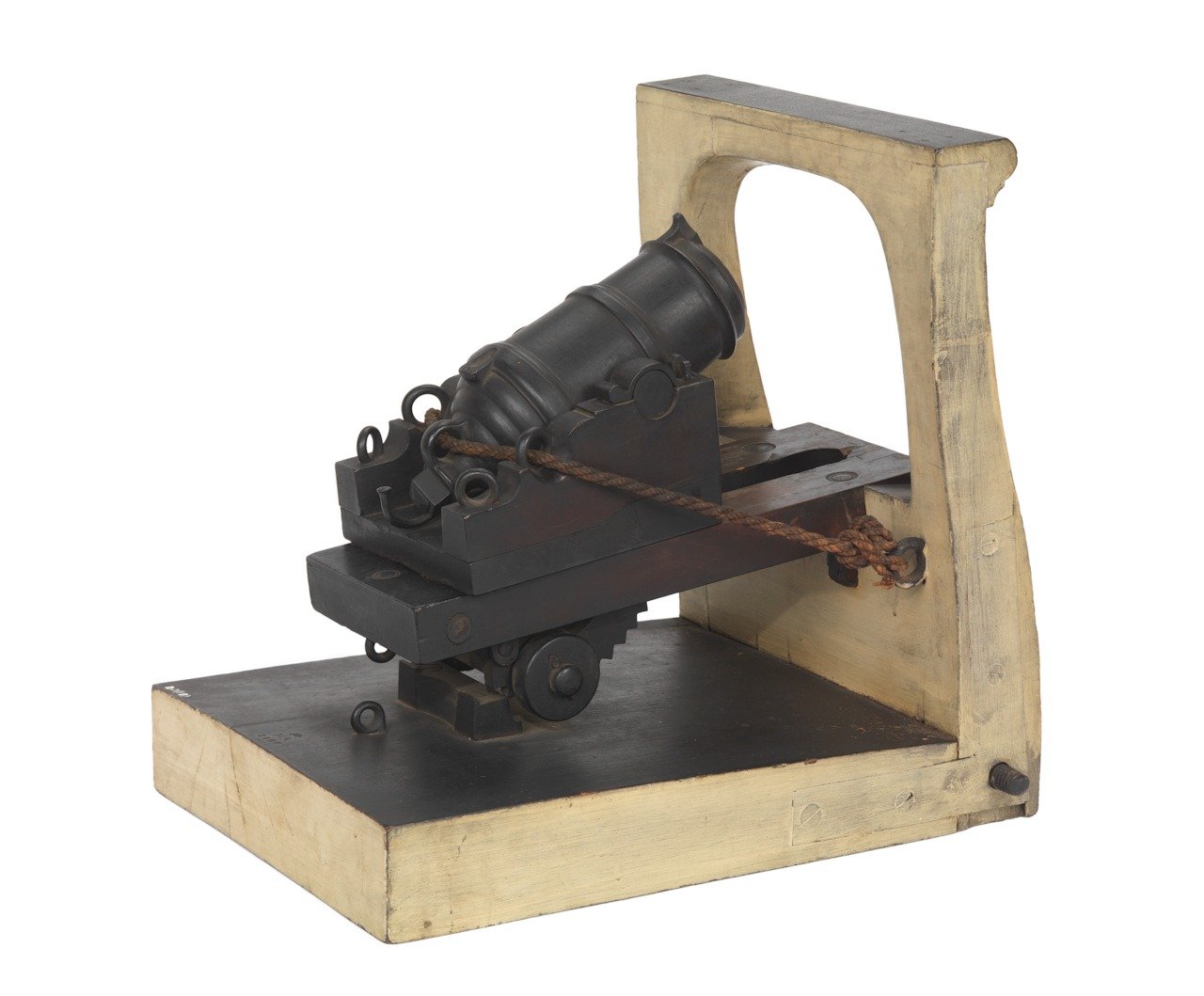
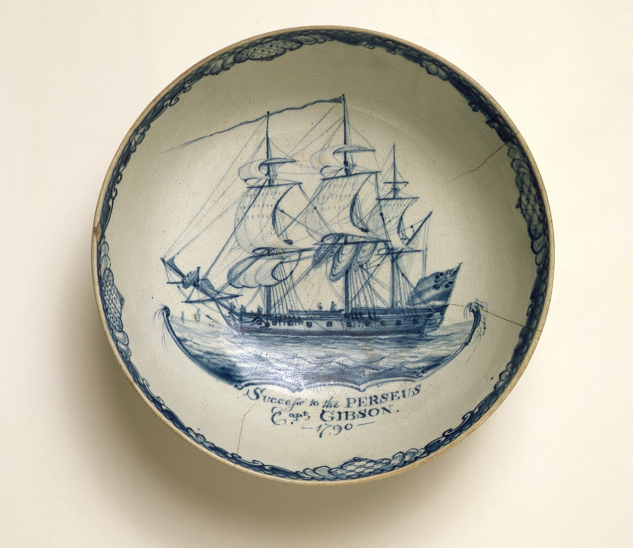
Log #33: Carronades on the Perseus Thank you to everyone who has stopped by. I am actually back working on the model, but I don't have much to show yet. Hopefully I will have some progress to update soon. So in the meantime I thought I would follow up v2 of the research document with another research post. One of the most significant visual features of a ship model are the guns and in the case of Perseus in 1780 (the time period in which I am depicting her), there is a degree of uncertainty as to her exact armament. What follows is a discussion regarding the number and nature of carronades that were likely present on Perseus. When I publish the next update to the research document, it will also include discussion of the other Sphinx class ships in the section as well as the usual detailed citations for the primary sources referenced. Carronade Model Date Unknown National Maritime Museum, Greenwich, London. SLR2915. One of the most common early uses of the carronade was to upgrade the armament of the quarterdecks and forecastles of 5th and 6th rates. It should however be noted that carronades were not considered part of the official armament of the ship. Perseus would still be referred to as a 20 gun ship despite any potential carronades on board. The order in council recommending the use of carronades on Royal Navy ships is dated 28 July, 1779, but it is clear that the implementation of this was varied. The below table shows the earliest possible point at which each of the Sphinx class ships could have been equipped with carronades based on the start of their first recorded refit in England after that date. Two of the Sphinx class ships, Vestal and Ariel, were lost prior to the introduction of the carronade. In the case of Perseus, we know that carronades were being equipped to her contemporaries while she was undergoing refit in Chatham in 1780. A letter from William Sugden dated July 1780 includes orders to lay up Perseus, but also to fit two carronades to the Surprise at Sheerness. First Refit Following the Introduction of the Carronade, Sphinx Class Name Refit Date Refit Location Unicorn Sep-1779 Portsmouth Ariadne Feb-1780 Unknown Daphne April-1780 Sheerness Perseus 2-July-1780 Chatham Sphinx Feb-1781 Deptford Narcissus 9-May-1781 Plymouth Camilla Jul-1782 Chatham Galatea Oct-1781 Sheerness In December 1780, Perseus along with the Schooner Racehorse and the Cutter Expedition encountered a French privateer in the English Channel south of Eastbourne. The account of one of the officers of the French privateer, the Comte-D’Avaux describes the engagement and subsequent capture and sinking. Of particular note is the fact that he describes the Perseus as being a frigate of 26 guns. The Comte-D’Avaux was already seriously outgunned by the three ships chasing it so there was no need to inflate the forces it faced. There is also no reason to think that the officer in question was mistaken as he was an experienced seaman and so it is likely that he at the very least saw gun ports to inform his statement. The lack of reference to carronades vs guns is likely due to the fact that from a distance, the two would be hard to distinguish and the carronade was a new weapon at this point that the French were not generally aware of. The Captain’s log for Perseus from this period also mentions firing carronades twice. The first of these entries, dated May 16th 1781, describes how when firing a broadside at a cutter, the spritsail yard arm was shot away by “one of the forecastle carronades.” The second entry, dated July 24th, 1781 describes firing a carronade to signal a member of the convoy to keep their station. A report dated 22nd July 1782 in the collection of Admiral Charles Middleton, who at that time was the Comptroller of the Navy, lists 158 Royal Navy ships supplied with carronades including five Sphinx class ships. What makes this record particularly interesting is the armament for the Sphinx class ships is not all the same. Ariadne, Daphne and Perseus are listed as being equipped with the establishment recommended armament of 2 12-pdr carronades on the forecastle and 6 on the quarterdeck. However, Sphinx is described as only having the 6 carronades on the quarterdeck and Unicorn as having 2 carronades on the forecastle, but only 4 on the quarterdeck. A further complication with regards to the established compliment is a note at the end of the 1782 list. It states that from the 9th March 1780 onwards carronades were only provided at the request of the captain of the ship in question. This highlights the fact that captains had considerable latitude in this early period of adoption. Lavery, referencing Admiralty letters, notes that around this period “it was agreed that the establishment should be relaxed” due to the push back from many captains who felt that the carronade were “of little use in the Royal Navy. The fact that the list dates from the period between the end of Dacres’ command and the start of Roy’s makes the possibility of the armament having changed since the 1780 privateer account plausible. The RMG has a bowl depicting HMS Perseus in 1790 which shows her with a built up quarterdeck, but not forecastle. If the bowl’s depiction is to be trusted, it potentially suggests that Perseus likely had carronades on the quarterdeck, but not the forecastle. No clear gun ports can be seen in the painting, but this may simply be due to the rough nature of the image. The built up quarterdeck is consistent with the account of the French privateer which suggested only 6 carronades, but it is also possible that despite the lack of bulwarks, there may be carronades on the forecastle not visible in this image. Bowl Depicting Perseus National Maritime Museum, Greenwich, London. AAA4434. In his book The Naval History of Great Britain, William James reproduces a list of ships ordered to mount carronades that were in existence on the 1st of January, 1793. The list contains 40 RN ships including three Sphinx class ships, Ariadne, Daphne and Perseus. They are listed as having 2 12-pdr. carronades on the forecastle and 6 12-pdr. carronades on the quarterdeck. This armament record is consistent with the planking expansion for the Sphinx from 1799 which shows 8 additional ports necessary for the carronades. In conclusion, the weight of evidence suggests that Perseus was equipped with 8 12pdr carronades during her 1780 refit and kept them until her conversion to a bomb vessel in 1798. The most serious challenge to this view is the account of the French privateer which implies that Perseus was equipped at that time with 6 carronades. This can however be resolved by noting that the depiction Perseus on a bowl shows the quarterdeck bulwarks built up, but not the forecastle ones. If this arrangement was present in 1780, the lack of gun ports on the forecastle may have lead the privateer officer to miss the forecastle carronades. It is also possible that Perseus’ initial armament was just the 6 carronades and that two additional ones were added to it sometime after the engagement of 1780, but prior to the list in 1782.
-
Resin ice effects
Thukydides replied to JKC27's topic in Painting, finishing and weathering products and techniques
You could look into crackle medium, I am not sure if it would work at your scale, but it is a way to get that sort of look for ice. The other option I can think of is to create a sort of tray for the base. Then paint the bottom of the tray to look like deep water, followed by covering it with resin. While the resin is partially cured (you will have to experiment with this to figure out the right time), place plastic (or resin) shards representing the ice pans on top. The below video shows the idea used on a miniature figure base. Note he is doing it for a much larger scale so you will need to adjust accordingly. -
Sorry to hear that Joe.
-
But just remember how great it will look. Then as time goes by you will forget how painful it was and end up doing it again :).
- 142 replies
-
- 2
-
-
- Christiania
- Vanguard Models
- (and 1 more)
-
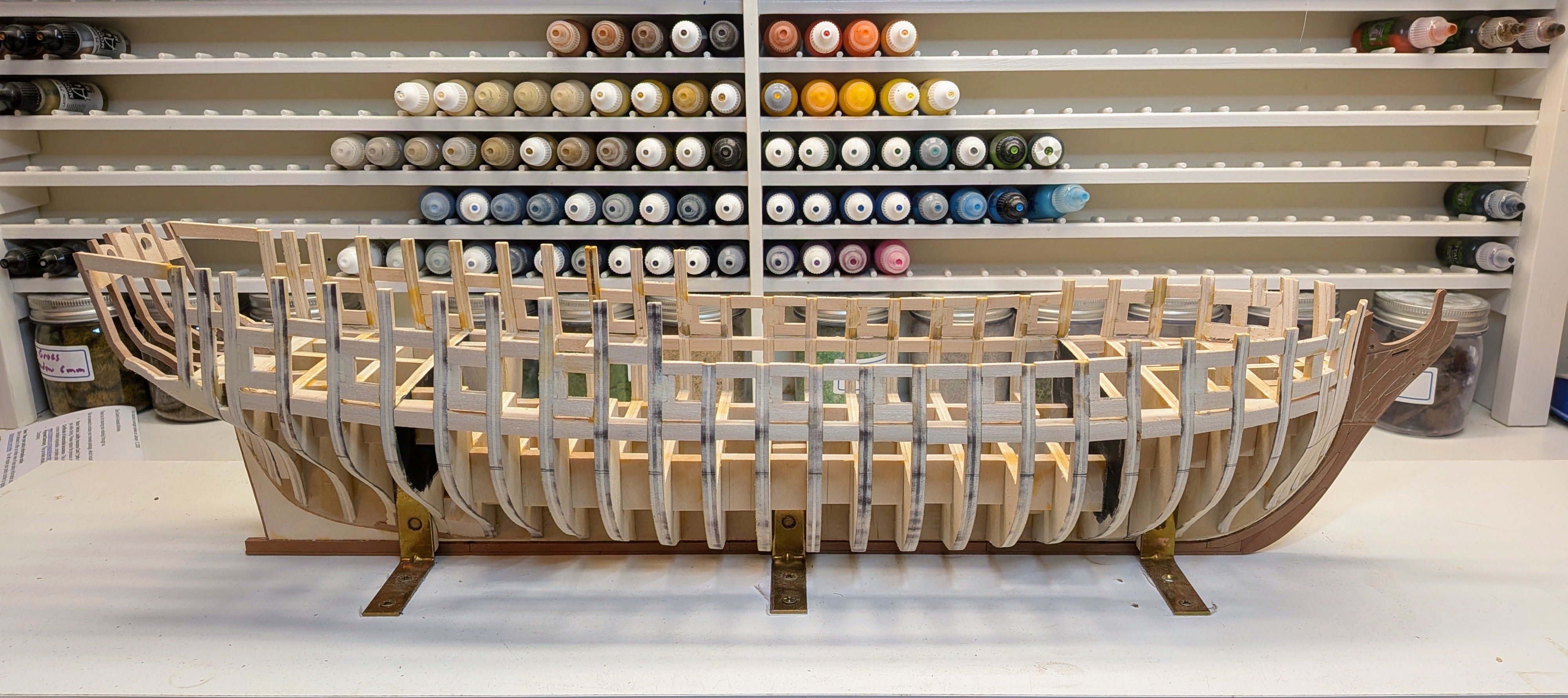
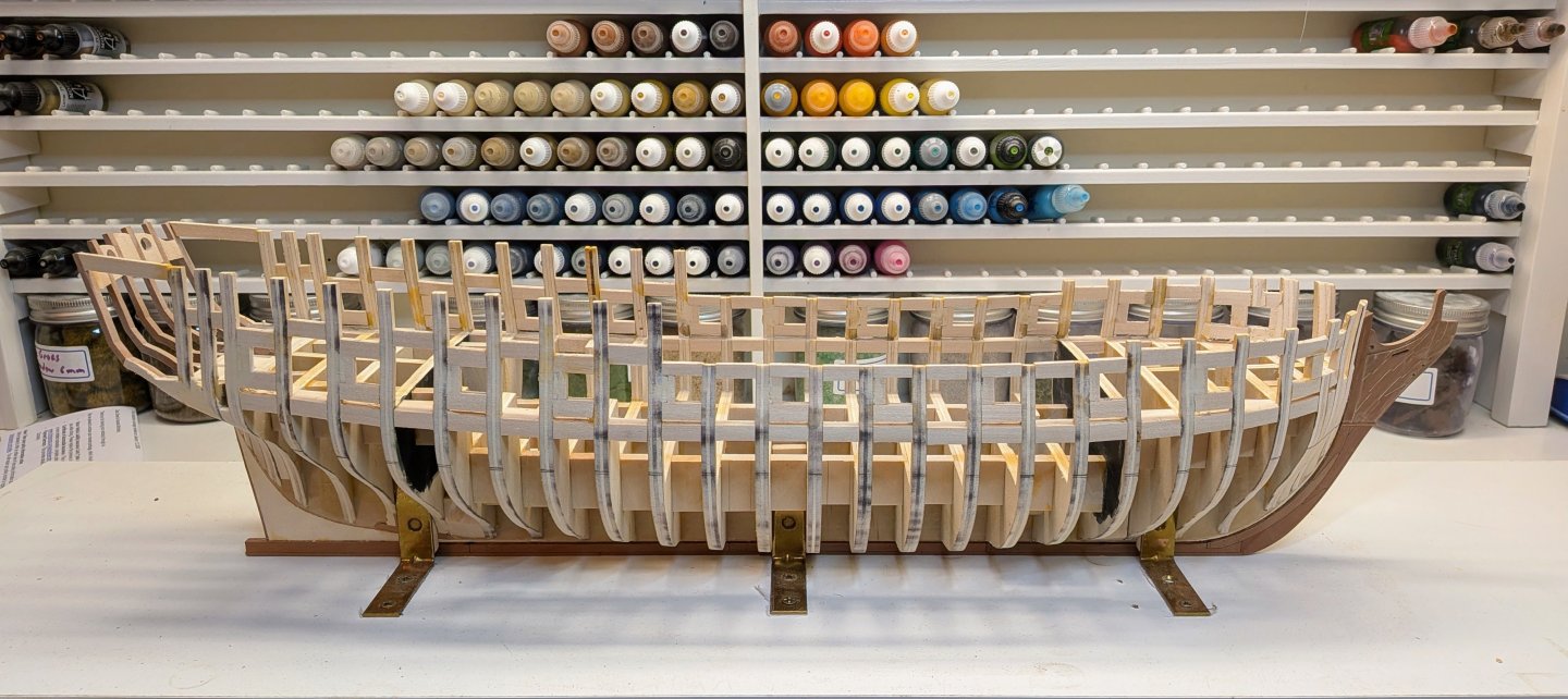
Log #32: Research Document Draft 2 I had not realized how long it has been since I last updated this build. The short explanation is that life has been really busy and so I have not had the time or energy to devote to the build. Little has changed since the last update, though I did finish the outboard faring and so removed the protective masking tape from the keel and bow to allow me to see the current state of Perseus better. Once you get in a rut of no progress it is hard to get going again and I am hoping I will be able to have more actual progress to report in the new year. Despite the lack of progress on the building front, I have made some progress on the research side of things. In particular, I have recently (as a way of encouraging myself to get rolling again), been working on cleaning up the research document to enable me to publish an update. The update contains the following changes from the previous version: The addition of the first part of chapter 3 detailing my research into the knee of the head and the figurehead of Perseus. Additional transcribed primary source material (mostly ordnance related) in the Appendixes. Numerous additions and changes to chapters 1-2 with more primary source material. A number of fixes and corrections. As with the previous document please feel free to reach out if you have any corrections / would like to offer some counterpoints to my conclusions. HM 20-Gun Ship Perseus C1-3 v0.2.pdf
-
USS Constitution by mtbediz - 1:76
Thukydides replied to mtbediz's topic in - Build logs for subjects built 1751 - 1800
Fantastic work, she she is looking really good. -
It looks much better, and I suspect as I have found to be the case, the difference is both more subtle and yet more impactful in real life than it appears in the photos. Great job!
-
Great job both on the painting and modelling of the stern. You can definitely see the improvement over the various versions. Lots of nice contrast there.
- 142 replies
-
- 4
-
-

-
- Christiania
- Vanguard Models
- (and 1 more)
-
I would recommend looking at a bunch of build logs. Find a method you like the results of and you think makes sense for you. Jigs are your friend here. Figure out the method and build a jig to allow you to replicate it. You can even try a few different methods to find out which one works best for you. Once you have one you like you can set up your jigs to reproduce it for all the guns. In terms of the rigging itself I personally only rig the side tackles and ignore the training tackle. Take a look at various examples to see what you like the look of best. Some prefer to only rig the breechings. It all depends on what you want to depict with your model.
-
Super cool that you are willing to share this with everyone. Great job.
-
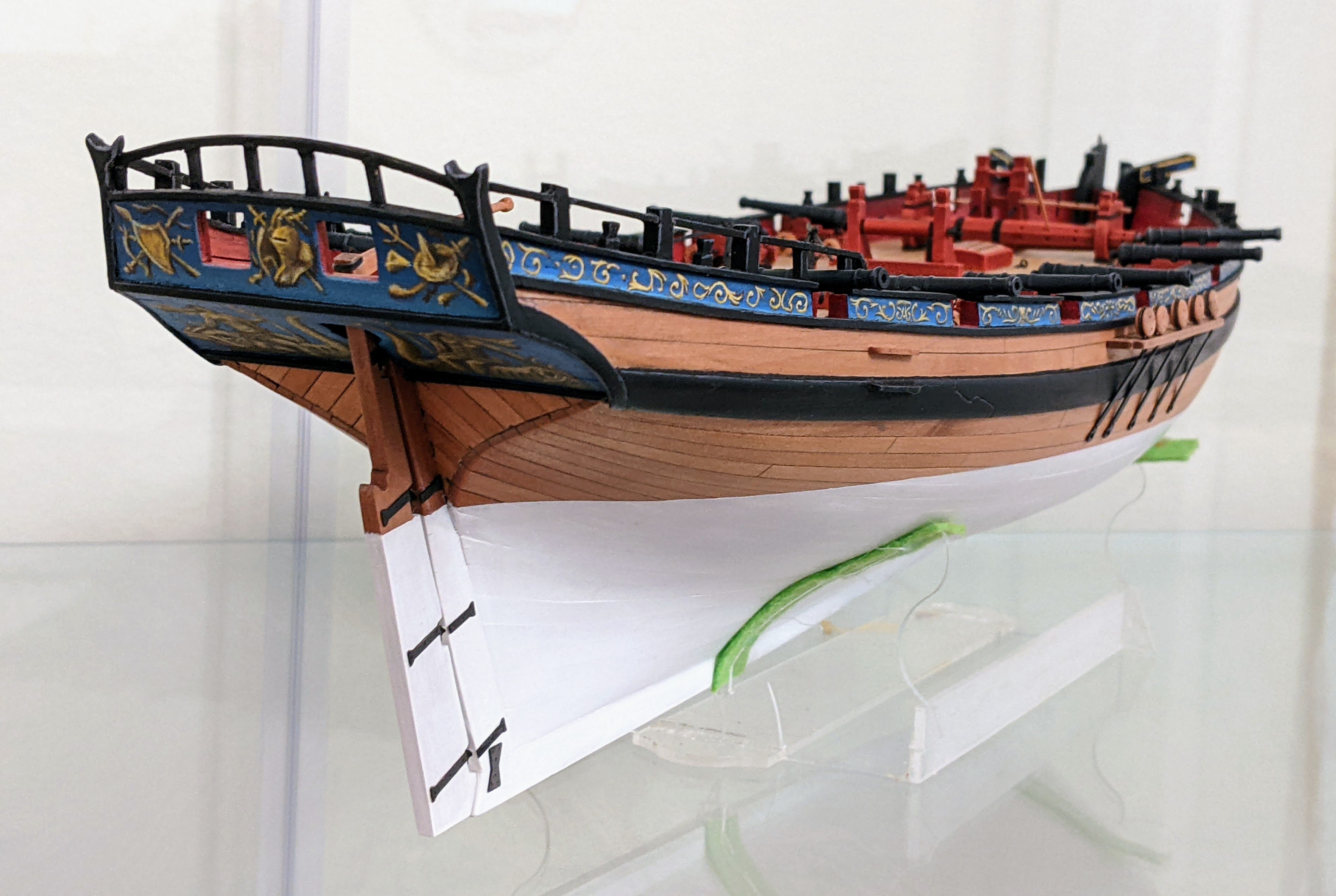
I will send you a link to the presentation vi PM. I think the colour you chose was fine, my point was simply that given the issues noted, I am not confident that your methodology has produced a definitive result. In terms of resources, I would actually say miniature painting tutorials are useful as long as you are looking at similar scales and styles to what you want to achieve. Most miniatures are at about 1/56 (many scale models are at 1/76) scale which is not too far off your scale so many of the techniques would apply. That being said if you are looking for a more realistic look then I would look at scale modelers not general miniature painters. Most miniature painting tends to be more stylistic in nature (which is fine if you want that sort of look). If you look at my alert model you can see how this might look on a model. I painted my alert to depict her as if she was in a painting so it has a very stylized saturated look. You could use many of the same techniques just mute the contrast a little and use less saturated colours if you want a more realistic look. If you have limited painting experience then I would probably limit myself just look into adding some edge highlights and maybe use selective application of a wash in the recesses and upper side of the port to push them more into shadow. This of course is based on my personal stylistic views. At the end of the day the question is really what do you want to achieve. Edit: I will also add the viewing distance matters. Do you want it to look good from 1 foot away or 5 feet away. The further away the desired viewing distance the more you should push the contrast. The closer you are the more important it is to have smooth transitions.