BETAQDAVE
-
Posts
5,386 -
Joined
-
Last visited
Content Type
Profiles
Forums
Gallery
Events
Everything posted by BETAQDAVE
-
 I am now at the point of painting the plastic hull of my Wanderer, and am in a bit of a quandary of how to proceed. I have used a technique promoted by Les Wilkins in his book How To Build Plastic Ship Models in the past with very good results. The technique was to first spray paint the masked hull with Floquil Copper. While this coat of copper paint is still fresh, you take a medium paint brush and apply Floquil Light Green paint with random vertical strokes, always brushing away from the waterline. Then using a clean medium paint brush this process is repeated using Floquil Antique White. Now with a clean brush frequently dipped in turpentine (Not lacquer thinner because it will eat right through the copper paint!) lightly brush with vertical strokes (again away from the waterline) over the green and white paints while they are still wet to make these two colors meld with the copper. Also, don’t brush too hard or you can rub through the copper paint and the turpentine can harm the plastic. The next step is to use a string or wire to suspend the hull in midair to dry for 3 or 4 hours which will allow the turpentine to run down to the keel as it dries. After the turpentine has evaporated and the paints have dried, take a piece of No. 600 sand paper and lightly sand the full length of the hull with back and forth strokes until some of the paint has been rubbed off the edges of the plates to make them somewhat more pronounced. The last step is to take a clean damp rag and wipe off the resulting sanding residue from the hull. The only problem here is that Floquil paint was lacquer based and is no longer available. I am wondering if this technique can be done with the enamel or water based paints that are available now. I have two 3 oz. cans of Testors copper spray enamel to act as the base coat and since Testors paint is still readily available in green and white; could this technique be employed here with their enamel paint or maybe water base paint?
 -
I would agree with that assesment also. Another consideration that occurs to me is the fact that wood and metal do not expand or contract at the same rate when reacting to changes in heat or moisture which would more than likely raise hovoc with the edges of the mortices inviting the intrusion of even more moisture.
- 24 replies
-
- 2
-

-
- pivot gun tracks
- pivot gun
- (and 1 more)
-
You need to apply a wood filler like Minwax 21600000 high performance filler first. This particular brand is my favorite as it's ready for sanding in about half an hour. Then sand it down until you get it to your desired smoothness. Once done you can paint it and have the smooth finish you're looking for.
-
2021 CALENDARS ARE GOING FAST!!
BETAQDAVE replied to ferretmary1's topic in NAUTICAL RESEARCH GUILD - News & Information
I'm in. -
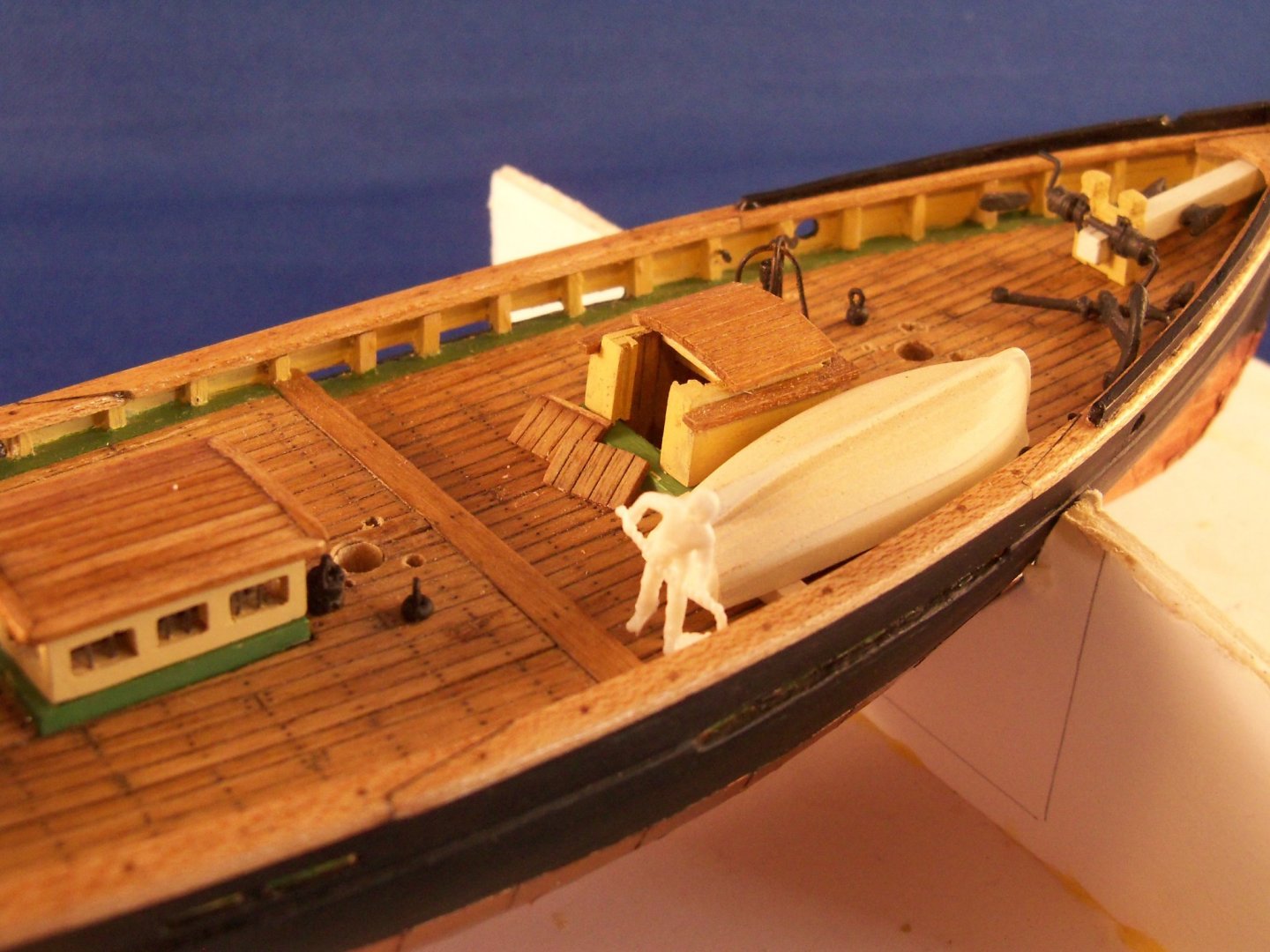
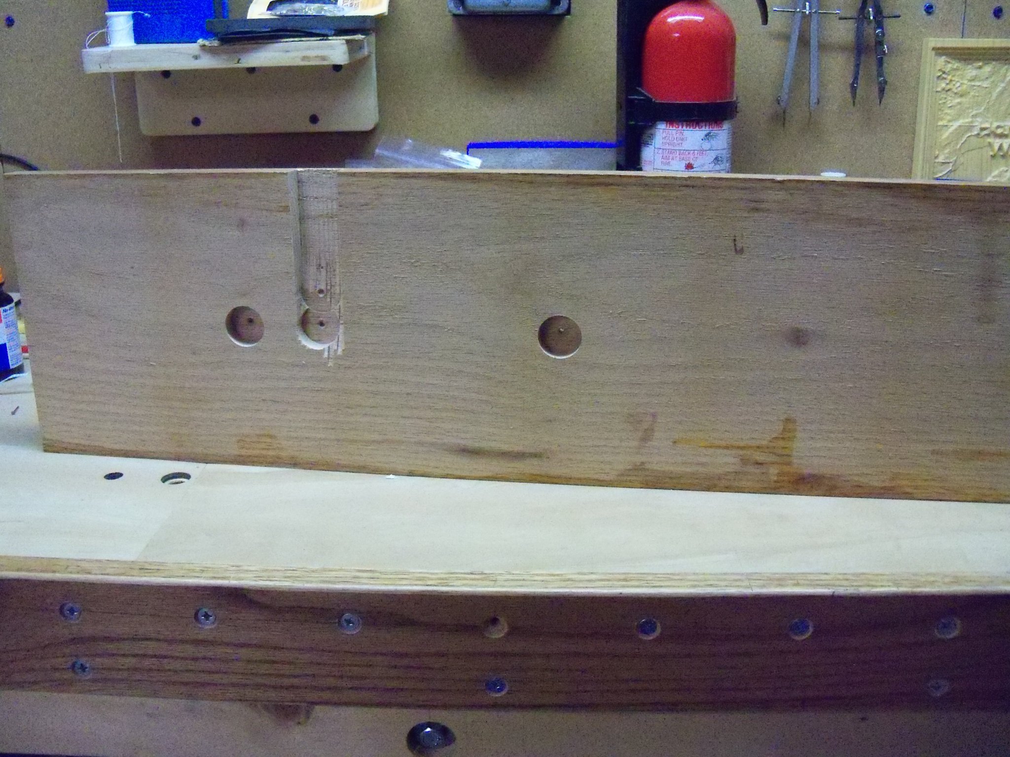
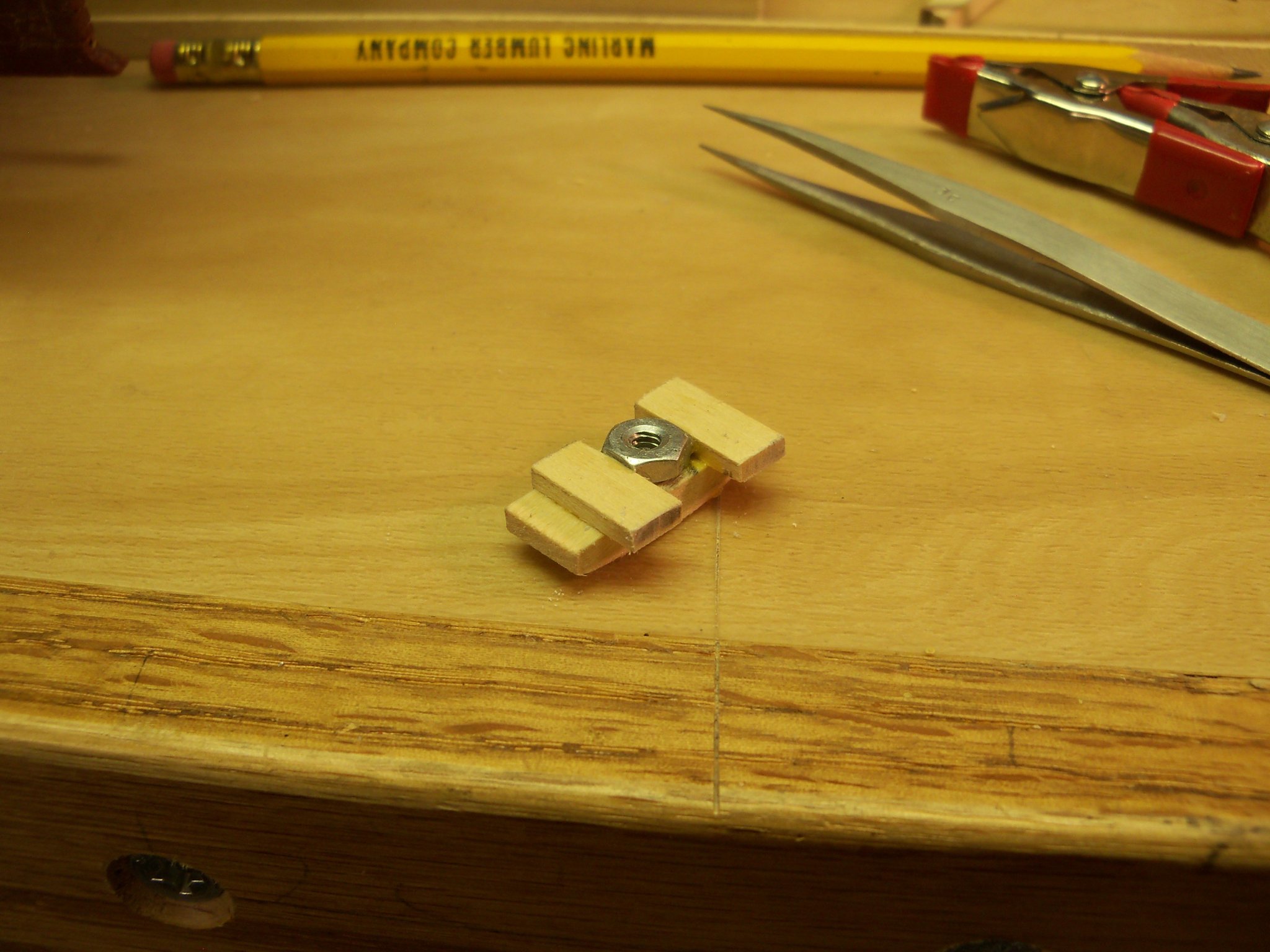
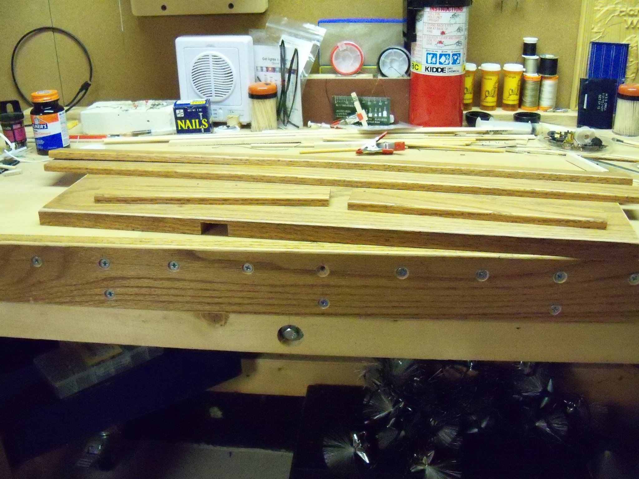
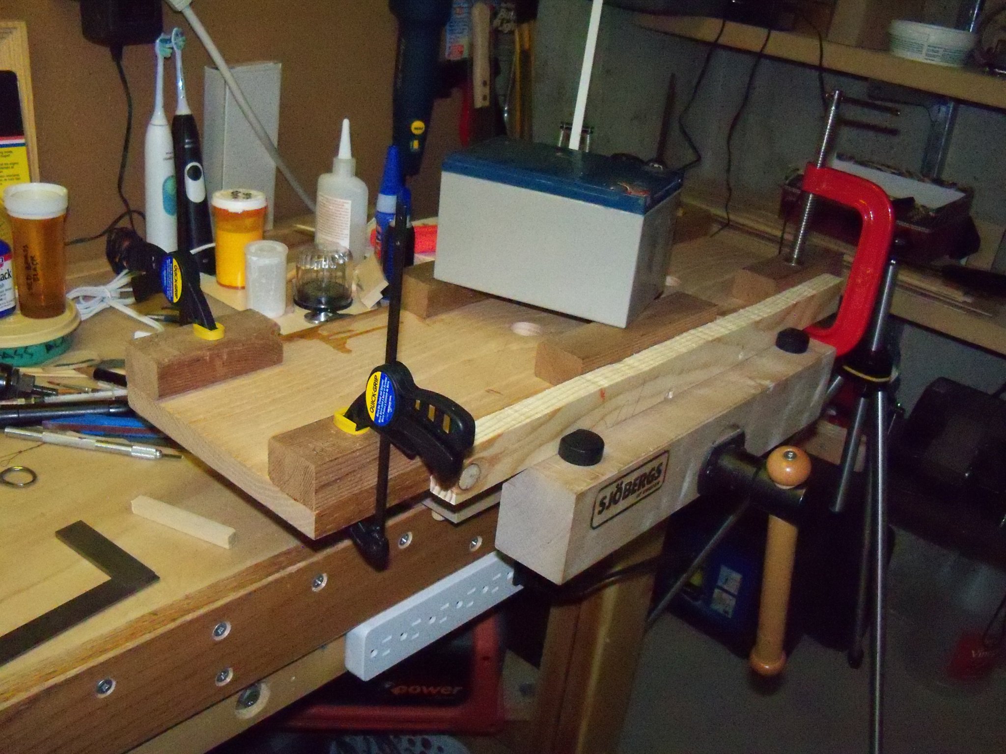
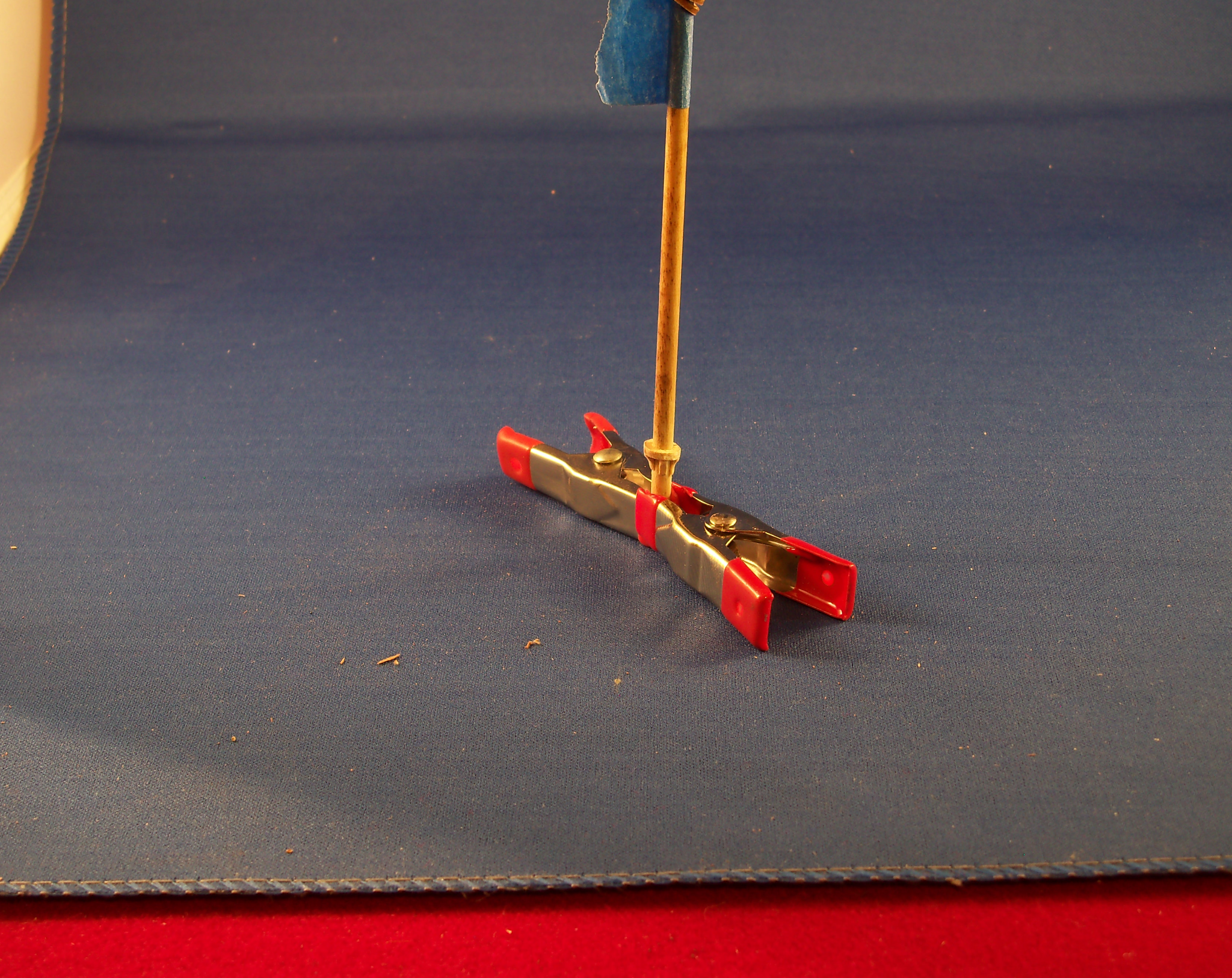
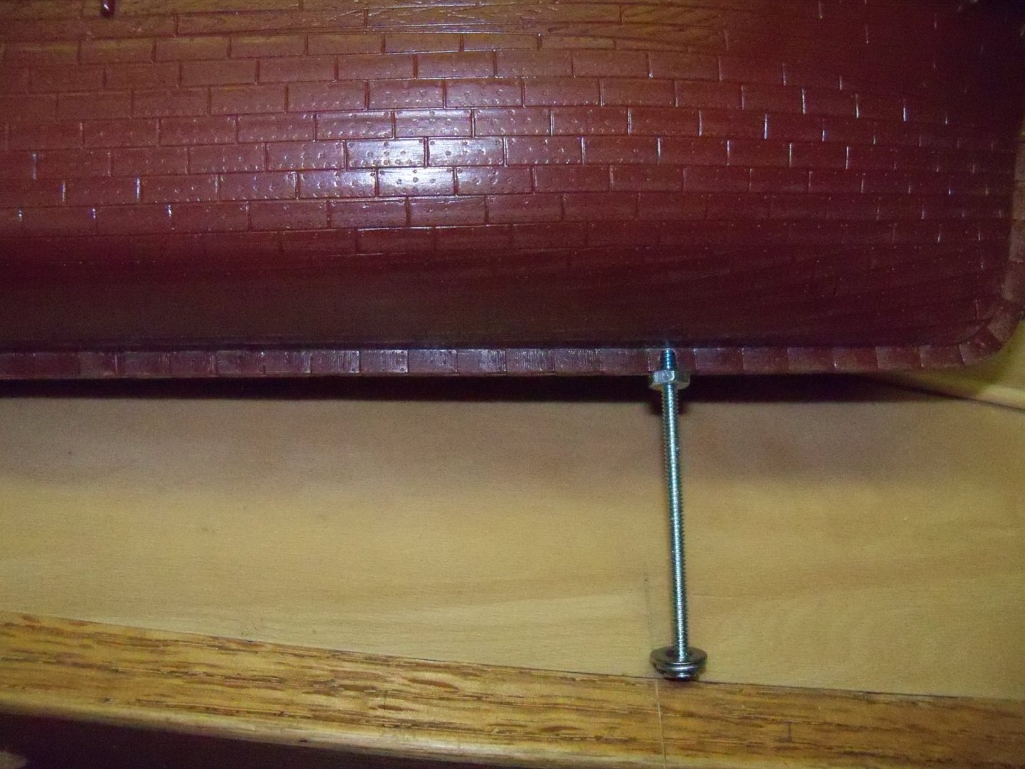
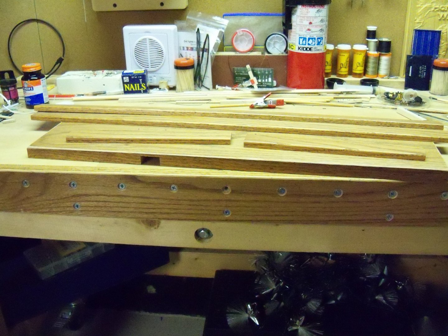
Finally, after a rather extended time away from this build and its log for a long list of reasons including work on my Phantom build log and waiting to remove the bed frame that blocked my access to my saws, I returned to working on this display base. The 1 x 10 oak base board was trimmed to its final length, the top edges were eased (slightly rounded over) and then lightly sanded. I positioned the launching ways on the base board and using a 7/64” drill bit through the predrilled mounting holes, I gave it a light tap to mark the locations of these holes on the base board. Since I had finally determined that I needed to use 1/8” bolts now for mounting the ship, all of the predrilled holes needed to be enlarged. I started by carefully enlarging the holes in the ships’ hull with a 1/8” drill bit mounted in my battery powered screwdriver/drill once again to avoid overdoing it. Once the holes in the hull were enlarged, I used my drill press to enlarge the holes in the launching way blocks. I drilled all of the 1/8” holes through the base board, and to reduce the length of the mounting screws, I used a Forstner bit to counter bore the holes about 1/2” deep on the bottom side. With the radial arm saw, a recess for the battery and switch was cut through the front edge and into the bottom. Then I used chisels to finish carving out the bottom of the recess. This was the bottom of the base board at this point. Then, just to be sure everything was properly aligned, I test fit the entire assembly to avoid the dreaded “Maybe I should have done things differently” syndrome later. (Its happened before!!) Now I made some hardwood blocks to glue inside the hull to mount some captured nuts for the bolts to screw into when the ship is finally mounted. The block for the stern bolt was the easiest since the inside of the hull was nearly flat there. The block for the bow end however, had to be shaped on the bottom side to match the curve of the inside of the hull at that point. The holes in the blocks were drilled one bit size larger than the bolts since their function is just to act as wooden washers that can be glued inside the hull. The bolts were inserted through the holes in the blocks and the nuts were then threaded down flush to the blocks. To “capture” the nuts, I simply glued some wood scraps with a heavy coat of wood glue up against opposing flats of the hex nuts to keep them from rotating when the screws are tightened. (A square nut would no doubt have been easier, but I didn’t have any on hand.) The scraps were clamped and set aside overnight to dry. Here are photos of the bow block after the clamps were removed. It was a bit tricky working the blocks into place with all of the deck beams in the way! (I could have used more than two hands, but of course there wouldn’t have been any room for them.) You can see below that the block in the bow was also very close to the heel of the foremast so it was made narrower than the stern block with the two wood scraps extended around the mast. I threaded an extra nut on the bolts well down from the end and inserted the bolts through the keel and then threaded the bolt through the captured nut on the block. Once this was done that extra nut below was used to pull the blocks up tight against the inside surface of the hull for gluing. After the bolts were tightened, I applied a heavy dose of plastic cement with a long wood skewer where the blocks met the hull. Once this cement hardened I added some medium CA to help secure them (since I was not sure how well the plastic cement would bond with the wood) and set the ship aside overnight for it to set. Now that this was finished, the hull was carefully masked with painters’ tape and paper towels to prepare for spraying the copper sheathing with my brand new homemade spray booth! Here you can see that the tape was purposely set about 1/16” back from the copper line as the black foil tape “planks” will cover the gap. So, here is the model itself as it stands now. Getting back to the base board once again, I combed through my “modest” scrap wood pile in the garage. I was able to dig out this 3/8” x 1 1/4” eased edge oak door stop for the moldings to go around the base and form a lip for the 1/4” Plexiglas cover to rest on. My first thought was to rip it down to ½” width and set the bottom edge flush with the bottom of the base, but after a trial fit, I really didn’t like the way it looked and I also realized that the Plexiglas really needed a little more overlap. So, I decided to use it as is and add some 5/4” thick scrap cedar furring blocks to the bottom along the edges of the base. That would leave the top of the trim 1/2” below the top surface of the base leaving a wider ledge to support the 3/8” Plexiglas cover. However, this presented another problem. The ½” deep chiseled out notch for the switch would now be exposed on the front edge! (Remember that dreaded “Maybe I should have done things differently” syndrome that I recently mentioned?) Oh well, it’s not as if it’s the first time that I had to go “back to the drawing board”. (It probably won’t be the last either.) At least now I won’t have to carve out any more recesses for the light wiring since the whole area below the base board would now be open. I carved the notch in the edge a little larger and cut an oak plug to fill the resulting gap. The plug was glued and clamped in place along with six 5/4” cedar blocks. Since the edges of this trim are eased, I will also need to miter the corners rather than butt them. As a sort of added bonus, the furring blocks should also make attaching the trim easier, especially at the corners. The next job will be to apply the trim to the base and figure out how I will actually install the battery and switch for the lights.


-
Change Theme
BETAQDAVE replied to cog's topic in Using the MSW forum - **NO MODELING CONTENT IN THIS SUB-FORUM**
I had to agree with that comment, but I was able to follow the solution shown below to switch it back. The rest of the changes are appealing to me. -
Converting a Backyard Shed into a Model Workshop
BETAQDAVE replied to Hank's topic in Modeling tools and Workshop Equipment
I like your version of a wire grommet here. I think that golf is the activity that I miss the most since my MD advanced to the point of loosing the ability to walk. I am however, very glad that I spent as much time as I could doing it while I was still able to do so, especially the rounds of golf in Hawaii! 🏌️♂️ 😎 -
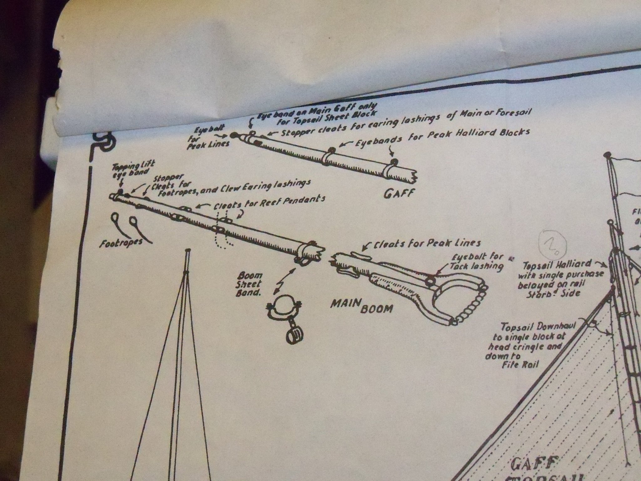
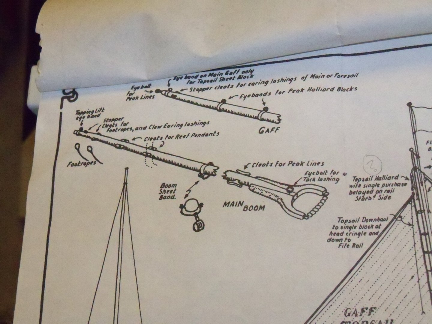
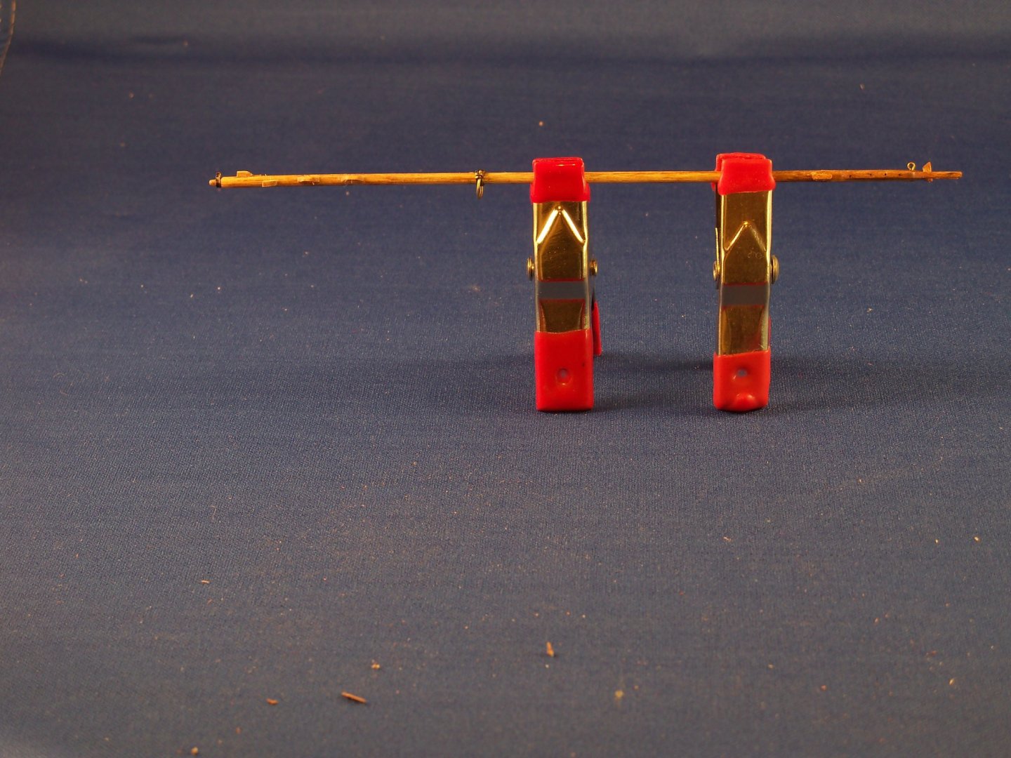
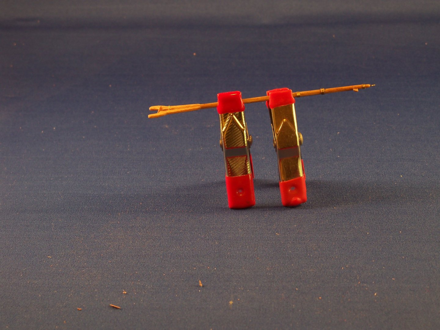
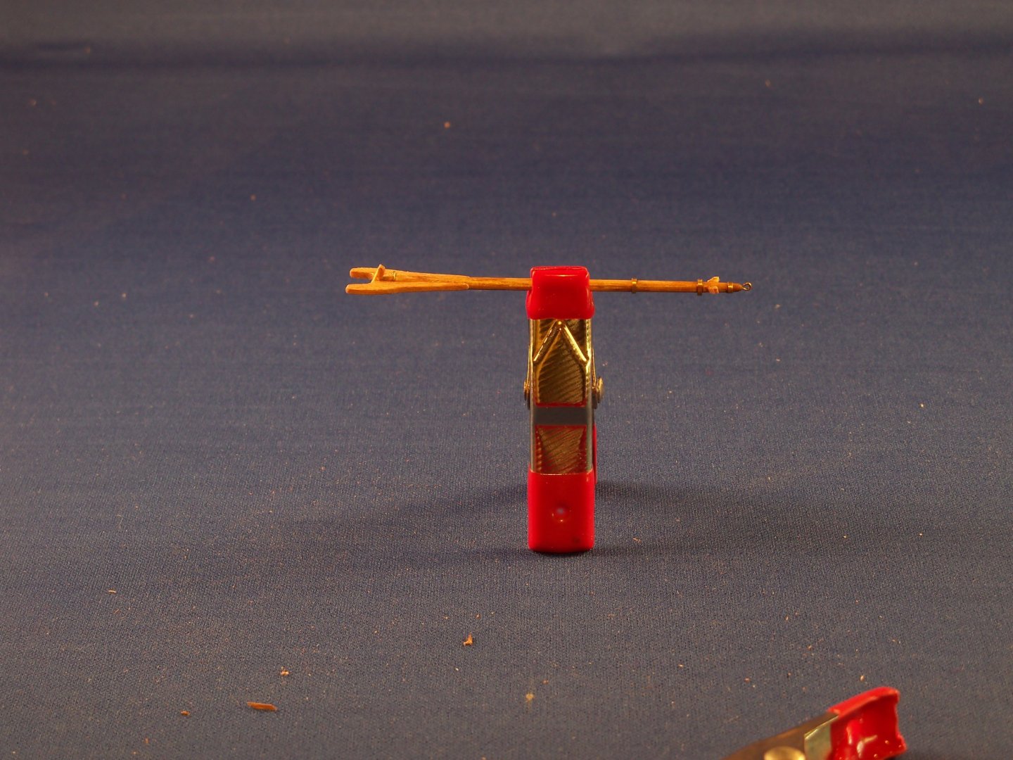
The plan detail that shows all of the main features of the main boom and the gaff ends is shown below. I tackled the main boom first. Taking the 1/8” kit dowel to the drill press, I tapered it at both ends. Once again the plans gave little information other than saying the maximum diameter should be about 1/3 of the way from the mast end of the boom with that also being slightly larger than the open end. The taper was supposed to be a parabolic curve, but of course at this small scale it will be hard to tell, so I just kind of eyeballed it and made it taper evenly. There was no plan view to show dimensions or the shape of the boom jaws, just the detail shown above. I looked at various drawings and photos of other schooners until I settled on kind of a compromise which turned out to be rather wing like, but were fairly easily fabricated from scraps of 1/16” maple. I filed the sides of the boom flat where the jaws would be attached and glued them in place with carpenters glue. After I gave it a couple of days to let the glue set up nice and solid, the jaws were filed and sanded in place. (I thought that would be easier than shaping them first since it also left me with a convenient handle.) Four impressions were made on each side of the jaws to indicate the bolts. When installing the eyebolt for the tack lashing, it was discovered that I had made an error by installing a bearing block which is only for the gaffs, not the boom! (Pay more attention to the drawings dummy!) So when I install the parral beads later I will remove it and install a filler piece. The two cleats for the peak lines were next. The cast metal cleats that came with the kit looked way too large to attach to the boom, so I took a 1/32” x 1/16” stick of maple and carved my own. It was easier than I thought, and with a little more practice, I could have done better, but making any of these 1/8” scale tiny fittings from wood can be very tedious and a bit frail. I think the trick is to basically shape as much as you can while you still have the rest of the stick to hang onto and then cut it loose for the final touches. After these were made and stained, I soaked the parts briefly in thin CA to strengthen it a bit, although these particular parts will not be under much stress on the model. Next up was the boom sheet band. I made the band from a narrow strip of shim brass that was annealed to soften it up a bit. Although the actual fitting was made from two separate pieces with a gap between them, the scale was too small for me to duplicate it that way. My method was to bend the band in half and pinch about 1/32” of the folded end tight in my vice. I opened the fold slightly and held a 1/8” drill bit on the resulting seam. I rolled the open ends of the shim back around the bit and pinched them to meet together opposite the fold held in the vice. I left enough of the shim ends exposed on the open end to set in a clamp and drilled holes in the resulting lugs for the 1/32” brass wire yolk. This wire was bent into a “U” shape to align with the holes in the lugs. I slipped the band into its final position on the boom and pinched the open end closed after giving it a touch of CA to glue it in place. The open end lug was then given a very small sliver of solder to hold it closed. The wire yolk was then set into the holes with just a bit left projecting through the holes. I applied a spot of solder on the exposed ends to serve as tightening nuts. Four short pieces of 1/32” maple were positioned near the end of the boom for the reef pendant cleats. They were set with wood glue and three more even shorter pieces were glued in place for the stopper cleats for footropes and clew earing lashings. Once these were solidly set in place their shapes were formed with files and holes were drilled into the reef pendant cleats. And finally a small band was fitted onto a shoulder filed on the very end of the boom for the topping lift. I made this band with a lug a little differently than the others by just pinching the band tightly around the shoulder. (I thought attaching a split ring here would be too large.) I gave it a touch of solder, filed down the end, drilled a hole in it for the lift and set in place with medium CA. The boom was stained with Minwax light oak and two light coats of satin finish polyethylene. The results of my labors on the main boom are shown in the two photos below, showing the different lug and my error on the jaws still to be repaired. The main and fore gaffs were very much alike except for their length so they were tackled together. The plan detail showed previously just showed the main gaff with a note concerning the two differences of an eye band and a gaff topsail sheet block on the main gaff only. Below are additional details on the jaw ends of the gaffs as shown on the plans. The gaffs were made from the 5/64” birch dowels that came with the kit. Before tapering the gaffs the first thing that I did here was to drill holes into the open ends for the peak line eye bolts. (Drilling a centered hole in the flat end of a 5/64” dowel, while not easy, was still easier than drilling it after tapering it thinner still!) They were shaped similar to the main boom with my drill press. The gaff jaws were assumed to be smaller, but since there were no dimensions given, I had to wing it. (The detail drawings are great for giving you a sense of the overall appearance, but not having been drawn to scale it forces you to make an educated guess for sizes.) So once again I filed down the flats for the jaws on the mast ends and glued some more of my 1/16” maple on them like I did for the boom. (This time I made allowances for the bearing blocks!!) These blocks were shaped from maple and glued in place at the angles indicated on the sail plan. I filed the jaws to shape and made the bolt impressions on their sides. One note here, when attaching the jaws to the boom and gaffs, I cut some custom tapered shims that I glued down to a flat scrap of wood to align and support the face of the jaws while the wood glue set. Both gaffs required an iron “U” bolt close to the bearing blocks to hook the throat halliard blocks to. For these I bent a piece of 1/32” brass wire to shape, drilled holes in the ends of the gaffs and these were glued with some medium CA. Also required, was an eyebolt attached to the bottom side of the main gaff only, for attaching the gaff topsail sheet block. Two eyebands were needed on each gaff for the peak halliard blocks, so I cut those bands and glued them in place with CA. The main gaff also needed an additional eyeband near the open end for a topsail sheet block which was filed with a very slight shoulder for it. I will later solder small brass split rings to all four of these remaining bands before attaching the blocks and attaching the parral beads. I shortened the eyebolts for the ends of the gaffs and glued them with a touch of medium CA. Both gaffs were fitted with a pair of tiny maple stopper cleats for the earing lashings of the main and foresails which were once again filed to shape after being glued into place with wood glue. The gaffs were also stained with Minwax light oak and two light coats of satin finish polyethylene. The following photos show the results of my labors on the gaffs. While there still remain some details to finish (or correct) on both the masts and spars, I will take care of them on a later posting.


-
Connecting Pins - Need help on first build
BETAQDAVE replied to Brianh526's topic in Metal Work, Soldering and Metal Fittings
And hopefully the brass wire will melt before your fitting does. The "Amnesia" black monofilament (fishing) line method sounds safer to me since it has a much lower melting point and doesn't need to be blackened. -
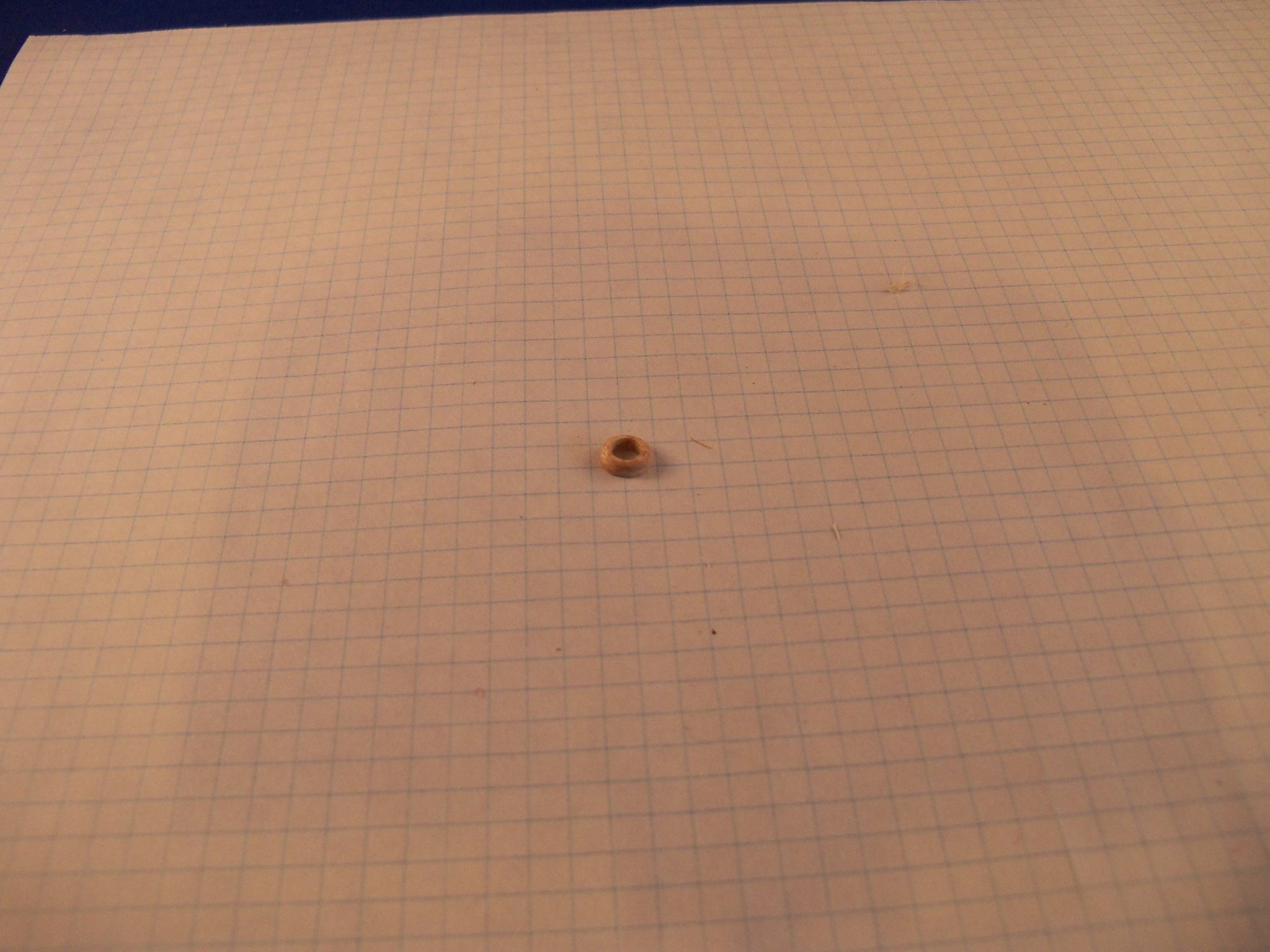
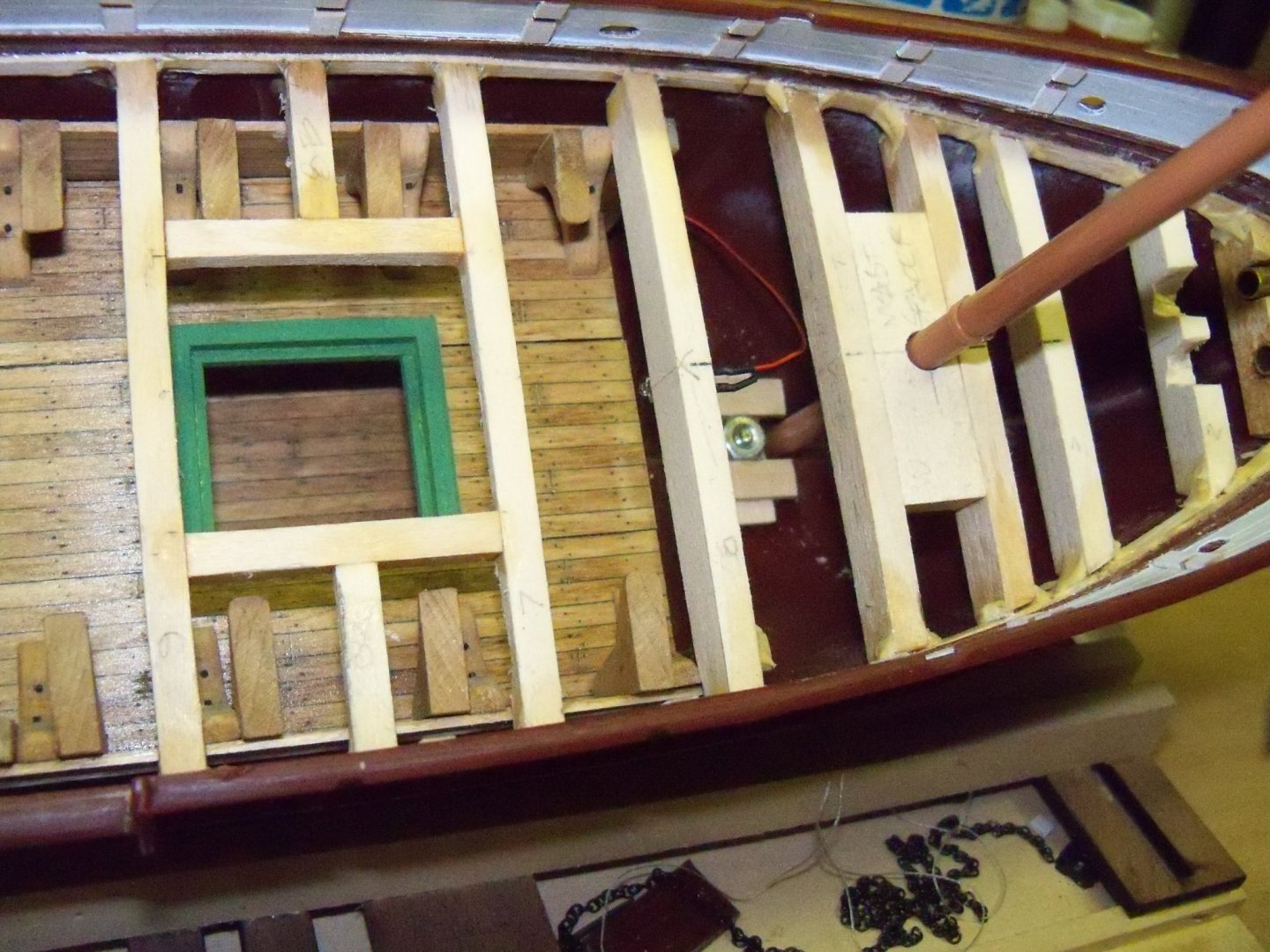
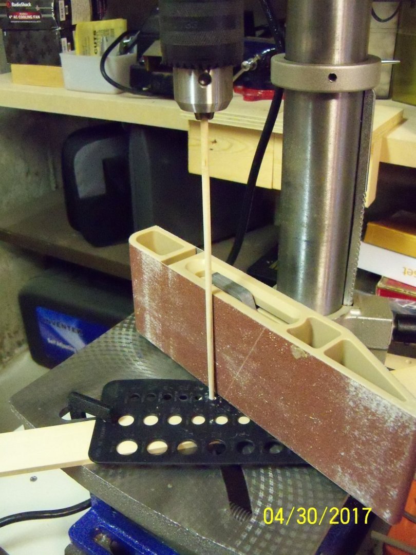
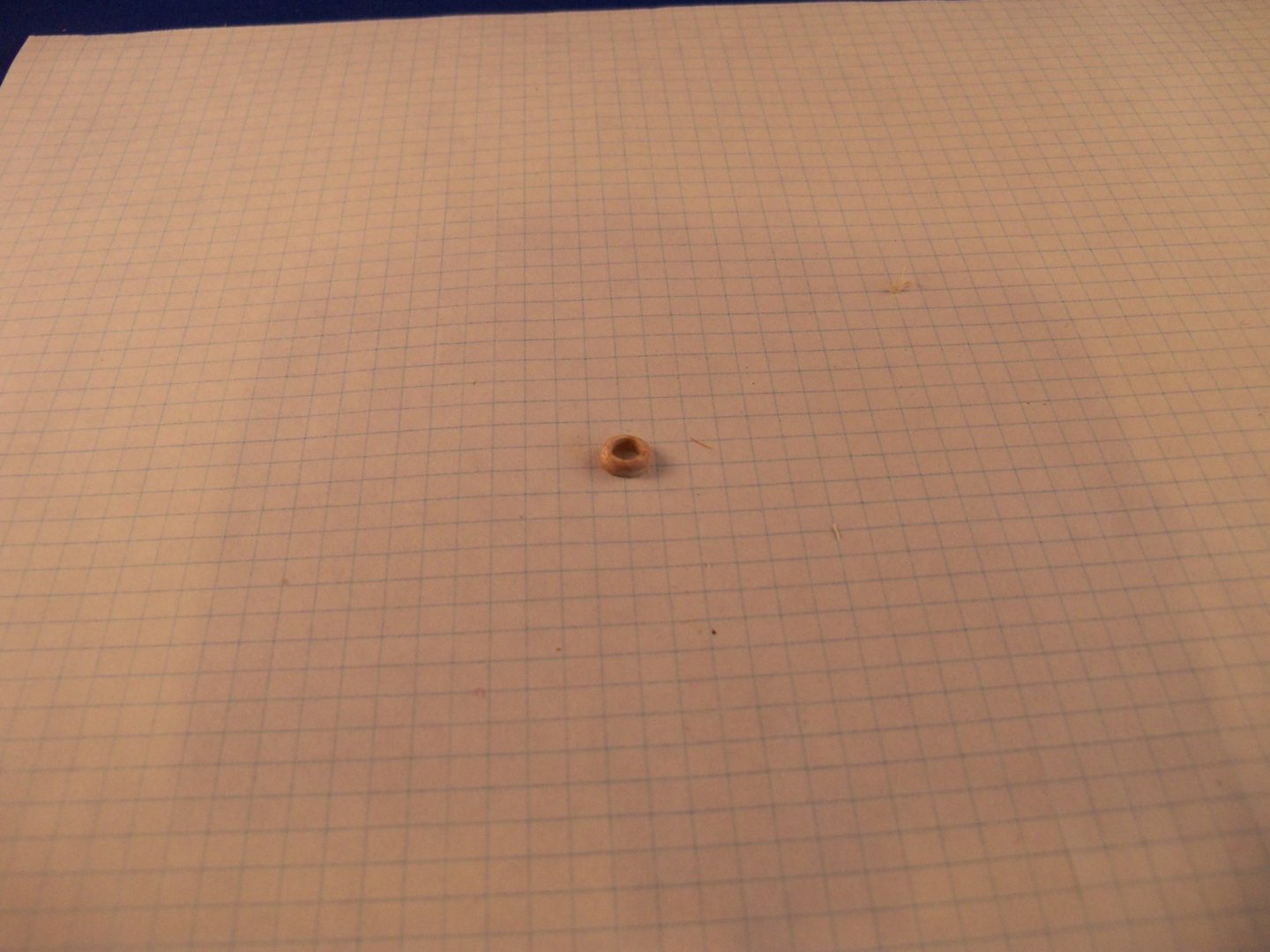
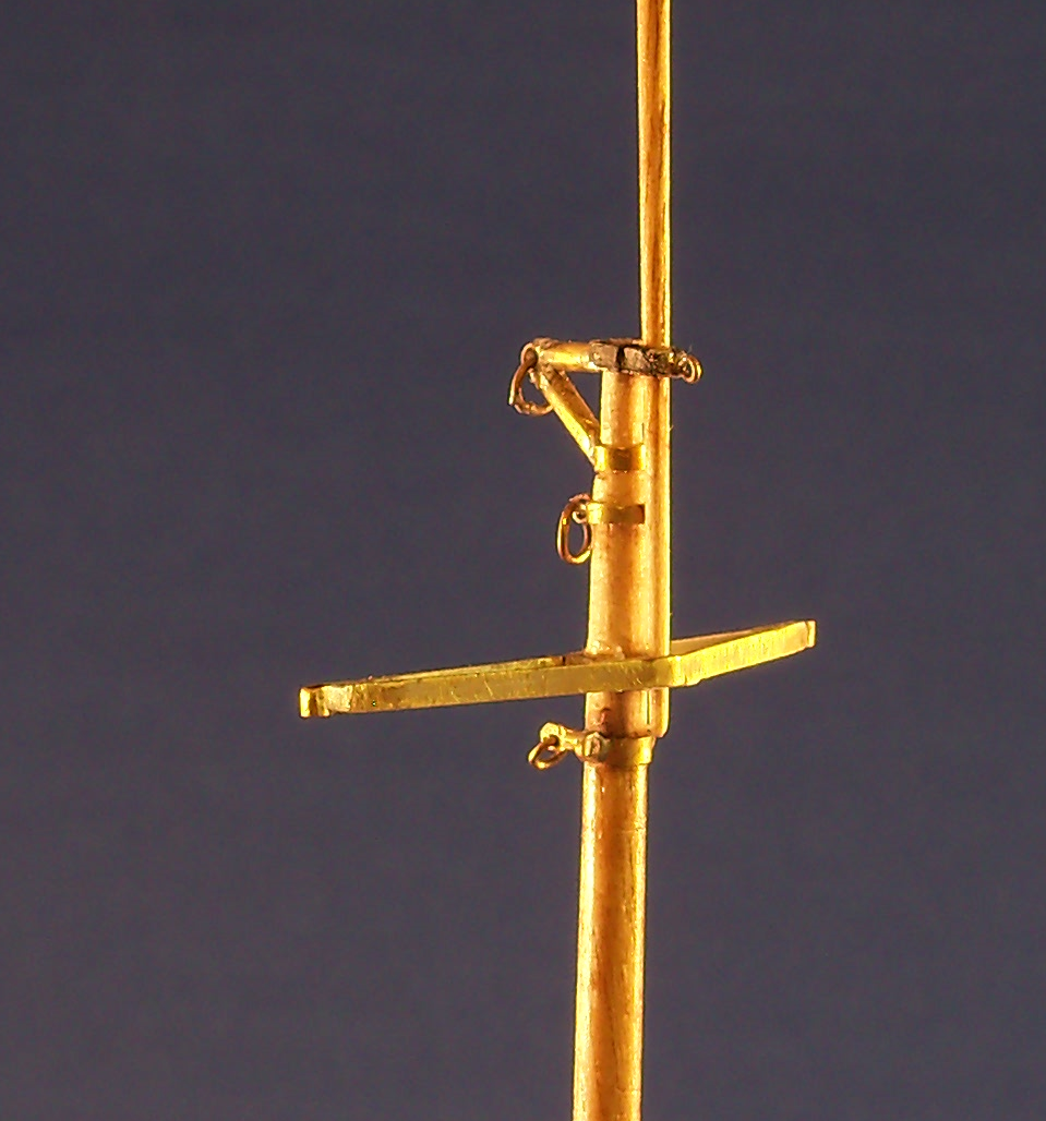
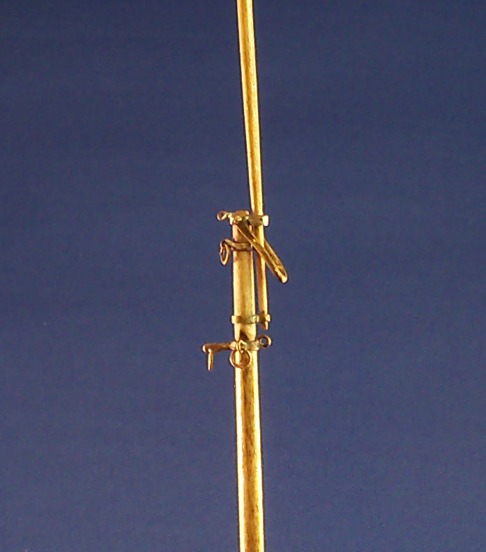
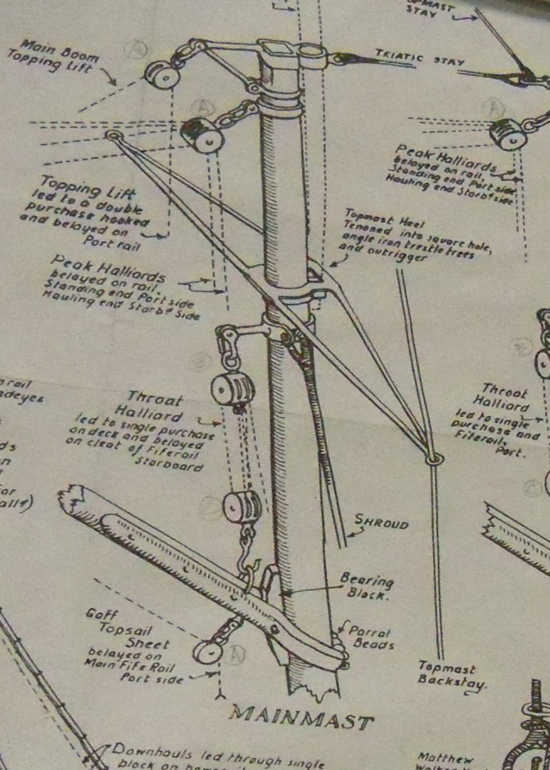
Shifting gears once again, I turned to making the masts. I started by tapering the masts. The photo below shows my set-up for tapering the foremast from a 5/32” dowel that came with the kit. The first order of business was to bottom out the dowel in the hole previously bored into the hull. I ran a pencil around the bottom of the mast at the deck, removed it from the hole, measured the height of the mast off of the drawings, marked the top of the dowel and added 1/8” to it. The dowel was then cut off at this mark. I inserted the portion of the mast that would be below the deck into the drill chuck. To steady the dowels other end, the remaining 1/8” of it was set into the 5/32” hole in a drill index with a scrap of wood to back it up. This was then clamped in place to the table. Using a sanding block with #180 grit sandpaper and the drill press set at medium speed, the block was held at the bottom of the dowel until the top end of the mast matched the diameter on the plans. I used my digital calipers to check my progress. Since the kit instructions did not indicate exactly what kind of shape the taper was to take on and the plans only showed a straight even taper, that is how I shaped it. I used a straight edge held against the dowel to keep track of my progress and just continued running the block up and down the whole length of the exposed dowel until I had a smooth even taper. Once I had it shaped to my satisfaction, the dowel was removed, cut to its final length and the very top was filed square until it fit into the metal mast cap fitting. All the masts, gaffs and the main boom were shaped similarly. The mast coat was next. This seemed daunting at first as you need to basically form a doughnut from wood. It actually turned out to be fairly simple. Taking a 3/8” square basswood timber, I sliced a piece off of the end of it the height of the mast coat. This piece was glued onto a piece of paper and left to set. When dry, it was clamped in a vice and I drilled a 5/32” hole through the center of this piece. A short piece of the 5/32” dowel was inserted into this hole to serve as a handle and temporary reinforcement. Since this left the end grain of this block exposed, it was a simple matter to split off small slivers of wood with a sharp razor blade until I was left with a wooden ring the diameter of the mast coat. The remaining ring was given a coat of poly to seal it after I had sanded it into its final shape. The paper was peeled off of the bottom leaving a nice wooden mast coat as shown below to be set aside until the mast could be mounted to the deck. I took a short break from making the masts to make up the two sizes of mast hoops from used paper grocery bags. I took lengths of appropriate sized wood dowels and wrapped them with wax paper. I cut strips of paper from the bags and wrapped them tightly several turns around the mast hoop forms after giving the strips a thin coating of wood glue on one side. These were then clamped and set aside for a couple of days to thoroughly dry. Taking the clamps off, I rolled a razor blade over the forms to separate the individual hoops. (I made sure to make plenty of extras.) The resulting hoops were soaked briefly in Minwax light oak stain. After these were dried again, I soaked them in diluted poly to give them some added stiffness. The photo below is a detail from the plans showing the foremast details described in the following text. There were three mast bands plus the mast cap that needed to be formed for the upper end of the fore mast. The lowest band was done first. I used some thin walled brass telescoping tubing that I had on hand to make the bands. A short length of tubing with an inside diameter equal to the mast diameter at the location shown on the plan was sliced off and slipped into place on the mast and secured with CA. This band needed one lug to attach the forestay on the front face and a pair of lugs on the port and starboard sides to hold the double shrouds. I made small brass split rings that were soldered to the band to serve as lugs. This band also required a short bar extended from the back side of the band to attach the throat halliard block assembly. For this detail I took a short length of 1/16” solid brass bar and flattened one end on an anvil. This flat end was then shaped and drilled for a shackle. Then I soldered the other end of the bar to the band. I found out that the trickiest part here was just trying to solder a fitting on without unsoldering the ones you had already put on. The lower cap or yoke that holds the bottom end of the signal pole was done next. This was one of the simplest as all that was needed was to solder a band sized to insert the end of the 5/64” signal pole to the face of the band on the mast. The third mast band was also pretty straight forward since it only needed a single lug on the backside of the mast. All of these bands were slipped into place and glued with CA. Once the other bands were set in place I returned to the mast cap fitting. The back-side of the square cap needed a single lug, so I soldered a brass split ring to it. A peculiar fitting called out as a span iron on the plan detail was also needed. I sized a length of tempered 1/16” brass wire to match the plans and bent it around a round metal bar with a diameter that matched the outside width of the square portion of the mast cap. Taking the resulting “U” shaped bar to an anvil, I flattened, shaped the ends and drilled a 1/32” hole through both ends of the “U”. The mast cap was glued onto the square tenon of the foremast with CA. I drilled a 1/32” hole all the way through the square part of the mast cap and the mast to align with the holes in the span iron. A short section of 1/32” brass wire was cut with one end blunted to imitate a bolt head. This wire was passed through the assembly leaving a small projection exposed and given a small spot of solder to imitate the other end of the bolt. This allowed the span iron to freely move in place. The signal pole was cut from a slightly overlong piece of 5/64” dowel that was chucked into the drill press and shaped with a taper at both ends. At this point, I applied Minwax light oak stain to the foremast and the signal pole followed by two coats of satin finish polyethylene. The white portions of the masts will be painted later. The six brass split ring/shackles were all hung in place and soldered closed for later attachment of the rigging. At that time I will squeeze them all into more of an oval shape. My finished version of the foremast detail is shown below. The photo below is a detail from the plans showing the mainmast details described in the following text. There were four mast bands plus the mast cap that needed to be formed for the upper end of the mainmast. I started with the lowest band first that needed lugs to attach the shrouds to, so once again I soldered a small brass split ring to each side for that. This band also needed a short bar extended from the back side of the band for attachment of the throat halliard block assembly. This was handled the same as the short bar on the foremast. The next band was totally different from all the other bands since a topmast spreader was needed. The detail of this spreader on the plans, called for an angle iron trestle tree with outriggers to port and starboard. There are no cross sections to show if the outriggers are a continuation of this angle iron shape or just a flat iron bar welded to it (since I didn’t think that such a complex fitting could possibly have been formed from a single piece back then). The kit instructions called for a solid round metal bar bent into something of a narrow triangle shape, bent with integral holes formed on the ends for the backstays. In the end I decided to do things a bit different from either method. I used a short length of the brass tubing again for the band and then cut two narrow strips of shim brass that matched the length of the band. One piece was cut to the overall length of the spreader and the center of the spreader was soldered to the back side of the band. Taking two lengths of very small diameter brass tubing (just large enough for the backstay to pass through) cut to match the width of spreader bar, I soldered one of these to each end of the spreader. Another piece of brass tubing to match the diameter of the end of the topmast was soldered to the front side of the band. Then the other narrow strip of shim brass was given a slight bend in the middle that was soldered to the front side of the topmast band. The free ends of the strip were then cut to length and soldered to the brass tubing at the ends of the backside of the spreader. The next band up was a simple band with one lug on the backside of the mast. Another split ring was soldered on for the lug and a split ring/shackle was attached and soldered shut to finish this one. The final band was to serve as a diagonal brace for the extended stub on the backside of the mast cap above. I think that I may overbuilt this compared to the plan detail, but then I thought their version was rather weak for the heavy weight of the main boom that it needed to support, especially when in port as there was no boom rest. The band was formed and glued in place with CA. The top of the mainmast was squared off to fit the mast cap and this was also glued in place. A small split ring was soldered to the front of the mast cap for the triatic stay. On the backside of the cap, the extender bar itself was formed with a length of 1/16” round brass bar. Another piece of the bar was also used to make the diagonal brace. The brace was cut to length and shaped with files to fit snugly to the face of the band and the extender bar. The ends of the brace were then soldered to both the band and extender bar. The joined end of the extender bar was smoothed with files making a flat area on both sides of the joint. This flat was drilled through for the split ring/shackle which was then soldered shut for attachment of the main boom topping lift single block. (The kit supplied 3/32” block also seemed too small for the weight involved so I may substitute a larger one.) The topmast was tapered at both ends and given a shoulder near the top for holding the two backstays, the main topmast stay, and the gaff topsail halliard. The topmast was then slipped through the mast cap and the heel socket and glued with CA. I haven’t fitted a ball truck yet for the flag halliard, as I’m not sure how I will handle it. Here is a photo of my version of the band area of the mainmast below. The main boom rest was made similar to the mast coats, but with a slight slope to the top surface allowing it to be level with the deck surface by drilling the center hole at a slight angle. The rest was glued in place with wood glue and set aside to dry after taping the mast rings on the mast above. Six small scraps of basswood were equally spaced around the mainmast below the boom rest and glued with carpenters glue. Being such tiny pieces, I decided it was easier to file them into shape after gluing them on. This photo below shows my boom rest. As I did to the foremast and signal pole, I applied Minwax light oak stain to these also, followed by two coats of satin finish polyethylene. The white portions of these and the mast coats will be painted later. The mast coats can’t be glued in place until the fife rails are attached because they are wider than the opening in the rails. As far as the fife rails are concerned I may decide to make them from maple rather than the metal fittings that came with the kit. My next entry will be making the boom and gaffs.

-
Hello Doris. I hope you and yours are weathering this pandemic any better than we are over here. One can only pray that by opening things up again so soon over here with few guidelines to keep it under “control”, that we will not experience another wave that can easily get out of hand again. On a lighter note, I have a question on how you handle the “ironwork” on your models, such as the deadeye strops and chain plates as shown back on post #817. I know you work primarily with card, modeling clay and wood, but paper has its limits on items like those which are put under a lot of strain from the rigging. I personally have difficulty both with shaping and soldering metal components. Do you purchase those items from others, or do you make your own? I haven’t come across any of the techniques that you employ to handle such items in your logs and wonder how you handle them.
- 1,035 replies
-
- 4
-
-
- royal katherine
- ship of the line
- (and 1 more)
-
Converting a Backyard Shed into a Model Workshop
BETAQDAVE replied to Hank's topic in Modeling tools and Workshop Equipment
When learning drafting we were taught that while natural north light is the easiest on the eyes, for drafting it must be supplemented by artificial light due to its inconsistent nature. Direct sunlight should never fall on the drawing board because it is usually too intense and produces blind spots or highlights on either the paper or your instruments. Soft natural light from the upper left is the most effective for you if you are right-handed and vice versa if you are a lefty. Overhead fluorescent lighting is well-diffused when it falls on your drafting board and produces few shadows when properly installed. The light intensity should be somewhere between 60 and 100 footcandles on your drawing surface. One effective source of light would be one of those adjustable floating arm drafting lamps with two 15-watt straight fluorescent tubes in the reflector head with a base that can be clamped to the edge of your drawing board. Similar fixtures come with a single incandescent bulb or a combination of a 60 watt incandescent bulb in the center of the fixture with a round fluorescent bulb surrounding it. Some of these fixtures even have illuminated magnifiers attached to them which would be a great advantage for doing very detailed work on our modeling projects especially for those of us with failing eyesight. If you use the fixture with two straight fluorescent bulbs, having one daylight bulb in combination with a white bulb would give the best results. One caution with fluorescent bulbs is that they produce a stroboscopic effect when shiney tools are used under this light. This can be annoying, but can be reduced by using a light with a higher wattage or by using a combination of fluorescent and incandescent bulbs. I am not familiar with effects that the newer LED bulbs would have, but as long as confusing shadows are eliminated and the light intensity is sufficient you should be happy with the results. -
Welcome aboard! Building a model of something that you have some connection to really helps to maintain your interest. I have the same urge to build a 3/16" scale scratch model of the Wisconsin schooner Denis Sullivan. I have been aboard her, have taken numerous photos and even got some detail drawings from the architect, but I have been searching unsuccessfully for the hull drawings for years. Better luck for you on your search.
-
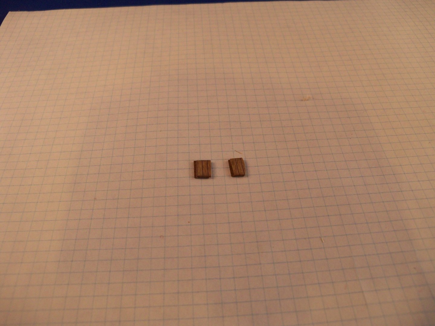
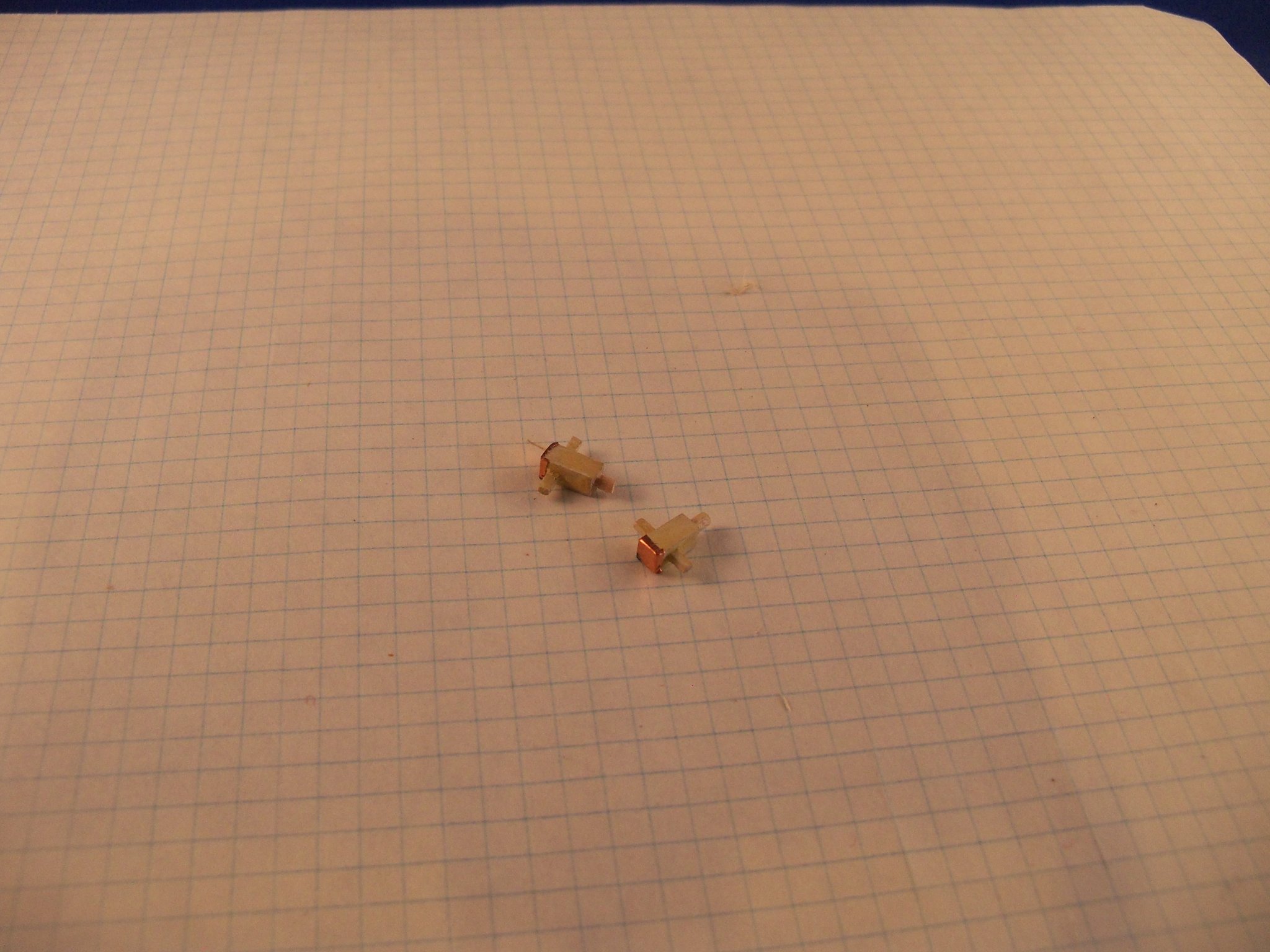
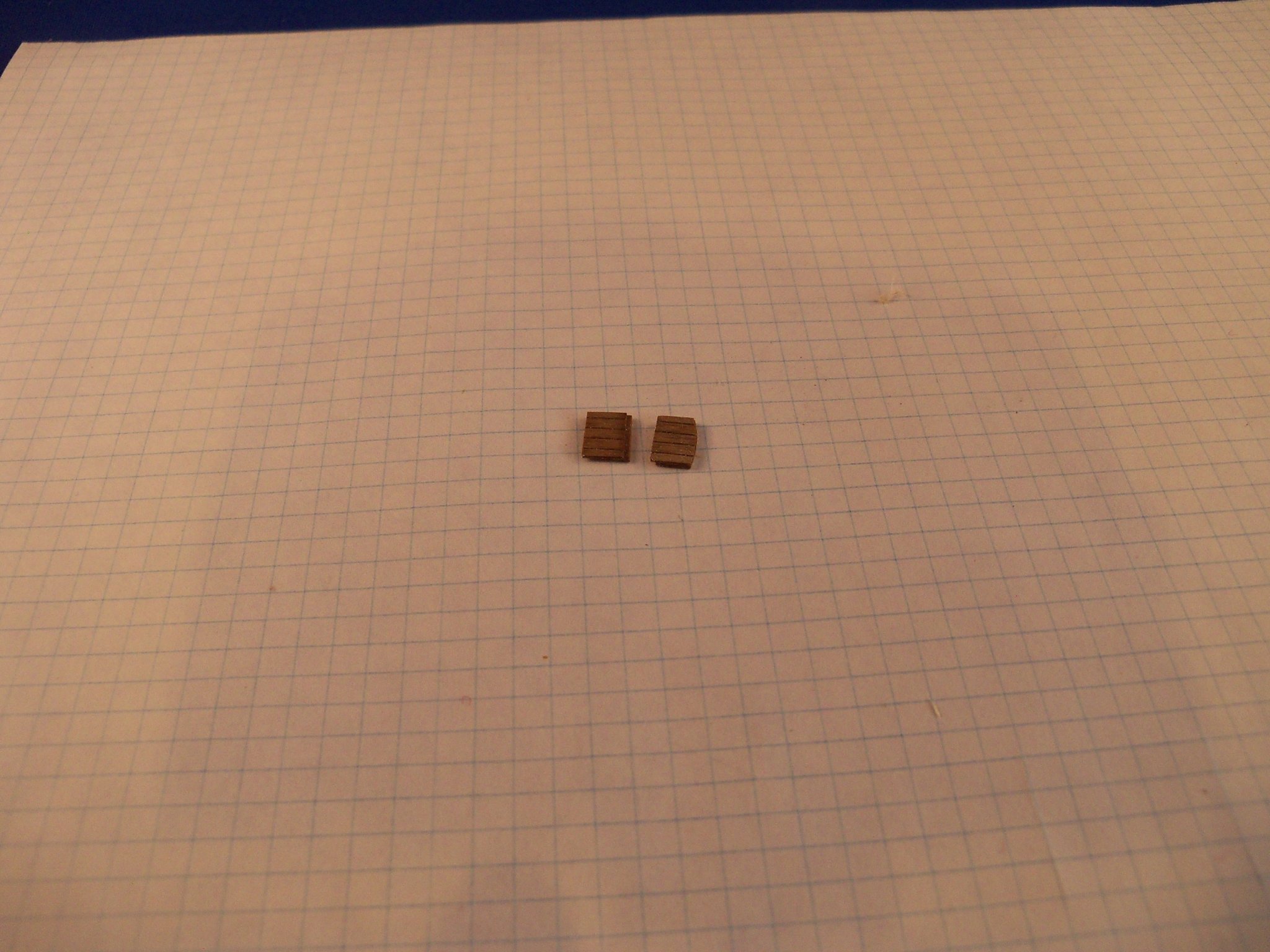
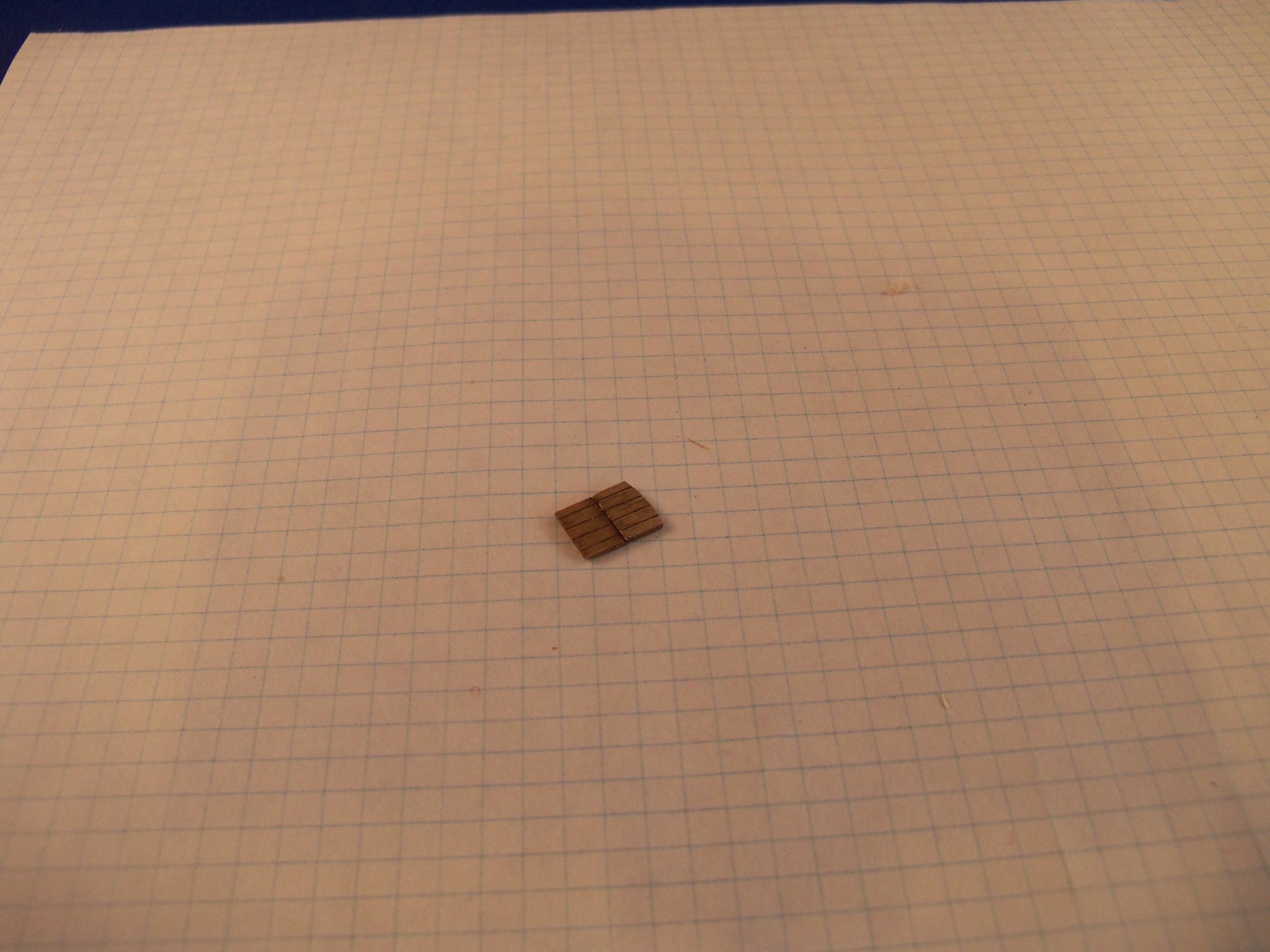
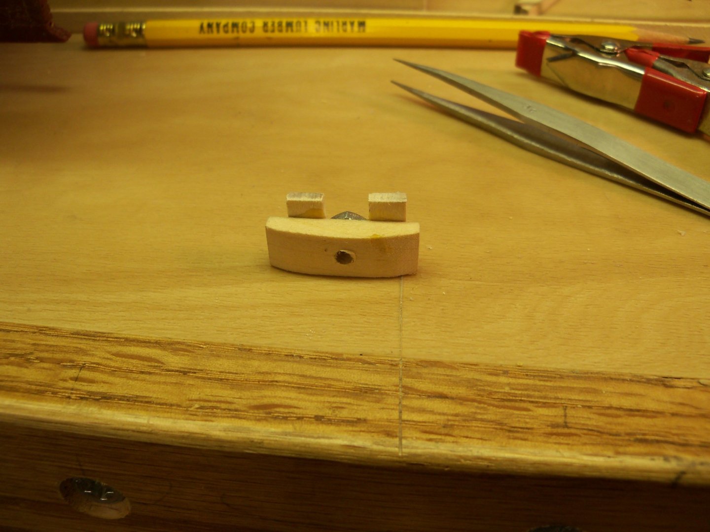
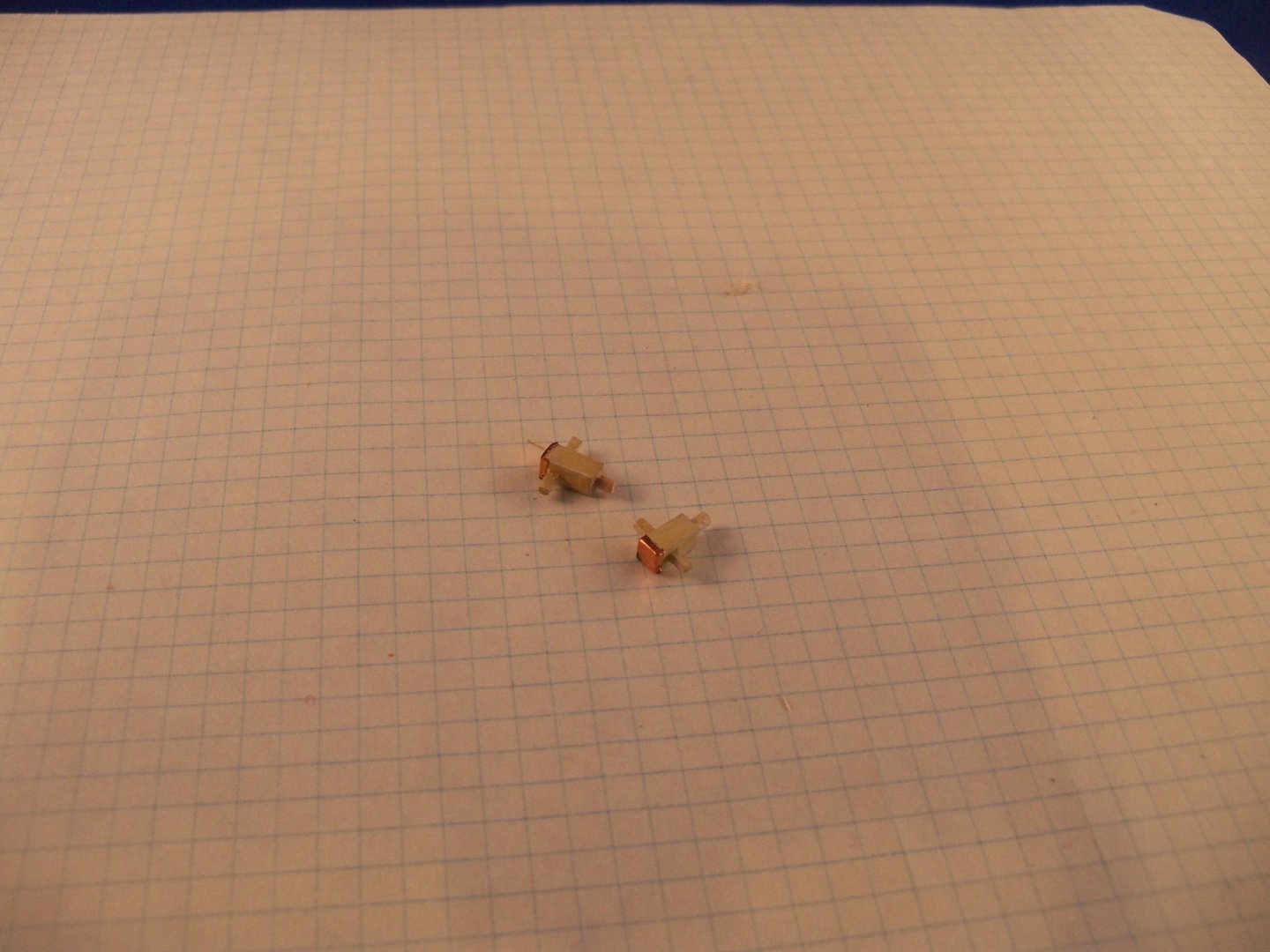
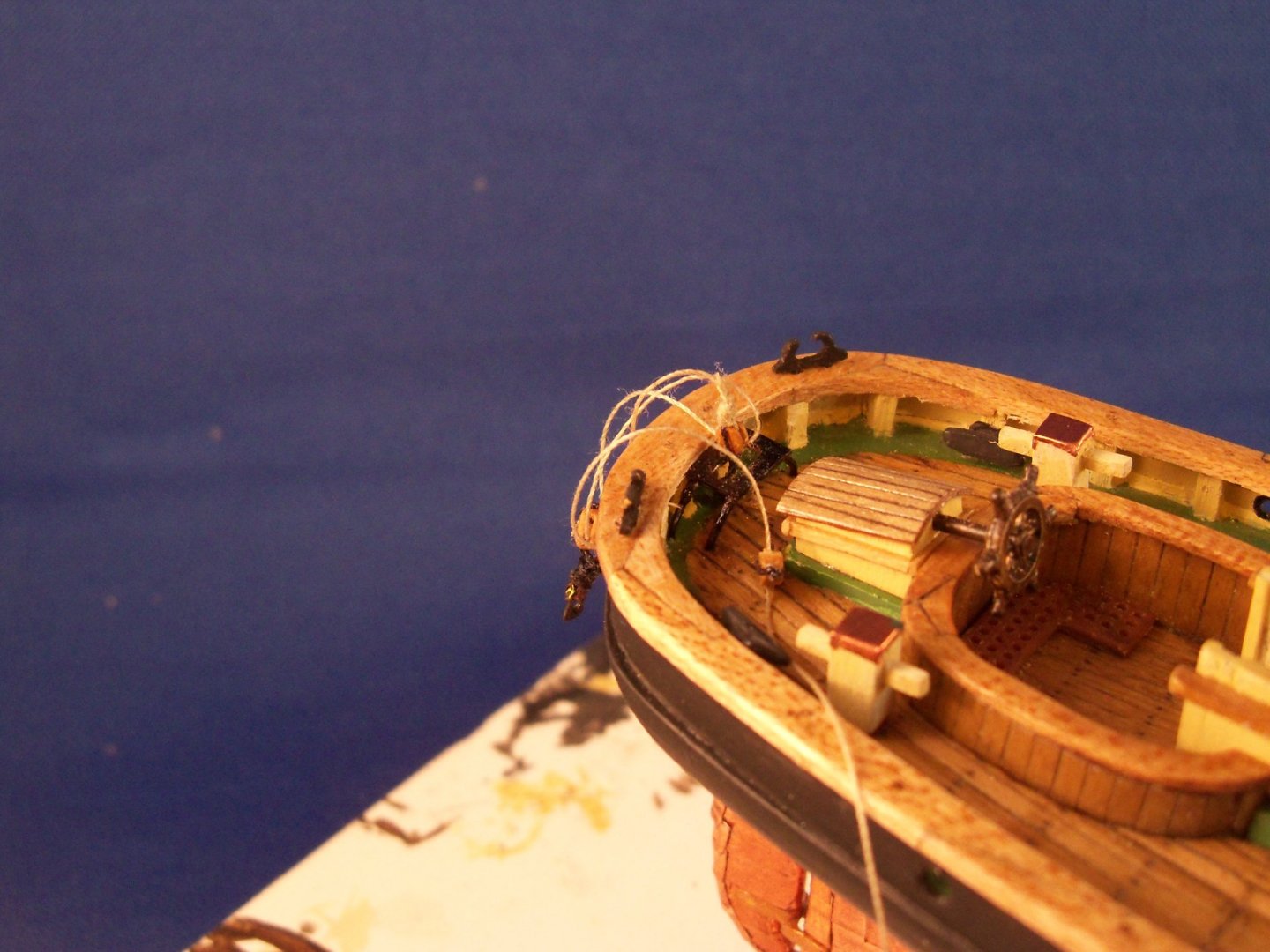
I continued working on a few more features of the bowsprit by forming three turnbuckles which the plan refers to as stretching screws. I previously put a small tutorial in the Shop Notes section under “Metal Work, Soldering & Metal Fittings”, so I won’t repeat it here. The topic listing is Turnbuckles and it was entered on March 16, 2018. Once these were made, I worked on the stay fittings that are mounted on the stem. The details for these fittings on the plans were rather vague. They appear as a pair of separate pieces with a gap in between them. With the thickness of the stem being about 12” on the actual ship, I thought this to be rather unlikely since the pin of the shackle would need to be over 14” long to tie it together. I thought it more likely that the fitting ends would be bent around the stem and joined together similar to the gammoning iron above. This would allow the use of a much shorter pin on the shackle and a more secure connection. (Or so I chose to believe, and thus was the way I made mine.) Anyway, the upper one is a single eyed fitting with a shackle to join to a seized eye spliced end for the forestay. At this scale, shackles were still beyond my skill level, so I substituted simple brass split rings for them. The lower one is a double eyed fitting with two shackles. The top eye is to join a seized eye spliced end for the jibstay, while the lower eye is to join to a seized eye spliced end for the bobstay. The upper iron fitting was tackled first as it seemed simpler to make. A narrow strip of shim brass was heated and cut overlong. The strip was doubled over a metal bar the same thickness as the stem and the bend was pinched together forming a tab about 3/16” long that was then drilled for the brass split ring/shackle. Once the hole was drilled, the tab was filed to shape and the “shackle” was installed, bent closed and soldered. Since an actual shackle is a slightly elongated shape, I squeezed the ring slightly to imitate the shape. The lower iron fitting required quite a bit more filing to make the final shape, but other than that it was similar. The next feature I worked on was the splash rail at the bow. 1/32” maple was used to make the side pieces by rubber cementing the two pieces together and shaping them on my belt sander so that they would match. Once they were shaped and separated, half lap joints were cut into the tall ends at the bow before they were steam bent to match the curve of the cap rail. A separate piece of maple was carved for the intersection at the bow with half lap joints made to receive the half lap joints previously made in the side pieces. All of the pieces were then painted hull black on just the exposed surfaces and set aside to dry. Two coats of Minwax light oak finish were applied to the cap rail, sanding it down with #400 wet/dry sandpaper. While that was drying, the half lap joints of the splash rail were joined with carpenters glue off the model. (They were taped down to the original one piece cap rail to keep them aligned.) Once the glue set overnight, the splash rail assembly was set and glued onto the cap rail with carpenters glue after scraping the finish off several spots of the cap rail for the glue. When the splash rail was finally fixed in place, a small round file was used to make the notches on the topside for the rigging lines and touched up with hull black paint. Here is the finished splash rail in place below. Since the face of the splash rail on the model was barely 1/16” high, I decided to skip trying to put the ships name on it. (The printing would have to be smaller than the fine print on contract papers.) Next on my list was to make some of the metal deck fittings. Some of them, like the pumps, ventilator, stove pipe and cleats, were simply cleaned up, painted and glued with CA into predrilled holes in the deck. The eyebolts were blackened before installation with medium CA. Some of the other metal fittings had to be custom made. The crossed pipe guards were bent from four pieces of .022mm stiff blackened wire around a U shaped metal form. Pairs of these U shaped guards were crossed over each other and were glued into four predrilled holes with medium CA glue. The crossed joints at the tops were soldered together once in place on the deck. The photo below shows the guards in place. The boom buffer fitting was also custom made and due to the very limited space available to install it and the related eyebolts and blocks, it was a rather tough one to make. The photo below shows that it was basically a bent four legged “table” with an oval shaped hole in the top. The photo also illustrates the value of not permanently attaching the deck structures until most of the rigging is in place, especially when building at such small scales. Imagine trying to do a feature like this with the wheelhouse in the way! I bent two overlong pieces of the .022mm stiff blackened wire over a wide U shaped form to make the supporting legs. The “table” top was a flat rectangular piece of brass with three overlapping holes drilled in a row in the center and then filed smooth into an oval shape. The “table” top was placed bottom side up with the legs clamped in place to the bottom and soldered together. Once the “table” was completed, it was set into position and using the tips of the legs to mark their positions on the deck, four holes were drilled. The height of the top was adjusted by shortening the legs. It was cleaned up and blackened. Now a hole was drilled for a blackened eyebolt to go directly under the “table”. A single 3/32” block was tied to the eyebolt with a long link passed through the hole in the “table”. The “table” legs and the eyebolt with the long link were glued with medium CA into their predrilled holes at the same time. (Could have used another set of hands for that, but there was no room.) Another blackened eyebolt was glued to the deck about 1/8” from the “table” toward the starboard crossed bollard with another single 3/32” block tied to it. A 1/8” double block was stropped with a pair of opposing 4mm hooks for later attachment to the main boom sheet band. Using the .20mm tan rigging line attached to a becket on the first single block. The line was first run through the double block, back through the single block, back once again through the double block and finally through the second single block for later tying off at the crossed bollard. I thought that hooking up this block and tackle arrangement would be easier to do at this point, rather than waiting for more obstacles to work around later. At this time I questioned the fact that the plans called for two crossed bollards and an additional four uncrossed bollards, especially since there were only four mooring ports. In the end after a search on pilot boats, there seemed to be a lot of conflicting opinions on that subject. Some said anywhere from two to six, and some just called for cleats rather than bollards. In the end I chose four, one for each mooring port. The ones at the bow were just straight posts, while the ones at the stern were made with cross bars. The cross bar bollards are shown below. Taking a length of 3/16” square basswood, I cut four 3/8” pieces and filed down the lower portion into round mounting pins. The cross bars being rectangular in cross section needed matching holes in the posts. I made the bars from 1/32” x 1/16” maple, so I drilled two 1/32” overlapping holes and filed the opening to match. I found that exposed ends of timbers in this era were capped with copper for protection from rot, so after painting them light buff deckhouse I put some of the copper tape from the hull on the ends. Here is a photo of them on the model. As I look at them now I feel that the timbers look overly large, so they may be reduced before gluing them in. I looked over a rather poorly cast anchor and decided to modify it to make it a bit more realistic. The shank and the shackle were OK, but the cross bar stock was basically a lump on the side of the shank so it was filed off and custom made with a length of .022mm brass wire. I drilled a .028mm hole for it in the head of the shank to leave a little extra room allowing the stock to fold up if that’s how I want it displayed, because at this point I have yet to decide. The wire for the movable stock was heated, cut to length and a right angle bend was made on one end. This movable stock required two ball shaped end caps and a stopper ring near the middle. These were all made from the Britannia coaming walls that came with the kit. The first step was to cut a slightly oversized flat round disc from the wall and thin it down to the desired thickness of the retaining ring. Then a .022mm hole was drilled through the disc. The straight end of the stock was slipped through the hole in the shank and the ring was then soldered to the middle of the bar and then filed down to its final diameter. Since the ring was so close to the shank, I used a couple of heat sinks to make sure that the heat wouldn’t deform the shank. There was also a small chain and pin used to lock the stock in place, but at this scale it would be very difficult to make so I just skipped that detail. The two end caps were made similarly, but once cut; I left them twice as thick as the stopper ring. They were both drilled, but only about halfway through. After they were both soldered on, their caps were filed into ball shapes. The anchor was then painted iron /hull black. The photo below shows the finished anchor sitting on the deck.


-
While I am hardly an expert at soldering, I think some kind of heat sink may have prevented all of the heat being transferred to the anchor. The melting point of the anchor was probably lower than that of the solder so isolating the heat from your anchor may have prevented the mishap.
-
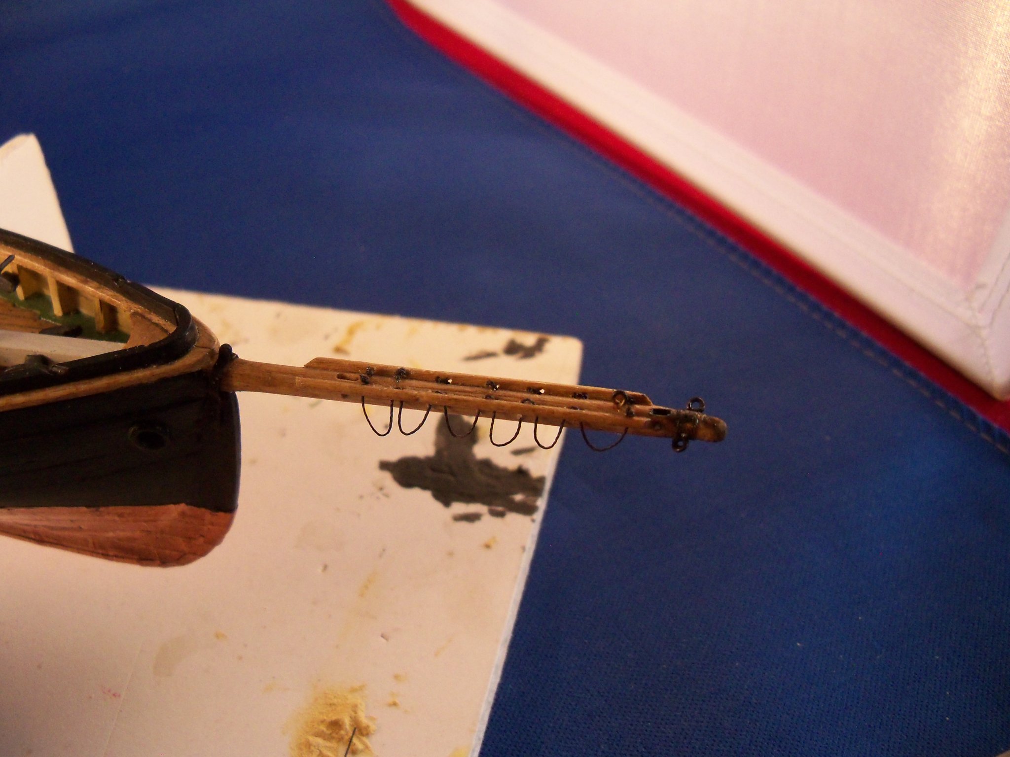
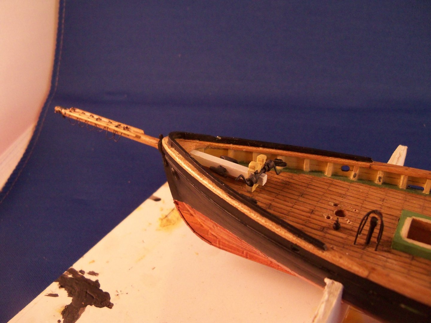
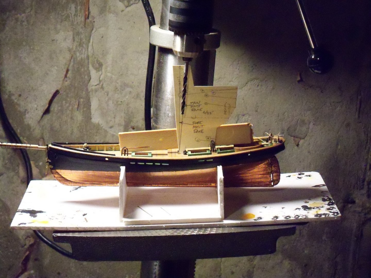
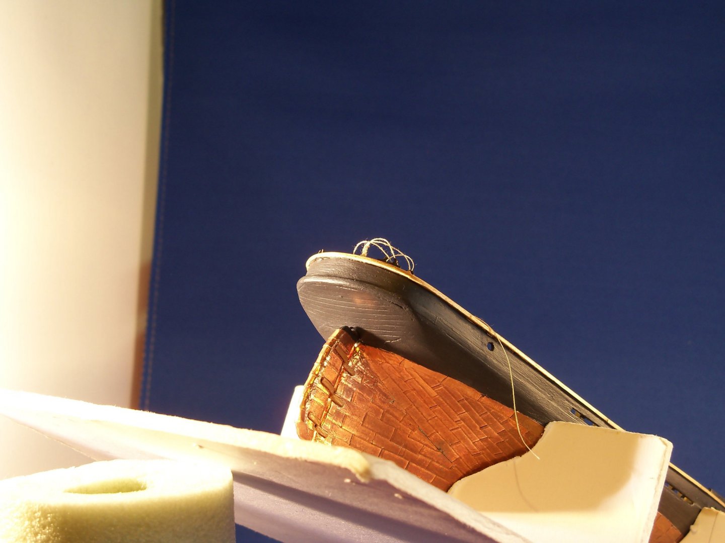
At this point all of the holes in the bulwarks were formed. A notch had been cut for the bowsprit before doing the cap rail using a 1/8” square piece of basswood for a guide and the scuppers were also formed while planking the bulwark. But I still needed to drill out the oval shaped holes for the mooring lines. These four holes were located and drilled by hand with an undersized drill bit held in a pin vice. Then they were shaped with a fine round file and some #400 wet/dry sandpaper glued around a small dowel. The holes for the hawse pipes were drilled similarly and the pipe lips were glued in place with CA. Looking again at the mooring holes, I questioned the fact that no similar lips had been provided in the kit for those mooring holes. The plans appear to show them, but since mooring was more likely not done with chains there wouldn’t have been a lot of wear on the holes. For now, unless I find out later that they actually had metal lips, I’m not going to add them at this time. This is a shot of the mooring holes as shown on the plans below. The ship was then set back in the cradle with the waterline level to the base. I made some templates from the plans out of some stiff card stock showing the rake angle of the masts to the deck. The cradle was securely taped down to the base plate of my drill press and the plate was tilted to match the angle on the template. Here is a loosely staged photo of the set up for drilling the main mast below. Then being a little leery of making a hard to correct later mistake, I triple checked the setup before actually drilling the holes. Once the hull was drilled for the 5/32" masts, I went to the plans and located all of the other holes needed in the hull. These were then drilled for all of the items that would be difficult to get at once the rigging was begun. That included all of the cleats and eyebolts in the stanchions that needed to be blackened before installation. The bowsprit was tackled next. I took some of the 1/8” square basswood supplied with the kit. The portion exposed beyond the stem was filed round and cut to length as shown on the plans. Several holes were then drilled for the two cleats inboard and the two sheaves for the stays outboard. The sheave holes were elongated and a brass pin was drilled through the sides to act as the sheave. There was now a bit of ironwork to be tackled. (Metalworking’s something that I am not very skilled at yet.) The gammoning iron and the majority of the rest of the ironwork was suggested in the instructions to be formed from card or tape because of the small scale, but I had done that in the past and wanted to try doing ironwork with actual metal on this ship wherever possible. Since the pintles and gudgeons had worked out ok, I thought it was time to continue pushing the envelope of my metal modeling skills. Taking a sheet of thin brass shim stock, I heated it with my torch and cut some very narrow strips with my coping saw. I cleaned up the edges with a fine flat file and went to my scrap maple bin and made a form to bend the strips into the required shape. Next time I try this method, I will make the form out of metal as the maple (although it’s a hard wood) became deformed and was only good for one use. When I had the two pieces formed, the top end was soldered together. It was painted hull black and loosely slipped into place until the bowsprit could be installed. The wood jackstay was made next from 1/32” square maple. These were then glued into place with wood glue. Once they were set I drilled the dozen closely spaced holes along the joint of each jackstay as shown on the plans for the gasket ropes. I stained the portion of the bowsprit beyond the bulwark with Minwax light oak and inbound with white paint and once dry, the rope gaskets were threaded in place. The next item to make was the metal wry band at the end of the bowsprit which required an eyebolt on each side and the bottom. The band itself was simply a short section of hollow brass tubing that was a snug fit near the end of the bowsprit. The hardest part was drilling the holes for the eyebolts on the round surface. I did find that by cutting the tails of the eye bolts off just long enough to go through the band, I didn’t have to worry about drilling through the bowsprit itself so the holes were drilled while the band was slipped onto a scrap piece of dowel. The eye bolts were soldered to the band and a thin fine round file was used to smooth out the inside of the band. This was then painted with hull black paint before installation. As the band was about to be slipped into place and glued, I discovered that I had forgotten the old carpenters’ adage “measure twice, cut once”. I realized that once the wry band was installed there wouldn’t be any bowsprit beyond it! The bowsprit was about 3/32” short. While that may not sound like allot, @ 1/8” scale that’s about 9” off. Rather than remake the whole bowsprit, I actually shortened it some more. Cutting it back to the middle of the band, I added a short piece to the end of the bowsprit reformed to the correct overall length and applied CA to the joint as it would be hidden inside the band. Fortunately I don’t think that the lines will put too much strain on the joint so I may have just lucked out this time with a quick fix to hide my error! Before the bowsprit could be mounted on the ship the bitts with the windlass fitting needed to be cleaned up and installed. I formed a pair of bent brass wires for the portable handles, drilled holes in the windlass barrels, and glued them with AC. The upper portion of the bitt post corners were eased with a file and I carefully painted the windlass black and the bitts light buff deckhouse. Once dry the bitts were glued into the deck with medium CA. Now the bowsprit was slipped through the bulwark and into the hole in the bitts. The cleats were glued to the inboard end of the bowsprit. And finally, the gammoning iron was glued to the stem to finish the bowsprit installation. Here is a photo below of the completed assembly as it stands now. As you can see from the photo, I installed an eye bolt according to the plan detail apparently for attaching a block for the jib downhaul. I say apparently as there isn't one shown for the fore stay sail block. Also, the uphaul end of the same line just shows the block being secured to the stay itself. Before I start the rigging I shall have to investigate further to see which attachment method was actually used.


-
uploading pictures
BETAQDAVE replied to David56's topic in Using the MSW forum - **NO MODELING CONTENT IN THIS SUB-FORUM**
Reposted under seperate topic. -
You work at 1:175 and seem to have much less trouble putting in details than I have @ 1:96!
-
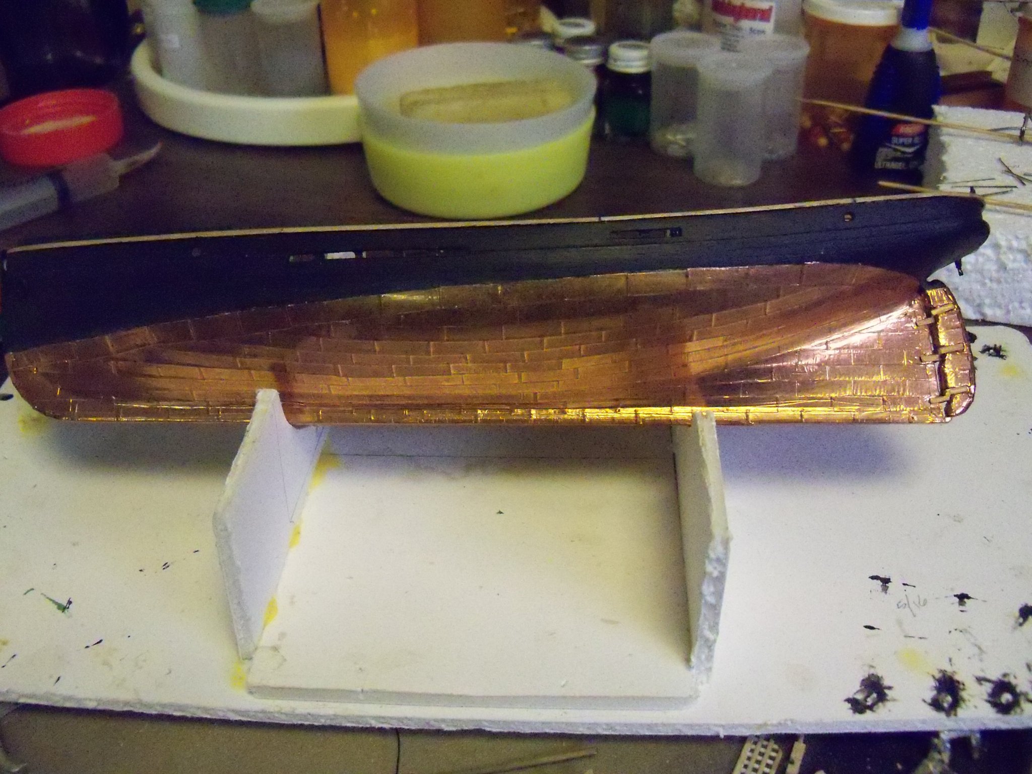
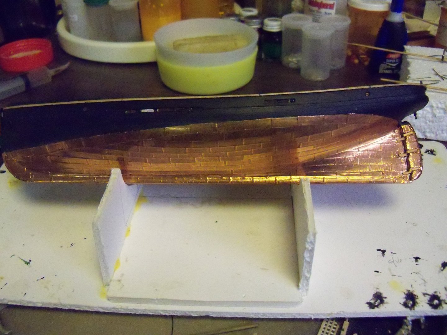
Now it was time to tackle something that I had never done before, coppering the hull! I spent a lot of time combing through all of my books, magazines, MSW and finally the internet for needed details. All in all, I came up with my own method. Sorry, but I didn’t take any pictures of this process. Rather than trying to split the copper tape that came with the kit which would leave me with a scaled 12” width which would leave me with no overlap, I just bought some copper tape used for stained glass work from Hobby Lobby instead that was 5/32” wide. That’s very close to 14” at scale which was the actual width of the copper plates on the ship. I decided against trying to indicate the nails on the plates for two reasons. For one thing, they would be very tiny at this small scale. And two, since they were hammered in flat they would leave very little visible evidence that they were even there. So cutting them to the proper length of 50” at scale was all that was required. I started by mass producing the individual plates by simply stretching out the tape and stepping off tic marks on the edge of the plates with my old drafting dividers with the opening set at that scale 50” length. Once the tape was marked, I simply cut them with a pair of scissors, being careful to make the cuts perpendicular to the edge. The only tedious part of making individual plates was separating the cut plates from the backing paper. It required a steady hand with a sharp scalpel and a lighted optivisor on your head to see what you’re doing. Just drawing the layout for the coppering on the hull was the next problem to solve. Since the exposed width of the plates was 12” at scale, I locked a pair of my old drafting dividers at 1/8” and I inserted the shouldered points into both legs to keep from poking the points too far into the wood. The lines of the strakes were then laid out by placing the bottom leg on the previous line with the other leg held perpendicular to that line and poking a hole into the hull with the upper leg, spaced about every ¼” along that line. When done, I just connected the poke marks with a flexible straight edge and a pencil forming the new line parallel to the previous line. This allowed me to leave a scale 12” exposure and still have a slight overlap. As near as I could determine from the plans, the gore line between the upper and lower belts was a line that more or less ran parallel with the keel from around the midpoint of the hull and then curved up to within to about a strake or so below the waterline at the sternpost. So basically, this lower belt just covered the skeg of the hull. The next strake of plates continued up the hull until it overlapped the gore line. I ran the plates just beyond this line and trimmed them off so there was a slight overlap with the upper belt. The first strake was started along the bottom edge of the keel which allowed the first plate to reach the knuckle of the hull and run up onto the hull itself a bit. Then the next strake would start at that knuckle, thereby overlapping that first strake. From there on, I just kept on marking one strake at a time parallel to the keel until I reached the gore line of the upper belt. From there on the strakes were marked parallel to the gore line of the belt. I continued this procedure, alternating port and starboard sides of the hull to ensure the layouts would align with each other at bow and stern. Once I had all of the strakes drawn on the hull, the area to be coppered was given two coats of polyethylene and sanded smooth to ensure a good bond with the tapes adhesive. At this point I noticed that I seemed to have forgotten to make the rudder, so I glued up three pieces of 1/8” basswood and filed it to the proper shape. Rounding the rudder post portion, I left it extended about 3/8” to fit into its hole in the hull. Notches were filed for the hinge joint. The very upper portion that was above the waterline was painted hull black and the coppered portion was given two coats of poly. I decided to make the pintles and gudgeons from brass rather than the paper suggested in the kit, so I needed to bone up a bit on making ironwork and soldering. Narrow strips were cut from some shim brass sheets and bent around some 1/8” forms into U shapes. The U shapes were stacked on top of each other, the ends cut to their proper lengths and were soldered together in pairs while still on the forms. At first I was going to blacken them, but decided instead to paint them a bronze color, since I remembered reading somewhere that bronze and copper were more compatible than iron and was used more for ships of this era. I started coppering the ship at the sternpost with a full plate, overlapping that odd horn on the bottom of the keel. The plate was just trimmed around the horn and pressed into place. The next plate in line was overlapped, leaving the previous plate with a scale 48” exposure. This was repeated up to the front edge of the stem and trimmed to match its curve. The hull was then reversed and this strake was repeated on the other side. About every third plate or so, I used a wooden stick to firmly burnish the plates. The second row of plates was laid similar to the first row but starting with a half plate at the sternpost. When the rows of plates for the lower belt came to the gore line with the upper belt, the plates were left overlong and then trimmed off with a knife leaving a slight overlap. Once the bottom belts for both sides of the hull were finished, I went on to work on the upper belts. The same procedure was followed there until the top rows of plates were trimmed off at a scale 8” below the waterline. A final strake of plates was then laid parallel to the waterline with the top edge of the plates 6 scale inches above the waterline. Going back now to the the very bottom of the keel, I needed wider plates to cover the bottom and be bent over the keel edges to overlap the bottom row of plates. Since the 5/32” tape was a little bit too wide, I used some of the ¼” tape that came with the kit. This allowed about a 1/16” of lap on the sides which looked about right. I continued coppering the bottom of the keel with 48” scaled lengths of exposure that were offset from the bottom row of plates by half, right up the curve of the stem to the waterline, but switched to plates that were cut to 5/32” lengths so the plates could more easily follow the curve. Returning once again to the rudder, it was given its coat of copper plates below the waterline. I used plates long enough to start at the rear edge on one side and finish at the rear edge on the other side. As it went around the front edge it was carefully trimmed at the pintle notches. Then the rear edge of the rudder was finished similar to the wrap at the stem of the ship. The hole was drilled for the rudder post in the transom, the pintle and gudgeon assemblies were then pressed in place on the edge of the rudder and glued with medium AC. The rudder post was then slipped into the hole in the hull and the gudgeons were pressed into place on the sternpost and also glued with medium AC. Once I had all of the copper plates in place, I burnished all of the plates with my wooden stick to ensure a good bond and brushed on a coating of poly to seal it. The hull was set upside down and left to dry for a few days. OK, at least this is a photo of the coppered hull when it was finished.
-
Mini Table Saw recommendations
BETAQDAVE replied to captainscott's topic in Modeling tools and Workshop Equipment
The one that I have was handed down to me from my Grandfather. None of the modern safety features but it's built like a tank! -
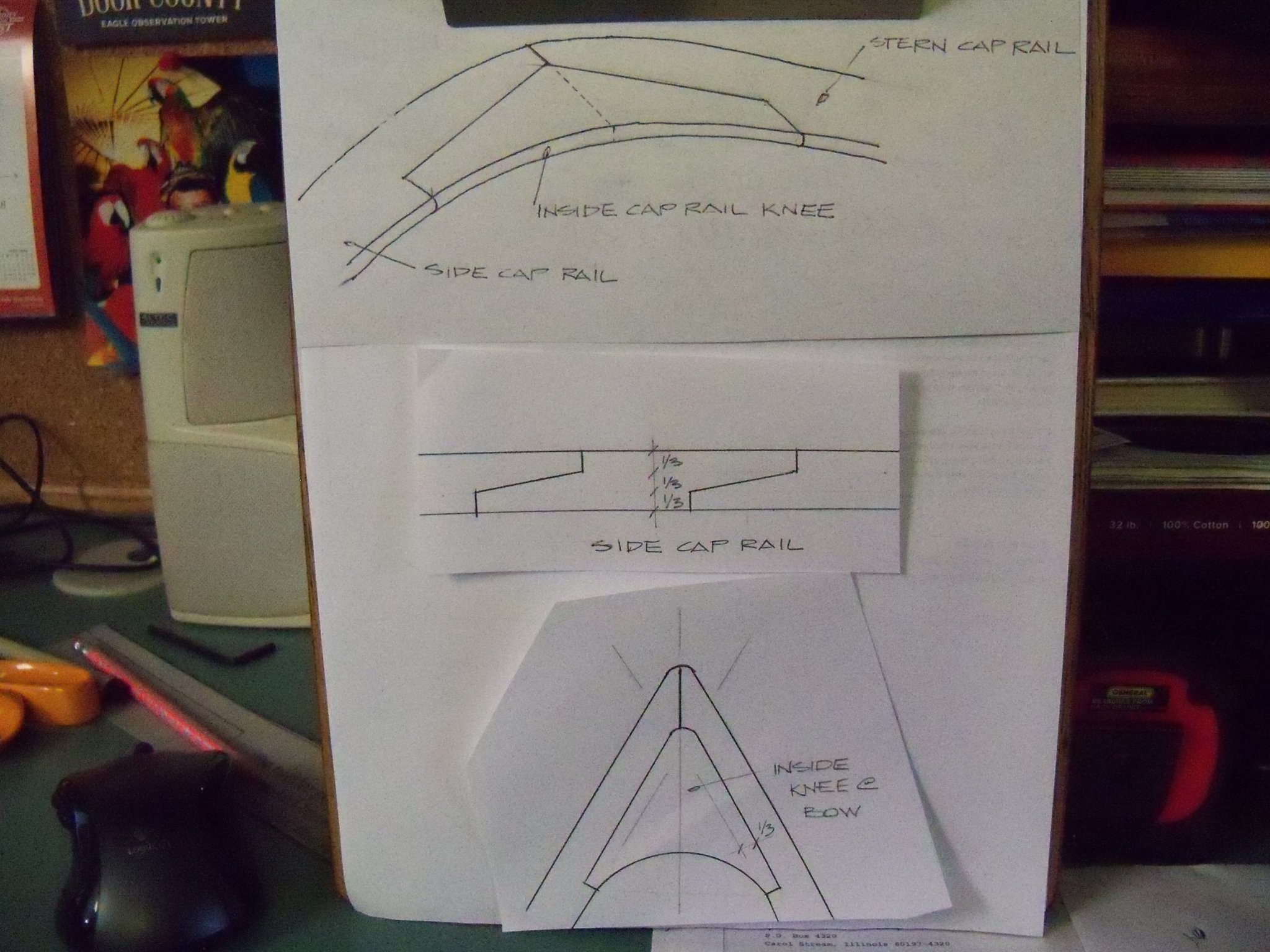
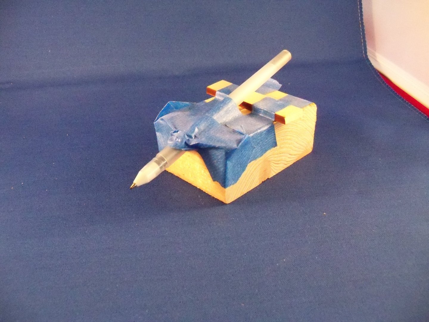
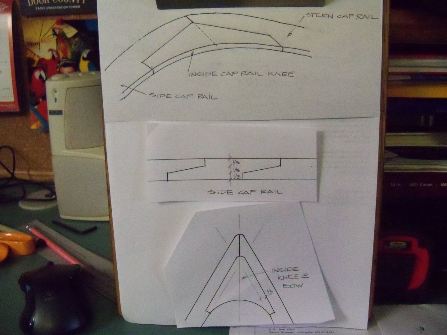
Switching gears now, it was time to work on the outside of the hull once again so the ship was now supported in the cradle with the waterline level with the benchtop. I made this makeshift waterline marker shown below from scraps and ran a line around the hull with the pen. Using an exacto knife I carefully followed that inked line with a depth guide clamped to the blade to limit the depth of cut to 1/32”. Then I cut a block of 1 ½” thick lumber to size and glued a piece of foam padding to the bottom side and drilled for two screws through the block and into the carved out companionway areas so I could mount the hull upside down in a vice as needed. Now I proceeded to shave 1/32” from the hull with a narrow chisel one plank width at a time using a plank as a guide. I starting from the waterline and worked my way up to and including the shear strakes. The shear strakes had been made early on from 1/32” x 5/32” basswood planks that followed the edge of the carved hull. At that time 1/16” wide by 3/32” deep notches were made in the shear planks and cut into the hull at the location of every third stanchion. Now a slightly overlong 1/16” square basswood stanchion was glued in place at every notch with carpenters glue and left to set up for two days to be sure that they were solidly anchored. The edges to be left exposed were painted light buff deckhouse. Then I steam bent a 1/32” thick basswood plank to follow the curve of the decks. This was then clamped to the notched stanchions to hold the false timberheads in between, which had also been painted light buff deckhouse, in their premarked locations. I glued down their ends with carpenters glue, and after this set up for a couple of days; the clamped guide board was removed. There were no details of how to plank the transom on the plans and I was unable to find any relevant details anywhere else for this type of ship. So, I planked the lower transom with parallel planks laid horizontally and ran the ends of the side planks to butt into it. I think that is referred to as a round tuck pattern. The sides of the hull were planked with both 1/32” and 1/16” thicknesses of 1/16” wide basswood in scaled lengths of about 20 feet. I started at the level of the lower deck with one row of 1/16” thickness. Two rows of 1/16” thickness were added above this row for the bulwarks. Two additional rows of this thickness were run below the deck shear. The upper bulwarks were made with two rows 1/32” thick planks. Where the scupper openings were located, I filed off the bottom 1/32” of the plank width before applying the planks. The remainder of the hull planks laid was all 1/32” thickness. The bottom row of 1/16” thick planks were blended into the 1/32” thickness below with sandpaper. The shear strakes and the decking were masked with Frog Tape and the inside of the bulwarks were painted with light buff deckhouse. Once the bulwarks were dry, the tops of all the timberheads were filed and sanded even with the top of the bulwark. Then the outside of the hull was finish sanded and given two coats of hull black to just below the waterline. As I mentioned earlier in this I think that I should have put a bit of a bevel on the edges of the planks so they would stand out better. Once it was painted black, it was hard to discern that they actually were individual planks and not a solid hull. It seemed like a bit of wasted effort there, but as I had never planked a hull before it was fun anyway. The cap rail was next. My first attempt was made in one piece as was suggested in many of the logs on MSW. I took a sheet of 1/16” basswood held down on the top of the bulwarks and used a pencil to run along the outside outline of the top of the bulwarks onto the sheet. The sheet was flipped over and remarked with the overhang added. The finish width of the cap rail was then added to get the inside edge. The inside edge of the rail was marked out and using my scroll saw I cut it just outside of the lines. I sanded the lines down to its finish size and laid it out on the ship. Although it turned out to be accurate, I was not happy with its appearance at all, since it looked like it was cut from a sheet, which does not make an accurate representation of the real thing. I didn’t like the look of the basswood for the cap rail either. However, since I had an accurate outline of the overall shape to work with now, I could redo it with some 1/16” thick maple strips that I ripped down on my full size garage table saw. I decided to cut it into four approximately 20 scale foot sections on each side and one additional section across the stern. Scarf joints were used at the joints of the sections together along the sides and a pie shaped filler piece was cut for the bow. At the stern a simple miter joint was made with a knee piece in between. Diagrams of the design for the joints made are shown below. Here is a photo of the joints as done on the model itself.

-
dull number drill bits
BETAQDAVE replied to BETAQDAVE's topic in Modeling tools and Workshop Equipment
His solution on the video has one drawback that is hard to overcome. The bits are so small you would need a microscope to see what you are doing to modify the cutting edge. However, for the larger size bits it would be useful. -
I've been having problems with numbered drill bits sized 67 to 80. While they seem to have no problems drilling wood, it appears that metal is another thing all together. Are they just dull or not made for drilling metal? Is it possible to be sharpened or just discarded? Some bits from the same brand new sets are good while others can hardly make a dent in soft brass even after prolonged drilling time. Perhaps it's just a question of getting what you pay for.
-
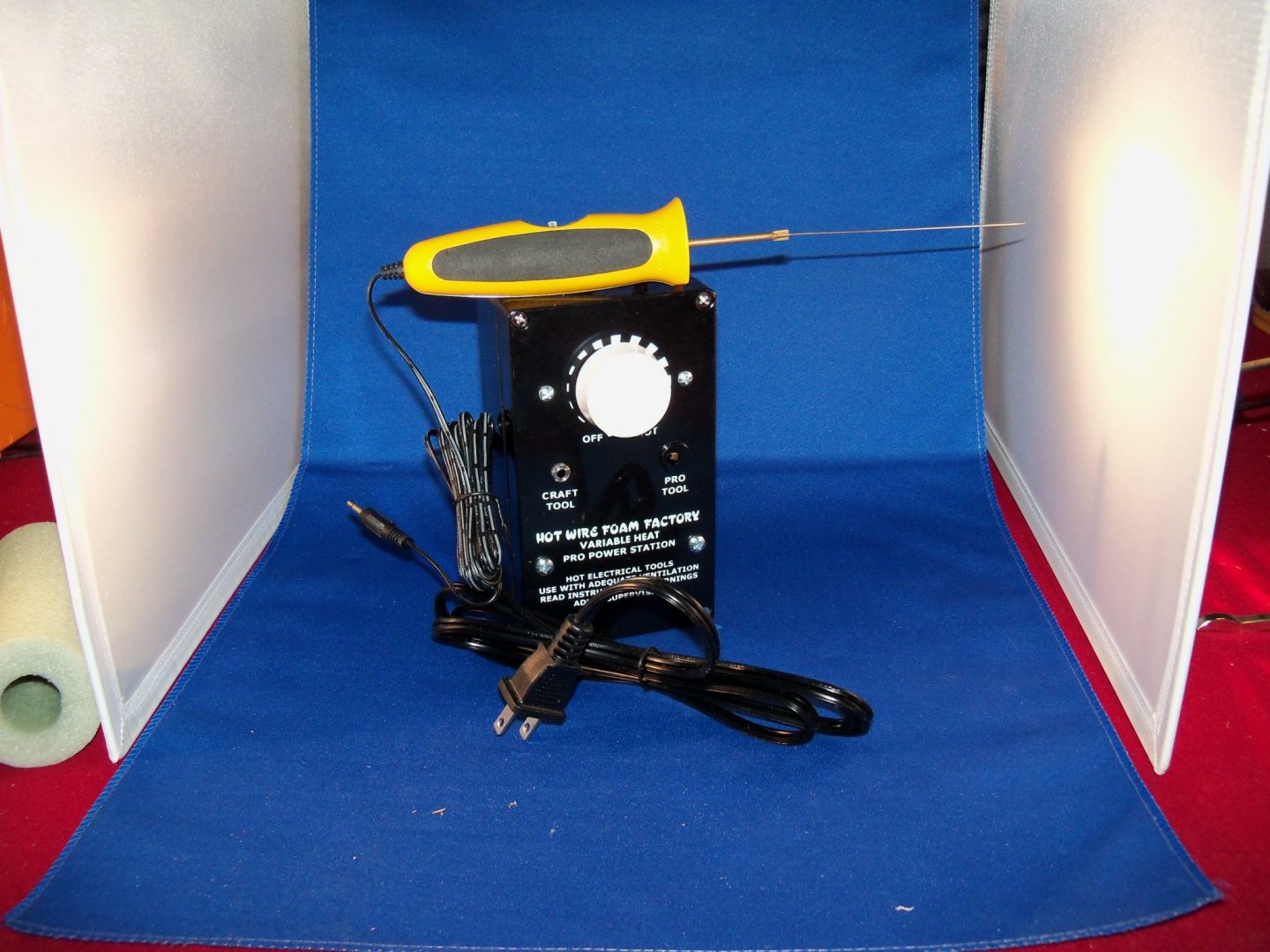
I don’t know how much foam cutting you do Bob, but if it’s a lot, using a hot wire system saves you all that static mess that sticks to everything. When I started making my wife’s X-mas lighted village display scenery those beads were everywhere when I used various saw blades. Saw blades can still be used for texturing, but to get a neat clean cut, a hot wire is the way to go especially when using the thick foam. Micro-Mark has quite a few of these cutters ranging in price from $25 to over $300. I finally went to this unit that consists of a variable heat power station and 4” straight wire cutter made by Hot Wire Foam Factory shown below that cost me $130. They also offer quite a few other accessory cutters.
-
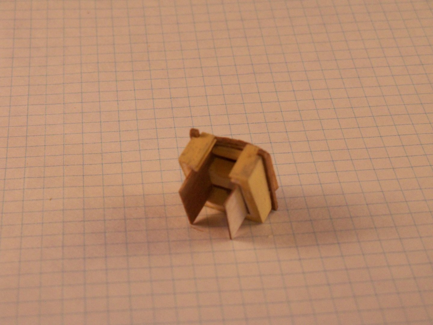
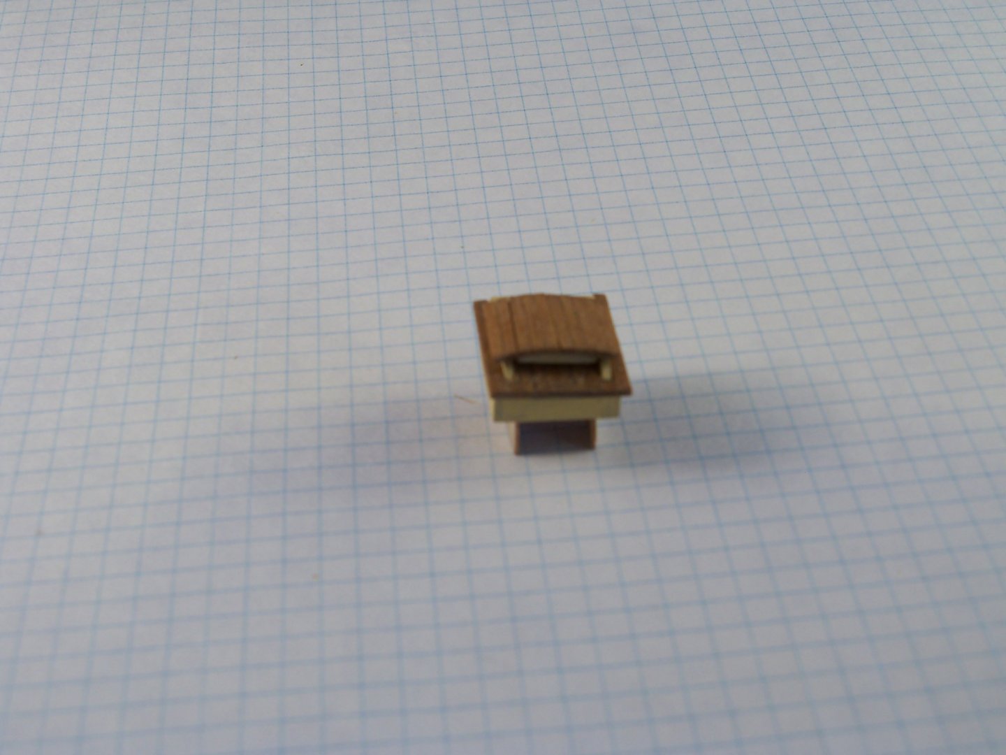
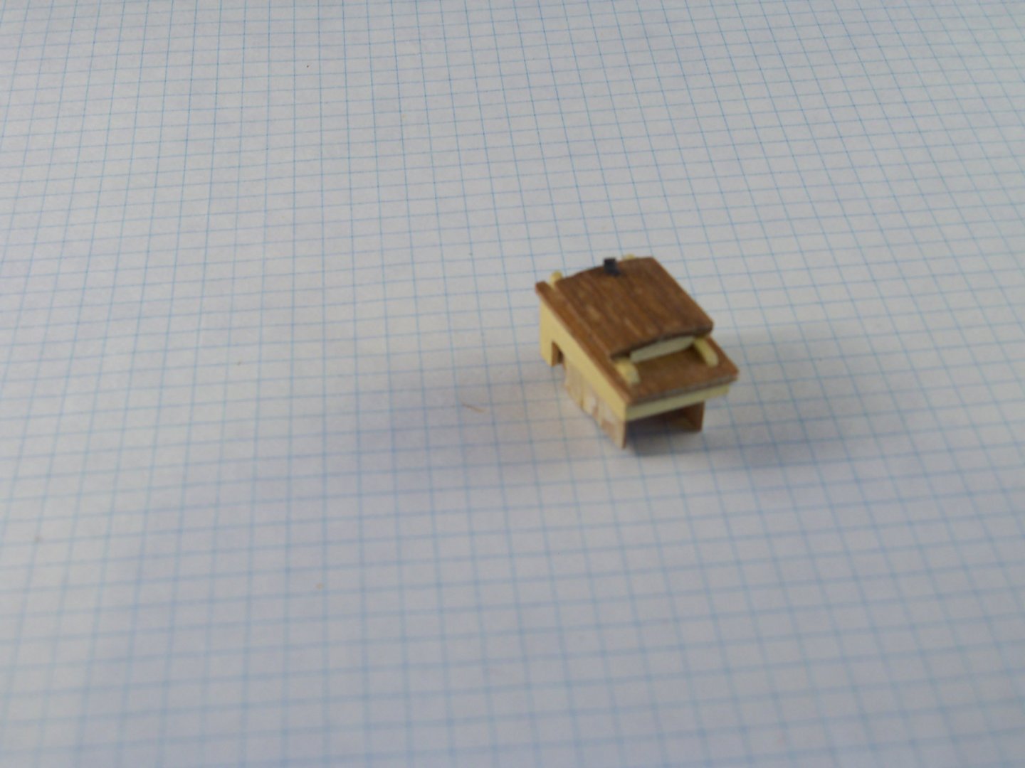
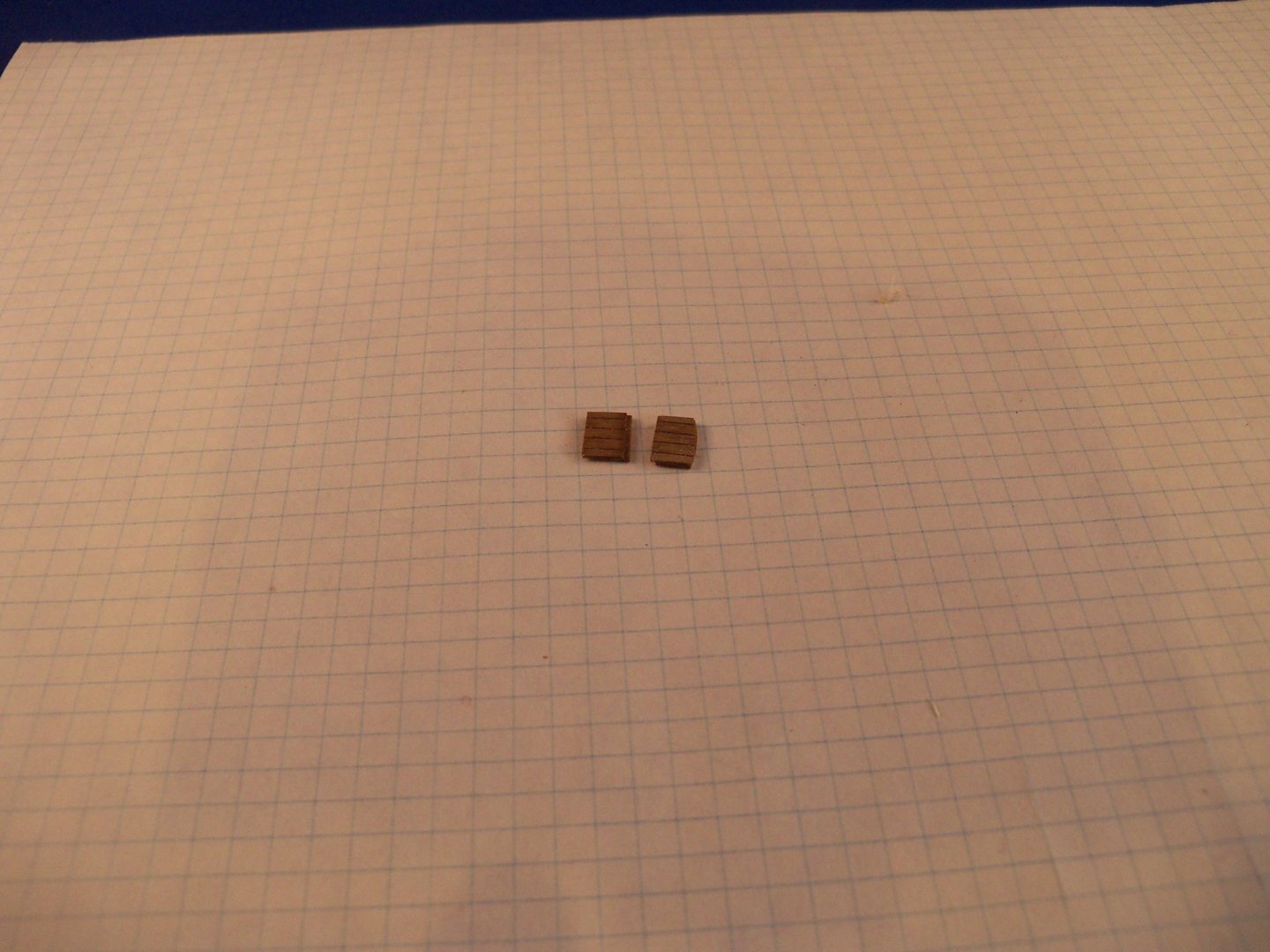
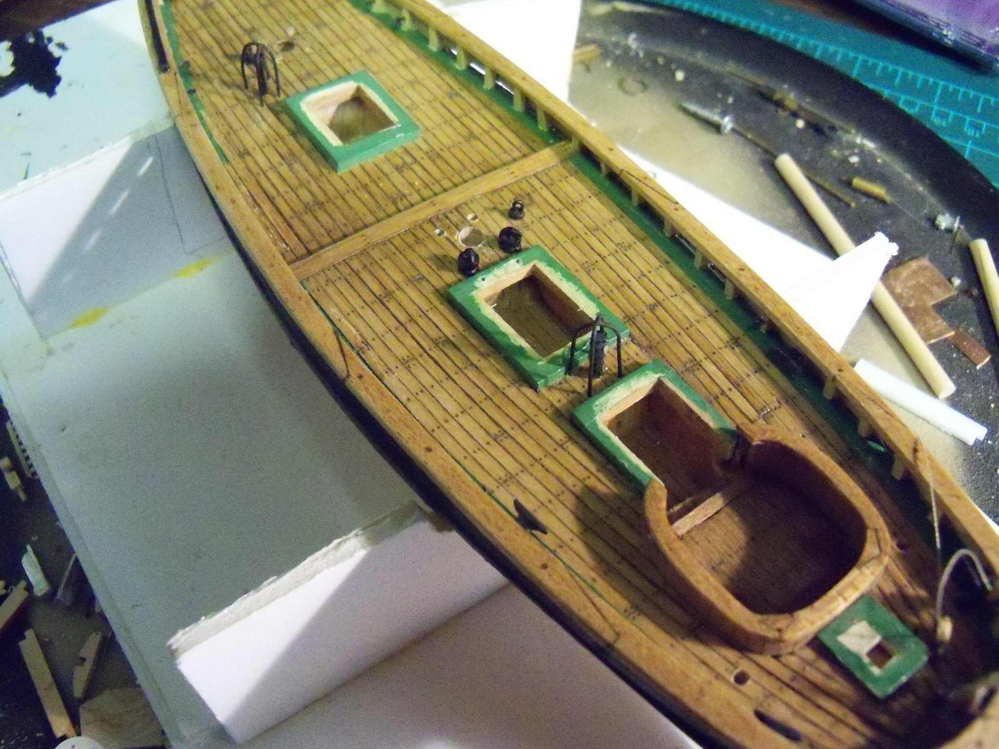
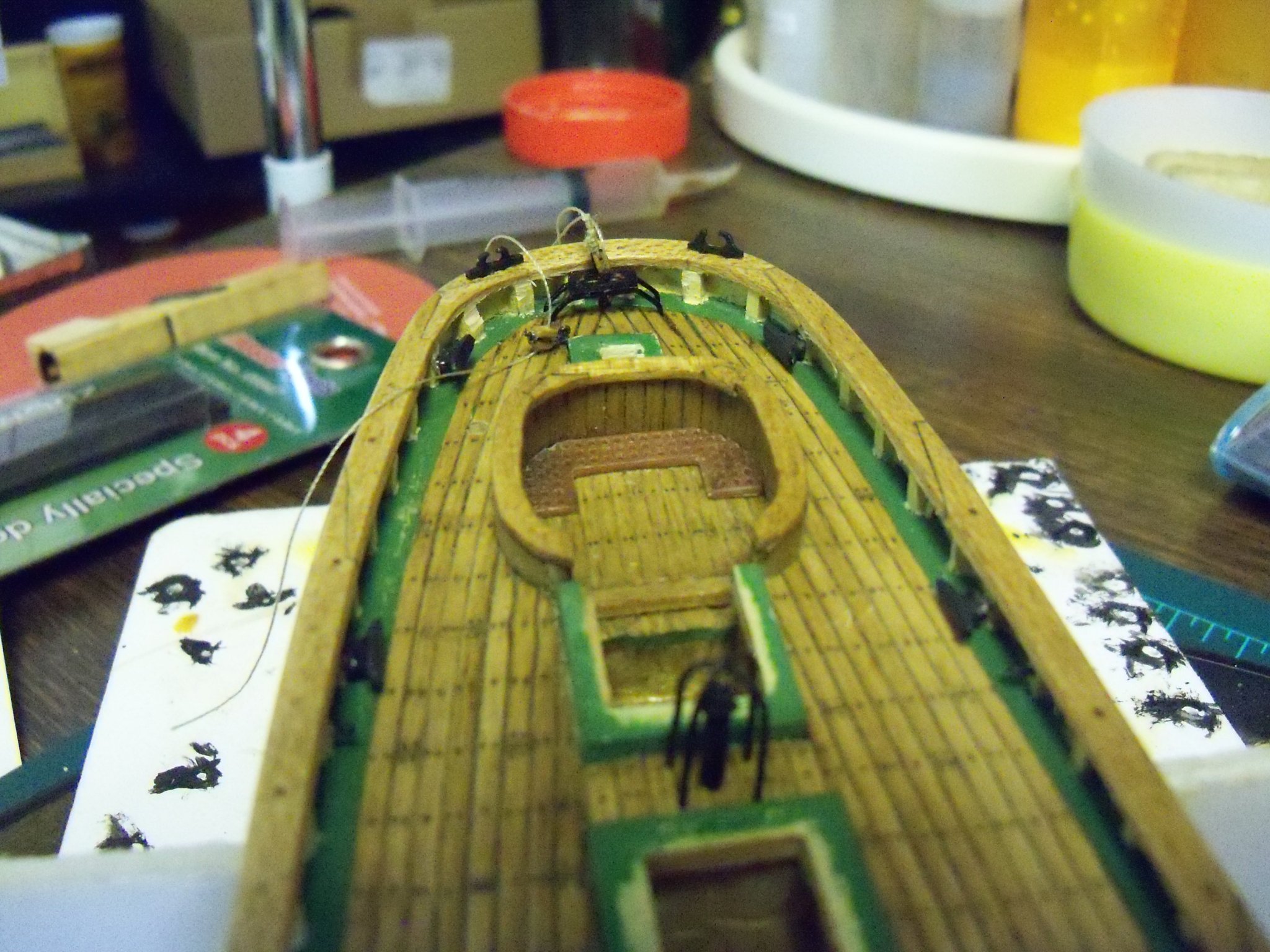
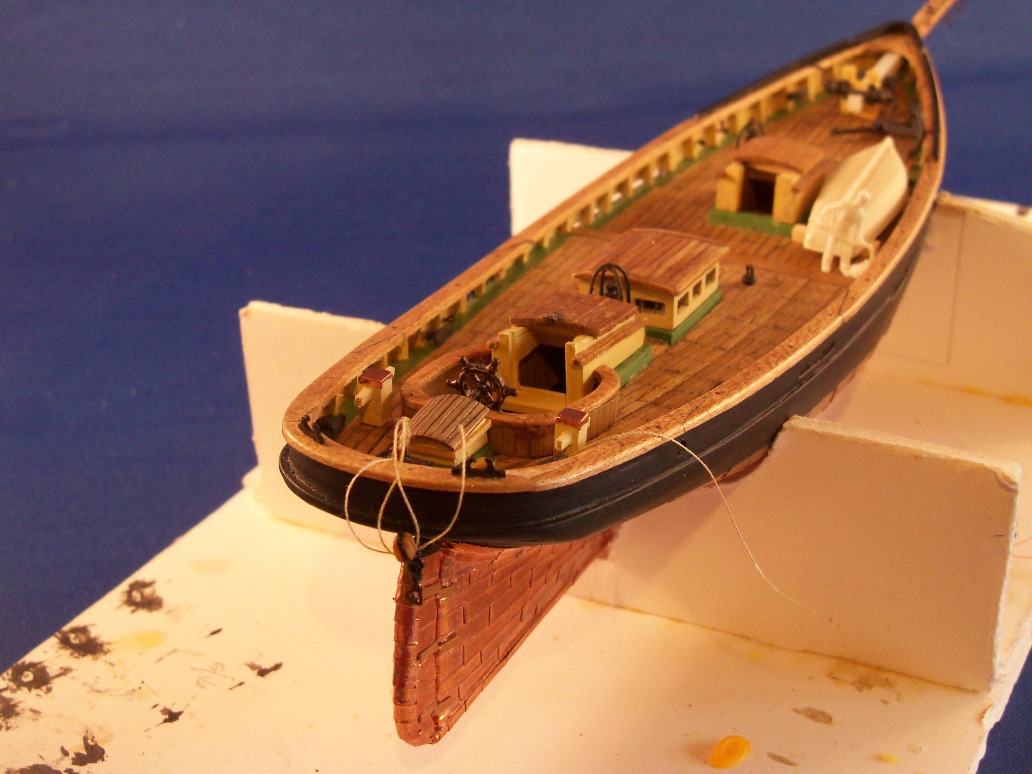
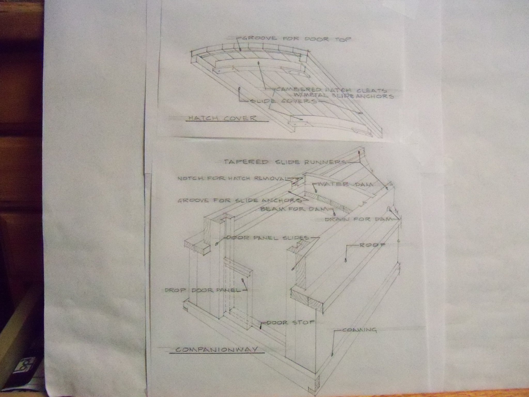
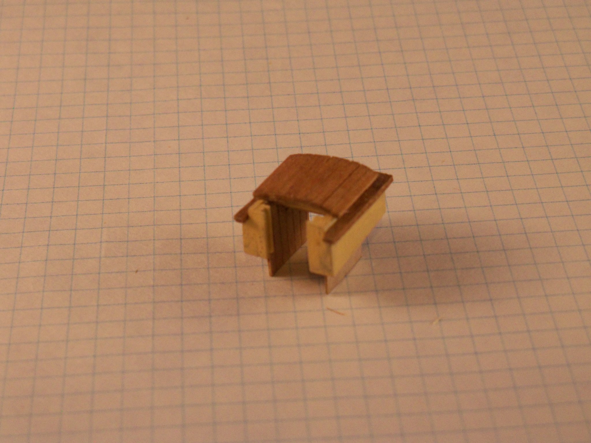
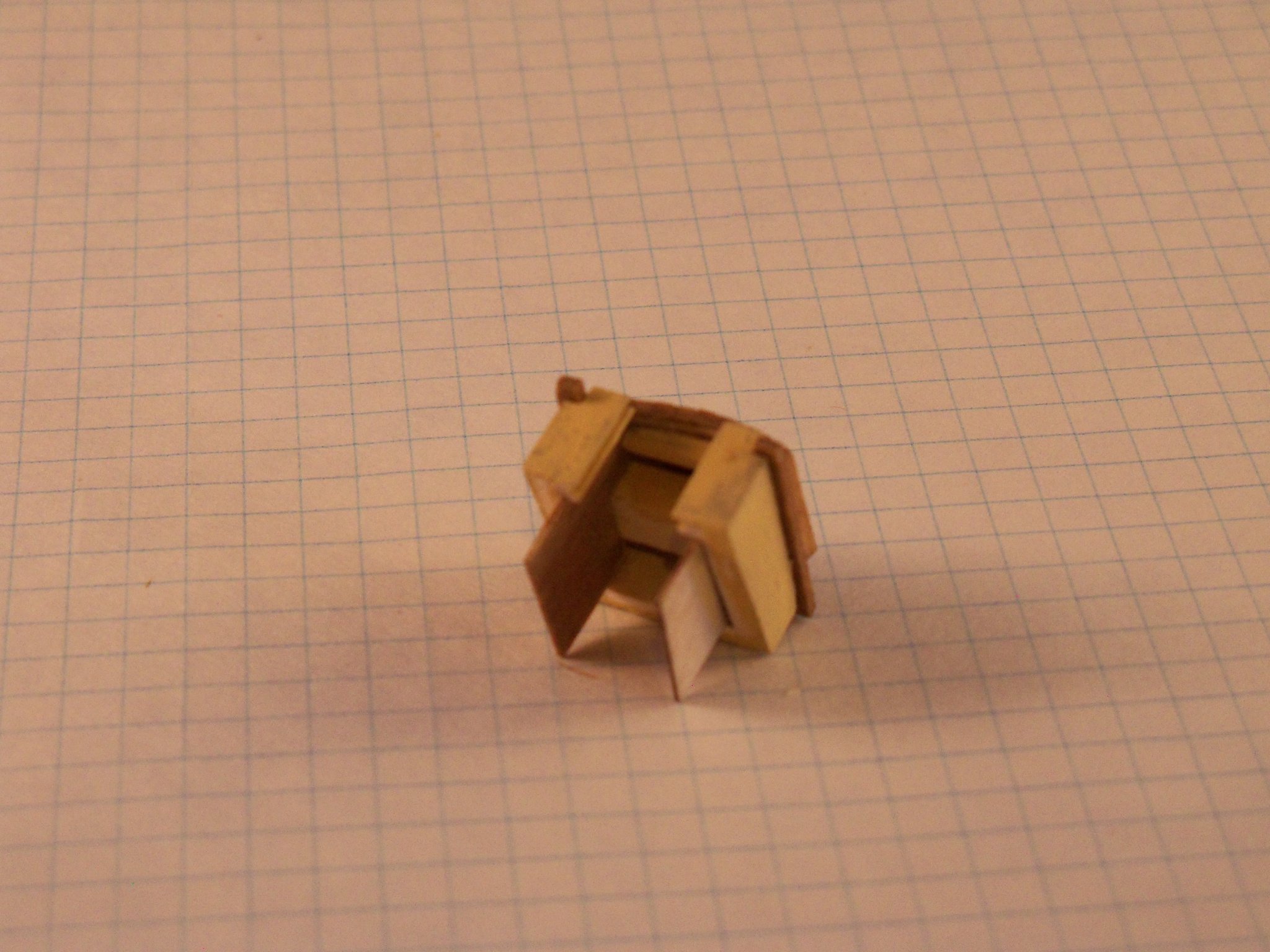
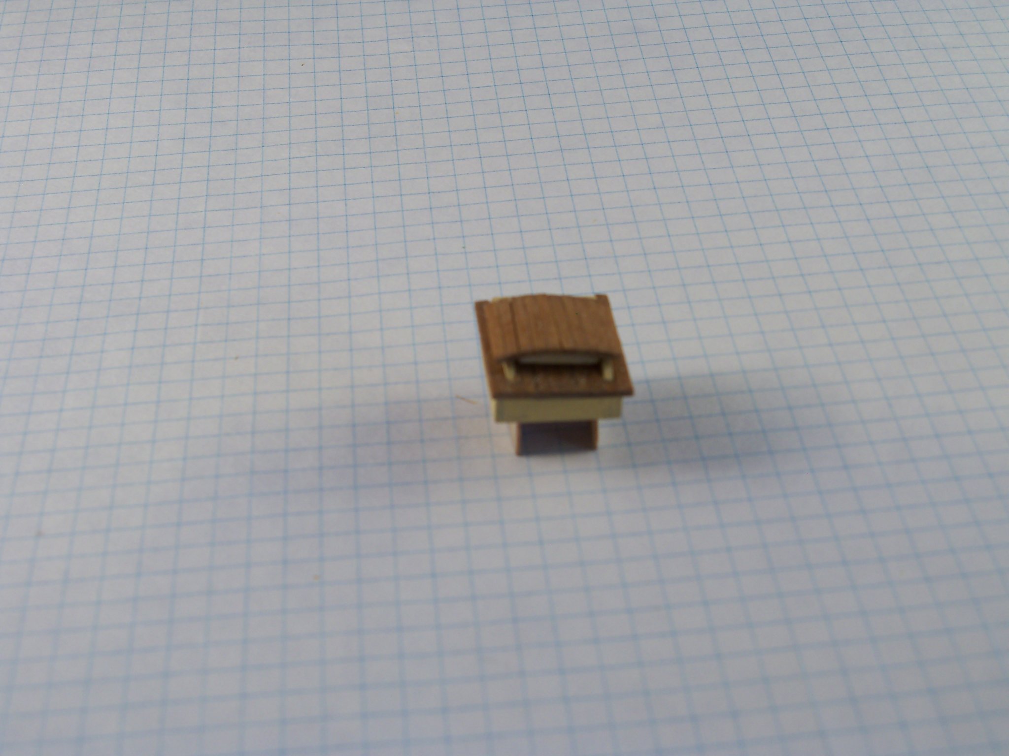
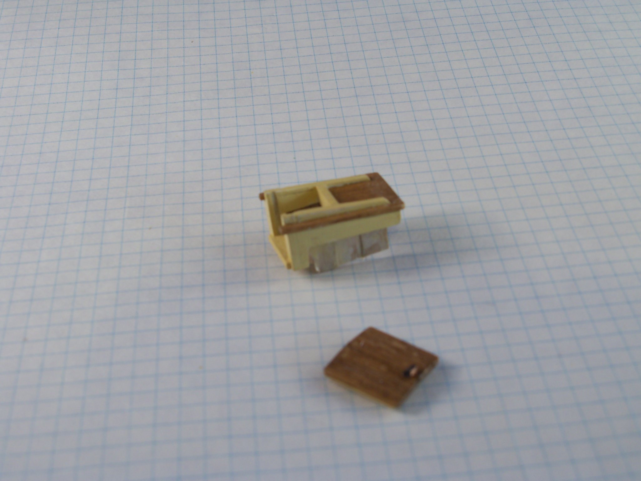
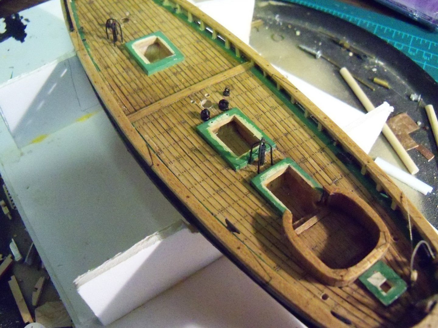
The fore companionway was next. Having the companionway hatches left open made everything much more involved as more of the insides would be visible and I needed to search quite a bit to find out what the inside even looked like. I tried to incorporate most of the details shown in the following sketch compiled from several illustrations from the internet. The side and closed end walls were made with 3/32” basswood with the end wall arched on the top for the roof. For the open end I took some 3/32” square basswood and routed a 1/32” center groove and glued it vertically to the front edge of the side panels for the pair of drop panel door slabs to slide into. I cut a piece of 3/32” basswood and glued the ends onto the sidewalls with an arch on top to match top of the end wall. This was for the roof support across the middle of the hatch opening to align with the water dam to support the cut off roof boards. At this point the assembly was painted light buff deck house and set aside while I worked on the sliding hatch cover. The 1/32” x 1/16” runners were tapered and a thin groove was cut along the top for the hatch slide anchors made with some thin shim brass. A pair of notches were cut into the inside face of the runners for removing the hatch cover and also notched for the dam. I even notched for the drain holes in the side runners by the dam. After cutting the dam to fit the resulting opening and gluing it between the runners, everything was painted light buff deck house. Now for the roof itself which was made similar to the skylight roof, but with a notch cut out for the roof hatch. One other difference in the roof was that rather than putting any end cap trim on the ends of the roof boards, they were run straight thru. Then of course it was finished similar to the deck boards. Once dry, the roof and runner assemblies were glued up with carpenters glue and set to dry. As you may have noticed by now, I am a strong believer in painting or finishing the individual pieces before assembly, which even at this small scale still allows a sharp division between the different finishes without masking. (I must admit that I got a bit carried away here, adding so many details that would not be visible on the finished model, but at least I know they are there.) While this portion was drying, I had to make the sliding hatch cover. Once again I glued narrow strips of 1/32” basswood over the cambered waxed form with filter paper. For the hatch cover I didn’t put finished trim pieces across the ends of the boards, I just trimmed them off square. This was then stained, finished and allowed to dry. Taking some 1/32” basswood strips that I sanded a camber on the top edge, cut these to length and notched the ends for the shim brass hatch slide anchors and attached them with AC glue. Now I used 2 strips of 1/32” square basswood to serve as the slide covers. All of these parts were then painted in light buff and glued onto the bottom of the hatch cover. A tiny bit of blackened copper was also glued on with AC to the top of the cover for the upper latch. As the companionways were to sit on top of the coamings, I made a sill stop of 1/64” basswood to sit on top of the coaming for the drop panels. The rear companionway was a little different than the one on the foredeck in that the open end had stepped down into the cockpit area, but otherwise was made similarly. Since there was no coaming inside the cockpit, I made a sill from 1/32” basswood with a 1/64” sill stop. Here are some photos below of the fore and aft companionways. The entrance doors for the companionways were made with two separate pieces: an upper and lower drop down panel. I made each of the door panels with two layers of 1/64” grooved plywood glued together with carpenters glue. On the outer face of the panel the grooves were run vertically and the inner face they were run horizontally. I cut the panels to size, leaving a 1/64” rabbet where the panels overlapped and an arch on the top edge of the upper panel to match the curve of the sliding hatch covers. These were stained, sealed and set aside for later installation. The following four photos are of the finished door panels. The first shows the outside faces, the second the inside faces, the third shows how they appear when joined together, and the final photo shows how I plan to display them by the forward companionway on the finished model. The cockpit walls were carefully cut and filed on the open end so the walls were able to terminate at the sides of the companionway walls. And finally, I cut and fit some of the 1/64” plywood to serve as the inside wall facing and at the same time serve as a guide to slip the companionways into their coamings. I still need to make the access ladders and decide how to finish the insides. If painted dark, it would hide most of the detail inside; while if painted a lighter finish I would need to see what other details would be visible. At this point I’m not sure, more internet searching may be needed here I guess. The deck houses and cockpit wall assemblies were all removed now and set aside at this point.