


allanyed
-
Posts
8,065 -
Joined
-
Last visited
Content Type
Profiles
Forums
Gallery
Events
Everything posted by allanyed
-
 Very nice work Rod! The stove mini kit is a gem but raises a question. In the Arming and Fitting of English Ships of War Lavery states that with the advent of iron stoves, they sat on a flat metal base, but this looks more like brick or stone work, thus my confusion. I realize very little is set in stone in shipbuilding in the days of sail and would not be surprised if one or the other or perhaps both types were used on various ships, but I am curious if there was a so called norm and if anyone knows of other sources of contemporary based information on this. Allan
- 78 replies
-
- 2
-

-
- Sphinx
- Vanguard Models
- (and 1 more)
-
Something modern such as the latest Auld Mug winners including the New Zealand Te Rehutai (Sea Spray) in the photo below. Then again, these may be better suited to plastic. It might be very interesting to have a model of America 1851 and Te Rehutai on display side by side. Video below is really interesting --- 50 knots in a sail boat!!!! Allan

-
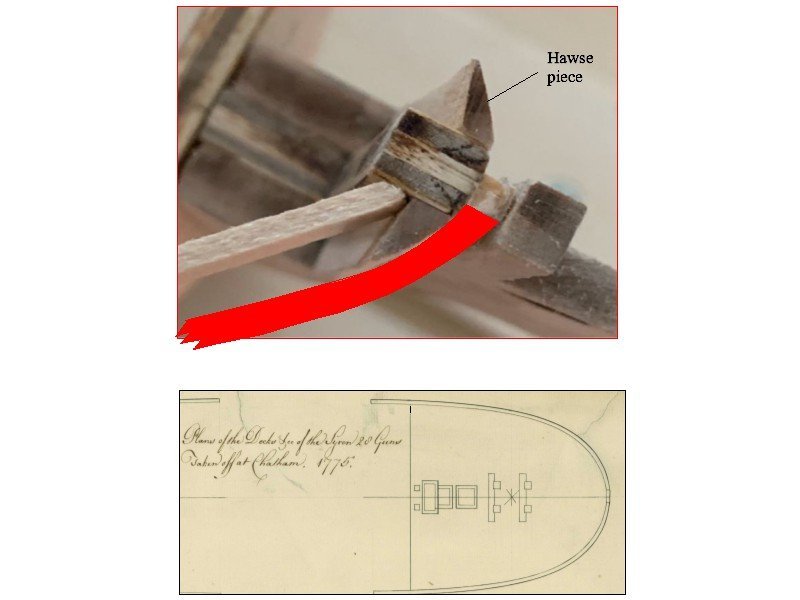
Big OOOPS on my part Chuck.😁 I really should have thought about that possibility. What threw me though was the plank(?) in the second photo which is inside the hawse piece. Allan
-
Shipfic A warm welcome to MSW. It would be nice if you posted a little intro in the new member forum with a little about yourself. Again. welcome to this motely crew. Allan
-
What have I done wrong
allanyed replied to Dindsy's topic in Building, Framing, Planking and plating a ships hull and deck
I am not sure you have done anything wrong yourself. Regarding the frames and deck beams (ribs and spars😀), while the decks were almost horizontal midships in many cases there was often some curvature. Looking at the kit, which is purportedly 16th century design, there are a number of inaccuracies so it MAY be the kit designer got it wrong. For example, there are belaying pins which were not used until two centuries later. Instead of triangular or heart shaped deadeyes there are round deadeyes which did not come into use until much later. The carriages have four trucks (wheels) where as they were usually equipped with two trucks and a sled at that time. No matter. it is part of the learning curve and the main thing is have fun while learning the intricacies which just takes time to do some research along the way. Allan -
3D Printing Cannons in Resin
allanyed replied to thibaultron's topic in 3D-Printing and Laser-Cutting.
Hi Srenner I think Greyhound (20) 1720 carried 6 pounders, probably Borgard pattern, which were issued on new ships from 1716-1724. Is there a reason you want to mount 18 pounders on such a small ship? Allan -
3D Printing Cannons in Resin
allanyed replied to thibaultron's topic in 3D-Printing and Laser-Cutting.
Hi Srenner, Is this for your Greyhound (20) 1720 build? Allan -
Hi Paul, I may be completely misunderstanding your problem, but here goes. When you say battens, are you referring to the hull planking? Looking at the contemporary drawings of the Syren at RMG the angle of the plank that you show looks to be too sharp. but the piece that looks to represent a hawse piece looks right. If that is the case, the plank needs to be bent more to give the bluff bow appearance called for in the original drawings (the red strake below.) See sketch below. For the contemporary drawings go to https://www.rmg.co.uk/collections/objects/rmgc-object-83191 at RMG, (low resolution) or https://commons.wikimedia.org/w/index.php?title=Category:Ship_plans_of_the_Royal_Museums_Greenwich&filefrom=Sail+plan+for+18-gun+Brigs+RMG+J0057.png#/media/File:Siren-Syren_(1773)_RMG_J6306.png for a high res version on the Wiki site. Check the shape of the bow at the forecastle to see what I mean. This drawing was taken off the ship after she was launched so is more of an as built thus very accurate. Again, I may be completely misunderstanding your problem, so apologies if this confuses things. Allan
-
Is there a reason you did not taper the planks so they end at the rabbet? They were pretty much done as the ship planking and would be much easier to get in place. Chuck Passaro’s four part video on planking on You tube is a huge help. Allan
-
I take that as a compliment but I rarely have the answers. I do have a decent library and enjoy doing the research though. When research fails my go to folks are mostly members here at MSW including Druxey, Ed Tosti, Mark Porter, and a host of other experts who have taught me so much over the years as they know far more than I do. Regarding belaying pins for British warships, James Lees gives 1745 as the approximate time belaying pins came into use in the RN. Did this apply to merchant ships such as the Mayflower? I would think that is the case, but maybe they were ahead of their time. Study photos of contemporary rigged models at RMG, Preble Hall and elsewhere and you will see the rigging terminating at rails, not pins on models made prior to 1745. Were there exceptions? Maybe, there was a lot of variation in the early days, especially in rigging. The below are a couple shots of early 18th century ship models (1705 and 1714) taken during a visit to Preble Hall. Allan
1714.thumb.JPG.a4b9a45c318862f5a7856580b5a1cbc4.JPG)
-
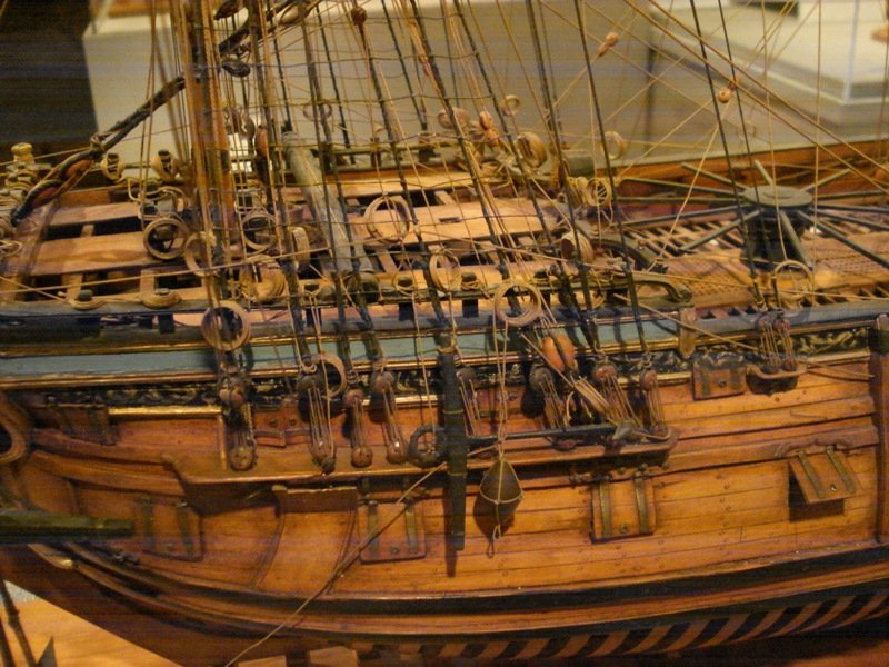
Nice start on the construction Rick! From the second photo it looks there are belaying pins in the kit. The British did not use them on navy ships until about 1745 so, to me at least, it seems odd that they would be in use on the Mayflower more than 100 years earlier. 🤔 Allan
-
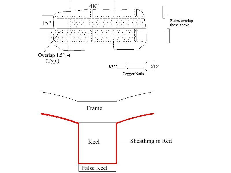
It appears that the copper is covering both the area of the keel and false keel. There has been a good bit of discussion the past few days at https://modelshipworld.com/topic/36042-copper-plate-overlapping-1794-lower-overlaps-upper-or-vice-versa/ that some may find interesting that indicate the copper did not cover the false keel. Sketch below of the overlap &c. Allan
- 49 replies
-
- 1
-
-
- Pegasus
- Victory Models
- (and 1 more)
-
Yep, gun ports and lids take some work as each is made of about 6 pieces of wood, 3 port lining pieces, hinges, nails, rings, rigging line, metal leads through the hull, all told, about 25 individual pieces to each. Plus there were ventilation ports with small lids on some of the gun port lids on the lower decks on later ships-of-the-line. Allan
-
You may be right, but if it's sacrificial, why waste the copper? Also, there is no mention of coppering the false keel in the contracts mentioned in post #9, only that there is copper between the false keel and keel which is turned up. Still, all new for me so a good day!! Allan
-
Very nice!!! You are a big step ahead of most, if not all kit designers and modelers. Allan,
-
We are all here to help each other Paul, glad to be of at least a little help. Cheers Allan
-
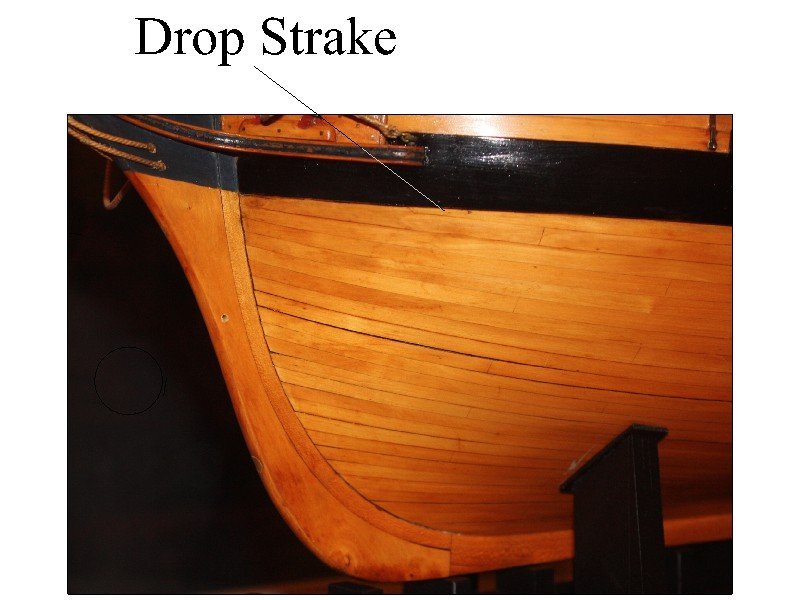
Just as a helpful hint for the future, with the exception of a drop strake, all strakes seat into the rabbet at the bow. They are usually tapered and never come to a point. If there is to be a drop plank it is snubbed on the end rather being pointed. (see below) Of course, if the hull is painted or coppered, this is not so noticeable. It is a shame that some, NOT all, kit makers completely fail in this area. Allan
-
Paul, The link is https://modelshipworld.com/topic/3453-young-america-by-edt-finished-extreme-clipper-1853/#comment-96388 or you can go to the search box and type in Young America. Once you open it the rigging is far down in the topic (after page 100) Allan
-
Sizzolo Thanks for the source. Now, I wonder if any modelers coppering the bottom will be reading this string of posts and show the false keel outside the sheathing on the keel itself. I read the paragraph just now and I do wonder what he means that the false keel was filled with small nails. Is it heavily nailed like hob nailed boot soles or something else? For our purposes these would not be seen anyway, but I am curious. Allan
-
PaulRon I just looked at Ed Tosti's build log and he does go into detail about lines passing through fairleads in the tops and shrouds. Allan
-
Paul Ron Have you studied Ed Tosti's Young America build log? Not sure, but it may be of some help to you. If not, his Young America 1853 Volume III on rigging probably will give some help to you. Allan
-
FWIW, below is the overlap as drawn by Peter Goodwin in The Construction and Fitting of English Man of War, pp 225-26. He does show the plating overlap the strake above. Allan
-
Did a little more digging and found the following in contracts for the Echo (1782) , Aurora (1776), and Astrea (1808) which I thought was very interesting. I do not recall ever seeing this on a model where the coppering is done on the keel before the false keel is secured to the bottom of the keel. It makes total sense as the false keel is sacrificial so why protect it as well as prevent it from doing its job. Allan As the Ship is to be partly coppered before the False Keel is put under, Care must be taken that there is Copper, as shall be directed, put all Fore and Aft between the Main and False Keels, properly turned up and fastened.
-
It is indeed difficult to tell in the video, but the photo below of the Constitution bottom SEEMS to be shingled with upper over lower. Allan

-
A very warm welcome to you Mark, very nice intro. Allan

1714.JPG.d37b5a6e235c6c635153281318d513a6.JPG)
