


allanyed
-
Posts
8,149 -
Joined
-
Last visited
Content Type
Profiles
Forums
Gallery
Events
Everything posted by allanyed
-
 Ras, This topic has not had an entry in four months so may not get fast or many responses. You might want to consider PMing Greg, who started this topic, for contact information. Allan
 -
HMS Victory belaying anomalies
allanyed replied to tedrobinson2000's topic in Masting, rigging and sails
Ted, The following is from Lees' Masting and Rigging of English Ships of War. From the 1733 Establishment, the fore topsail yard braces on a first rate belayed to cleats on the bulwarks just aft of halfway between the fore and main masts. Once the gangways and skids came into use, this would not work. By 1742, the fore topsail yard braces were being belayed to the forecastle rails but not on the belfry itself. About 1805 the fore topsail yard braces were belayed at the main jeer bitt. Note that the location of the standing parts and blocks were in slightly different positions on the main stay for each period as well. Allan -
Or a rubber band around the self closing tweezers. As to replacing two or three blocks, it would probably be easier to make your own. Good practice for future work 😀 Allan
-
Hi Jim, I see where Lees describes the brails on either side of the sail and he also states that the brails all went on both sides of the sail on page 109 for the lateen type sail, but I cannot find where he mentions anything about this for the spanker. He does go into some good detail on the peak, middle, throat and foot brails for the spanker on page 114. Hi Tom, On page 179 Lees gives belaying points for all of the spanker brails for a frigate of 1810 but I have no idea if this would be similar for Leopard. Could be that these are not appropriate for a 50 gun ship of 1776 just as Petersson's book may not be appropriate for every line as his book was based on one model of a 32 gun ship of 1785. Still, together, they may be of some good help. I checked Steel's Elements and Practice of Rigging and Seamanship, but he does not even mention the brails for the spanker that I could find. https://maritime.org/doc/steel/part7.htm#pg217 Allan
-
Chain Plates Gor 16th Century Spanish Galleons
allanyed replied to Bill Jackson's topic in Masting, rigging and sails
Steven, I looked at the collection. WELL DONE piece of work!!! Allan -
Luigi, Where are you located? With experienced builders all over the world, MAYBE there is a member near you that can help. Even if there is not someone that you can meet with in person, a Zoom or Skype tutorial may be possible. Ciao Allan
-
HMS Victory belaying anomalies
allanyed replied to tedrobinson2000's topic in Masting, rigging and sails
Ted, I have never seen a contemporary instruction on how to tie a line to the rail, but maybe the close up below of lines tied to the rails will help. I doubt this would be appropriate by 1805 though what with belaying pins and timberheads available. Keep in mind even though this is a contemporary model at Preble Hall, it may have been re-rigged at some point although they are likely to be accurate. I looked at a bunch of photos in John Franklin's book and Lees' but cannot find very clear closeups that show how these were actually tied. That they were tied in some fashion to the rails I have no doubt, but as to the method, I have not been able to find anything so far. Regarding the weight of the fore yard, I am coming up with something much less. Assuming a length of 89' 1" and diameter20 7/8" (Lees' Masting and Rigging page 198 specifically for Victory) and a taper that left an AVERAGE diameter of about 16 inches for the entire yard, a weight of about 45 pounds per cubic foot for dry oak (https://www.oocities.org/steamgen/woodweights.pdf) (Fir looks to be lighter) I come up with 16X3.14X1069= 53,706 cubic inches. 53,706/1728 cubic inches per cubic foot =31 cubic feet. 31X45=1,395 pounds. I am no math teacher so my numbers may be bogus but there is a big difference with our numbers. From Lees's Masting and Rigging page 64 ---- The fore yard had two sets of jeer blocks. For each set, the upper block was treble sheaved and hung from the mast head with a long strop. The yard had two double blocks, (one to go with each treble block) strapped to it at the slings. I cannot find any information where and how the line was stowed, other than contemporary models that show the lines in large coils at the foot of the bitts. Again, hope this helps. Allan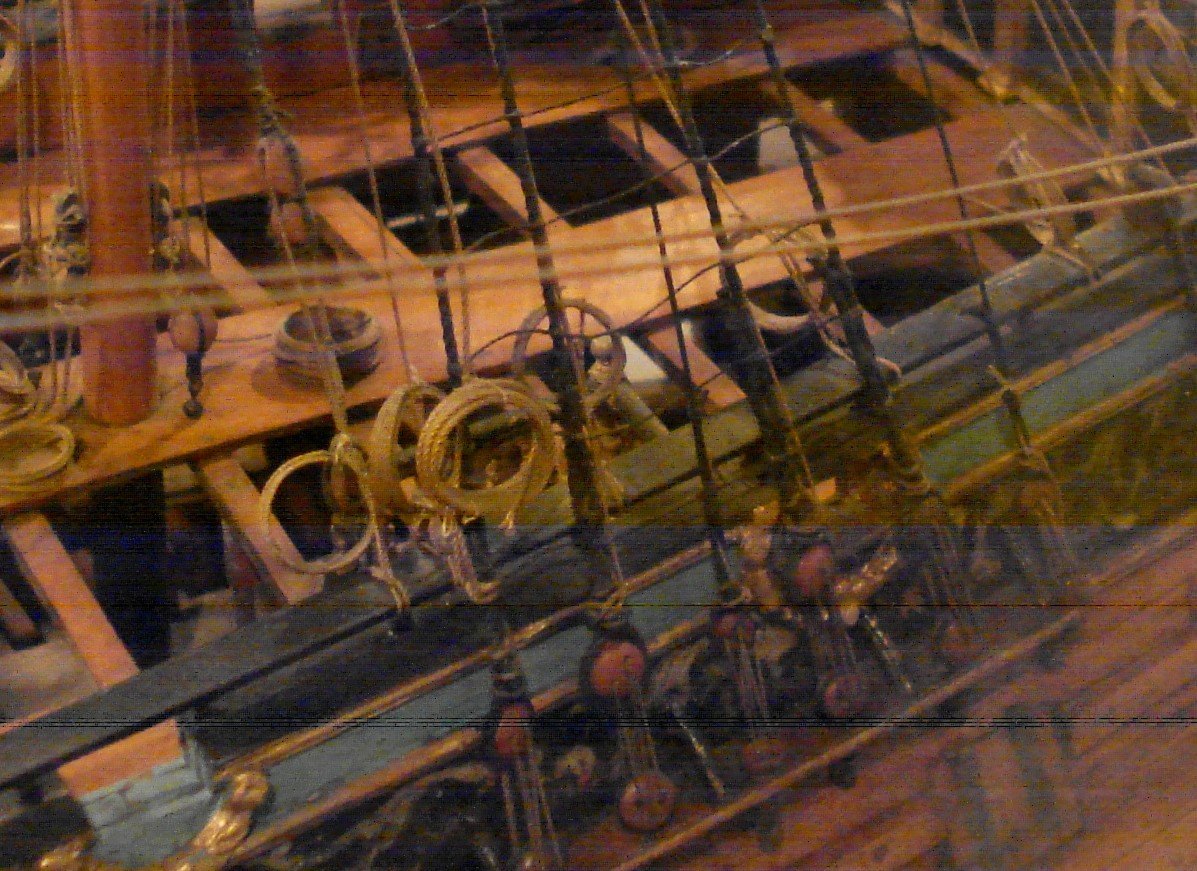
-
Olha, Love your work and lessons!! Taking a wild guess here but are you related to Kroum? I figured that might be the case as he is with UConn and a marine archeologist. I still reference his thesis from A&M once in a while!! Allan
-
Stunning workmanship and very nice photography. Allan
-
HMS Victory belaying anomalies
allanyed replied to tedrobinson2000's topic in Masting, rigging and sails
Hi Ted, In The Anatomy of Nelson's Ships by C.N. Longridge, he points out that the book is based on authentic and accurate drawings. Going with that supposition, you can use pages 264-272 which describe and/or show the belaying points for Victory. He does state that he did not rig every line on his own model, which I believe is still at RMG or another British museum, but he does give what seems to be most, if not all, belaying points. Note that there is not always just one line on a single belaying point. As an example he points out that the Admiralty drawings show the eight timberheads on the rail at the beakhead receiving about three lines on each timberhead. The book has several diagrams and several lists with the names of each line and their belaying points. Can't copy these diagrams and lists here due to copyright issues, but the information should be extremely useful to you. There are used copies of this book for less than $25. https://www.thriftbooks.com/w/the-anatomy-of-nelsons-ships_c-nepean-longridge/502417/item/13222021/?gclid=CjwKCAjwmqKJBhAWEiwAMvGt6GJSVfkrD7oa0AsbylrQC9zqMPBbeoxaxxJ6ElXA-cyGJDaZ_9zWrxoCg-gQAvD_BwE#idiq=13222021&edition=3404533 is one example. Looking at contemporary drawings circa 1765 and a model of Victory from the early 19th century at RMG Collections, there are indeed 11 timberheads on each side of the forecastle. https://collections.rmg.co.uk/collections/objects/79912.html Anyone building Victory would be well served to have the Longridge book as a reference. You mention lines being tied to the rails themselves. This was common on 17th century ships and into the early 18th century as there were few if any timberheads like those found later on. I do not recall seeing this practice in later years either on contemporary drawings or models. Hope this helps!! Allan -
How to seize a block to an iron band
allanyed replied to Laggard's topic in Masting, rigging and sails
Well said Phil!!!! Much more astute and mature than the sarcasm and name calling (rivet counters) others have shared with us. Allan (A happy rivet counter) -
How to seize a block to an iron band
allanyed replied to Laggard's topic in Masting, rigging and sails
The era matters and the scantlings from The Elements and Practice of Rigging and Seamanship by Steel (London 1794) may not be apropos, but lacking other information more contemporary to 1742, these may be at least a little bit useful. These scantlings and tackle descriptions, including if there is a hook and eye, single, double or other type block, traveler, heart and thimble, &c. can also be found on pages 98-101 of W.E. Mays' book Boats of Men of War which he acknowledges came from Steel. Looking for earlier similarly detailed sources, but not coming up with anything so far. Allan -
How to seize a block to an iron band
allanyed replied to Laggard's topic in Masting, rigging and sails
Just a thought here, not looking to poke or provoke anyone. Love the boat picture from RMG that was posted above which I think comes from (https://collections.rmg.co.uk/collections/objects/66291.html) But, while it is contemporary, has it gone through modern renovation like many models that old. RMG does not usually give those details, only the original date a model was probably built. Rigging for example on a 260 year old model may not be original. If it is original , I would love to learn more about what material was used and how it has been preserved for nearly three centuries. Cheers guys, Allan -
How to seize a block to an iron band
allanyed replied to Laggard's topic in Masting, rigging and sails
Laggard Wefalck makes some excellent points and is giving good advice. As to making hooks, they are not that hard to make. Do a search here at MSW. One example is below which references tutorials as well. Allan -
Thanks for the link Rich!!! I checked out the website but could not find many of the tight grained woods popular for ship models such as pear, castello, European box, holly, apple, and Alaskan cedar. Do you know if they have these species? (They do have paper backed pear veneer at $705 plus shipping for a 4X8 rolled up sheet) Also the search function does not work. I typed in apple and the results were lots of species from alder to white oak but no apple. Allan
-
Photoetch brass black problems
allanyed replied to Seems ok to me's topic in Metal Work, Soldering and Metal Fittings
These erasers may work, but personally I have never found a better system than the one described by Greg at https://modelshipworld.com/topic/21710-blackening-revisited/?tab=comments#comment-651453 It is a fail safe method. The pickling will give you the "rough" clean surface. An eraser like you describe by itself probably will not work without pickling so may as well skip the eraser as it will not add any advantage to this system. The only problem in the write up is I that I have not been able to find Blacken It for a couple years as I am pretty sure it is no longer available. Birchwood Casey is probably the next best solution to use, although I find a dilution of about 3 or 4 to 1 works better than 7 to 1 for this particular product. Allan -
Understanding Truss Pendants and other rigging things
allanyed replied to LucienL's topic in Masting, rigging and sails
If you are speaking about the single pendant and falls shown in the Peterssen drawing for the crossjack, from what I could find there should only be one fall as shown, not a pair of them. The Monfeld drawing for the lower yards (not the crossjack) matches Lees. From about 1806 to the end of the sail period, the topsail yards and the topgallant yards truss parrels were set up differently and had no falls at all. The topgallant truss parrel was sometimes set up the same as the topsail yard truss parrel, or sometimes with two strops, but again, there were no falls. Detailed drawings and written descriptions can be found on pages 84 and 95 in Lees' Masting and Rigging. Too much to copy here without violating copyrights, but perhaps someone has redrawn these and can post. Allan -
Phil, I took a look at MM as I was curious about these. Thanks for posting this. I am sure they would look great for a house or a building which had stairs instead of ladders. I think wooden ships always had ladders with side rails rather than stairs with stringers. I may very well be dead wrong, but I have not been able to find stairs on any contemporary ship drawings or models, just ladders. Allan
-
Understanding Truss Pendants and other rigging things
allanyed replied to LucienL's topic in Masting, rigging and sails
Hi Lucien, Truss pendants and falls replaced parrels and sometimes were actually called truss parrels. It holds the yard to the mast just as the parrels did. They moved up and down when the yards were moved up and down. I THINK the falls of the truss pendants were to move the truss with the yard more than to lift or lower the yard itself which I believe was the job of jeers or ties. The Zu Monfeld drawing shows pendants as they were from 1760 to 1810. From 1810 to 1850, (according to Lees) the pendants rove UP towards the after end of the trestle trees where there were a series of block connected to eyebolts hanging from the trestle trees. The Peterssen drawing matches that of Lees for the Cro'jack. The falls in the Monfeld drawing are not dangling, they just don't show the series of blocks that were part of the falls rigging. Allan -
Bronko Welcome to MSW. You posted the second video here but it shows this is your first post so the first video is missing.
-
Eberhard, I found this website. https://www.turbocarver.com/ Looks like a compressed air driven version of a Foredom et al. Allan
-
The techniques in the video of setting up the breeching rope rings and eyebolts look to be very useful. At these small scales the loop for the cascabel is not unreasonable as making a proper cont splice is not so easy at the smaller scales. Unfortunately the running out and training tackle is wrong as she neglected to include the hooks on the ends that go into the eyes. I am not so sure her methods would work if she included the missing hooks. We see Flemish coils on a lot of models modern as they are so visible, but I wonder as to the accuracy of using them. I have searched, without success so far, for contemporary evidence that Flemish coils were used in place of frapped lines. If anyone can share any information based on contemporary sources about the use of these coils that would be great. I have seen stacked rope coils for other running rigging, but no Flemish coils for the 17th-19th centuries so far. Allan
-
NAIAD 1797 by Bitao - 1:60
allanyed replied to Bitao's topic in - Build logs for subjects built 1751 - 1800
This build is a joy to follow! I am watching your setups on the mill as I am in the very beginnings of learning how to make the most of using one. In addition your setups on the building board are well thought out. Lots of gizmos that should be on my Christmas list!!!! Allan -
A good day as I learned something new in that I never knew yards were stored on the channels and I would like to learn more about this. AH, can you share any contemporary information about this stowage on the channels, how they were secured, etc. I am having a hard time picturing this as the lower yards on the USS Constitution were nearly triple the length of the channels. I did some searching on my own but could not find anything contemporary. I did find a very nice, well detailed, set of free plans at https://ussconstitutionmuseum.org/discover-learn/modeler-resources/ The ship's boats drawings are especially well done. Jackstays were introduced in the Royal Navy in 1811 so if the US was copying the idea, makes sense that they probably had not knocked off the idea by 1812. Do you know when jackstays came into use in the US? TIA Allan
-
Kirby, After looking at your progress, for a first build, or even had this been a third or fourth, you should be proud of how good she looks. This is not on you, but it is such a shame that so many kits supply wood like walnut that looks totally unrealistic due to the huge grain. In one of your April posts, you wetted and sorted the walnut planking by color and grain which is a great idea, especially for the colors. But at our scales there should be no visible grain at all. If you go with another kit after this build, vet the kits you are considering, BUT.... you sure appear to have the skills, so maybe a scratch build is in your future!! It opens a whole world of choices with many hundreds of detailed contemporary plans available from which to choose. Allan
