allanyed
-
Posts
8,149 -
Joined
-
Last visited
Content Type
Profiles
Forums
Gallery
Events
Everything posted by allanyed
-
 Vahur Try https://www.gilmerwood.com/search/results?utf8=✓&q=holly They are a great supplier. Can't speak for pricing with overseas shipments though. Head päeva Allan
 -
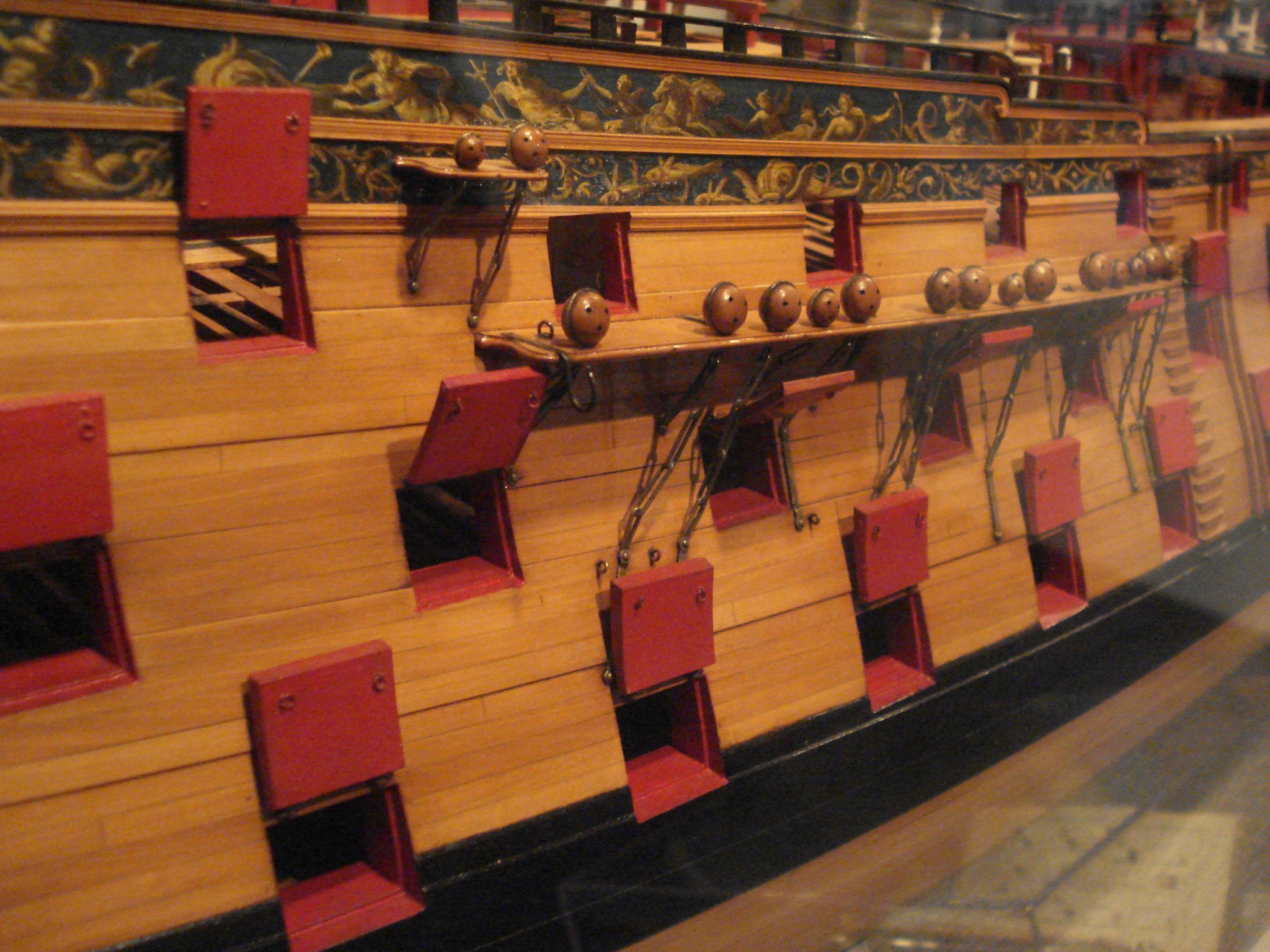
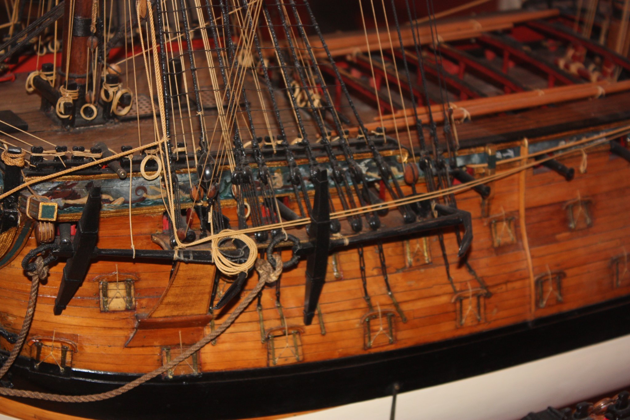
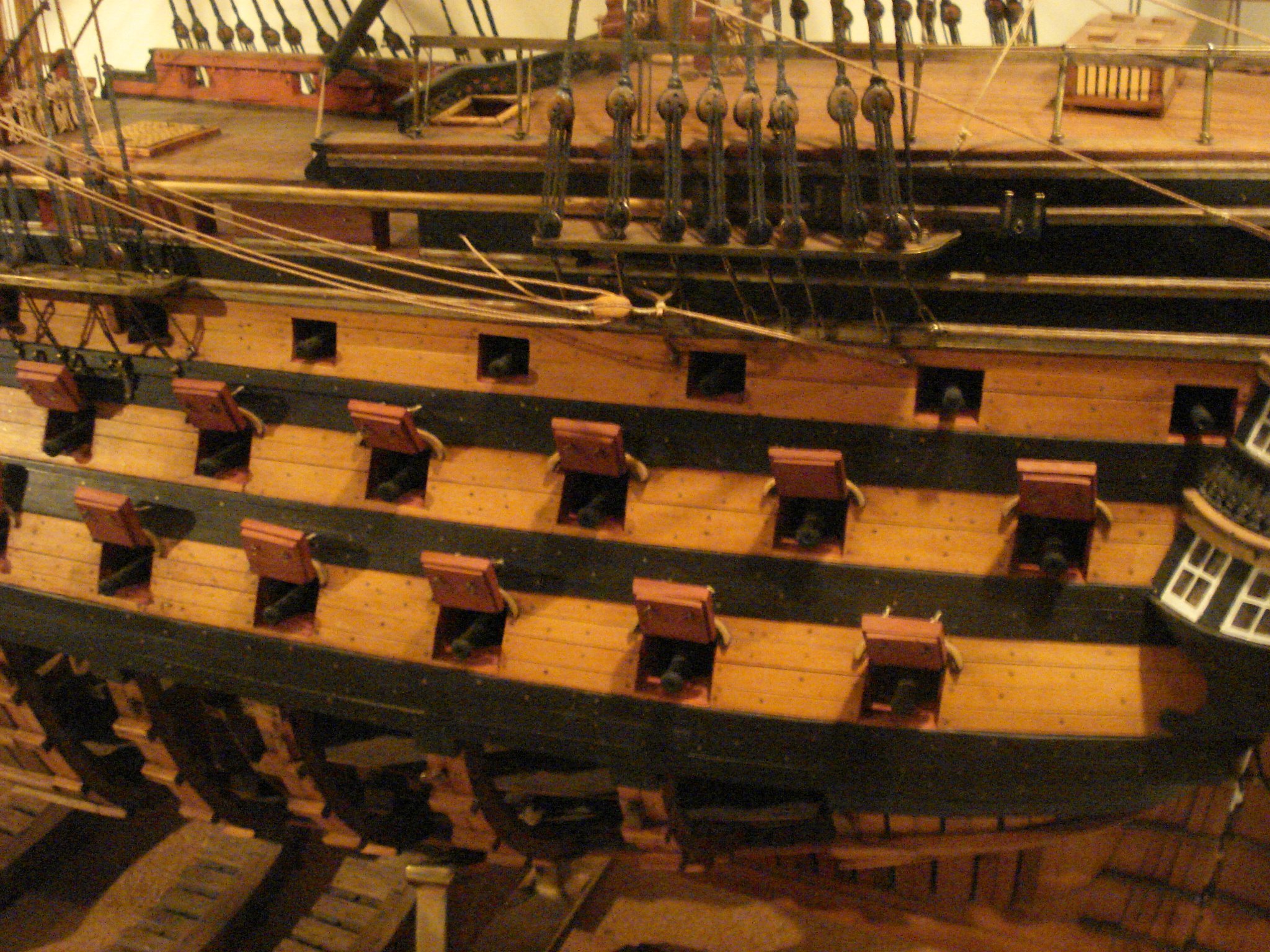
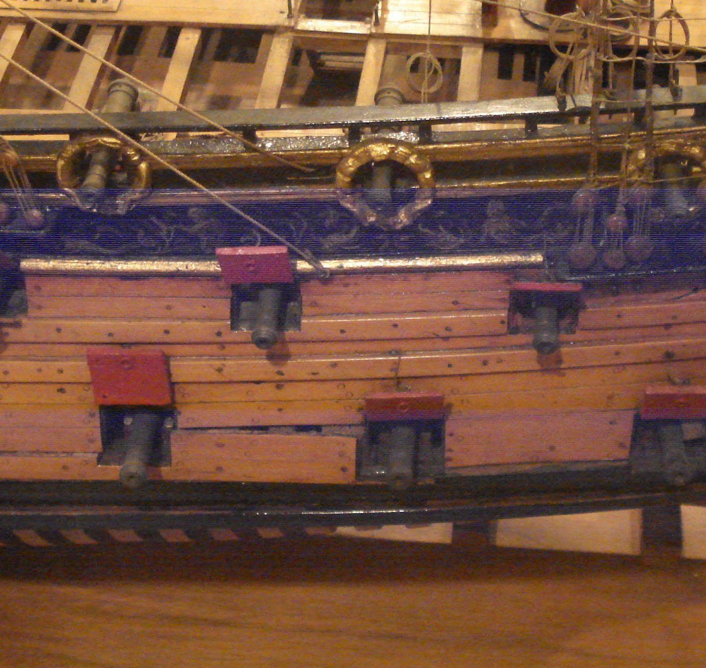
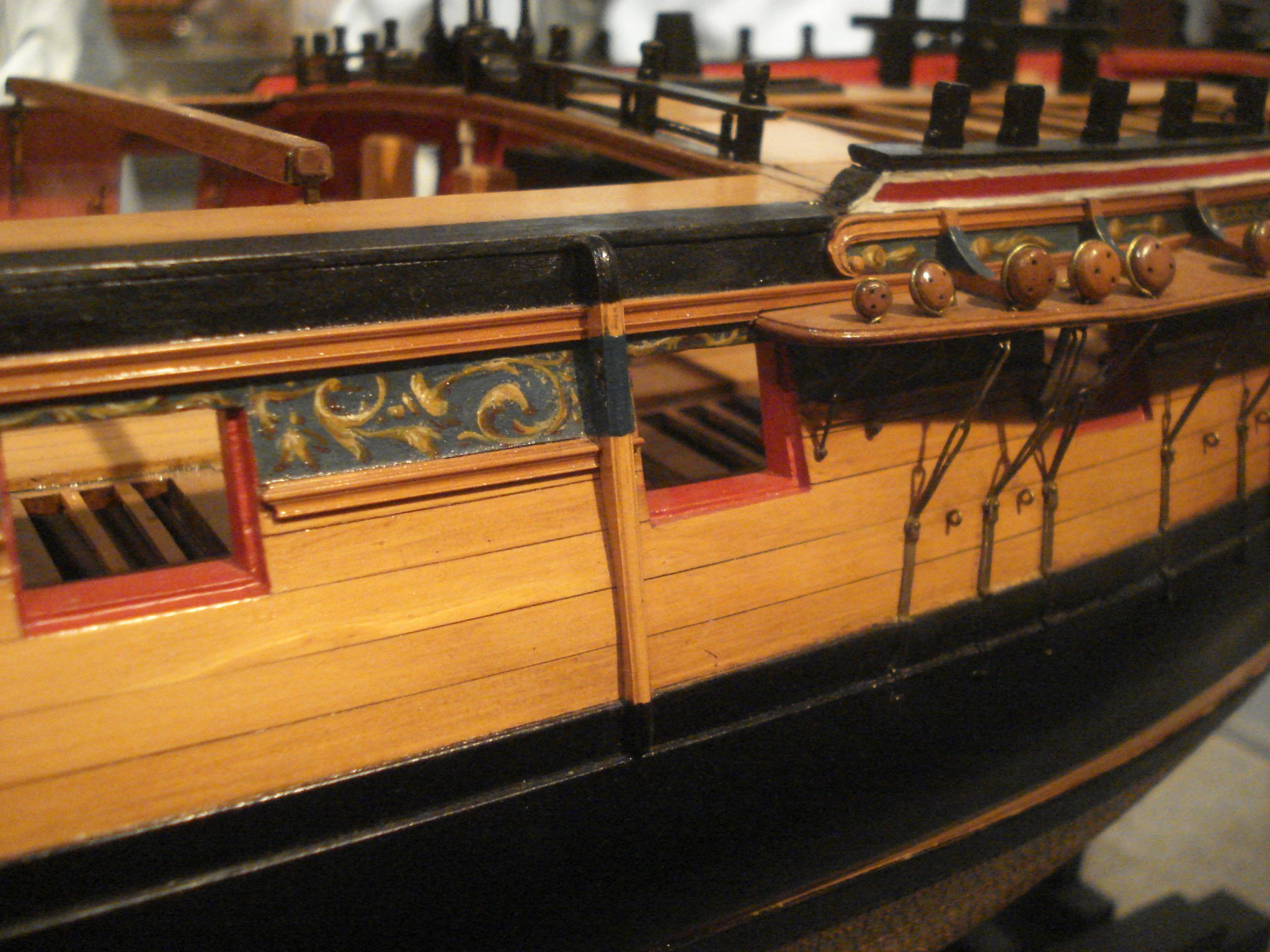
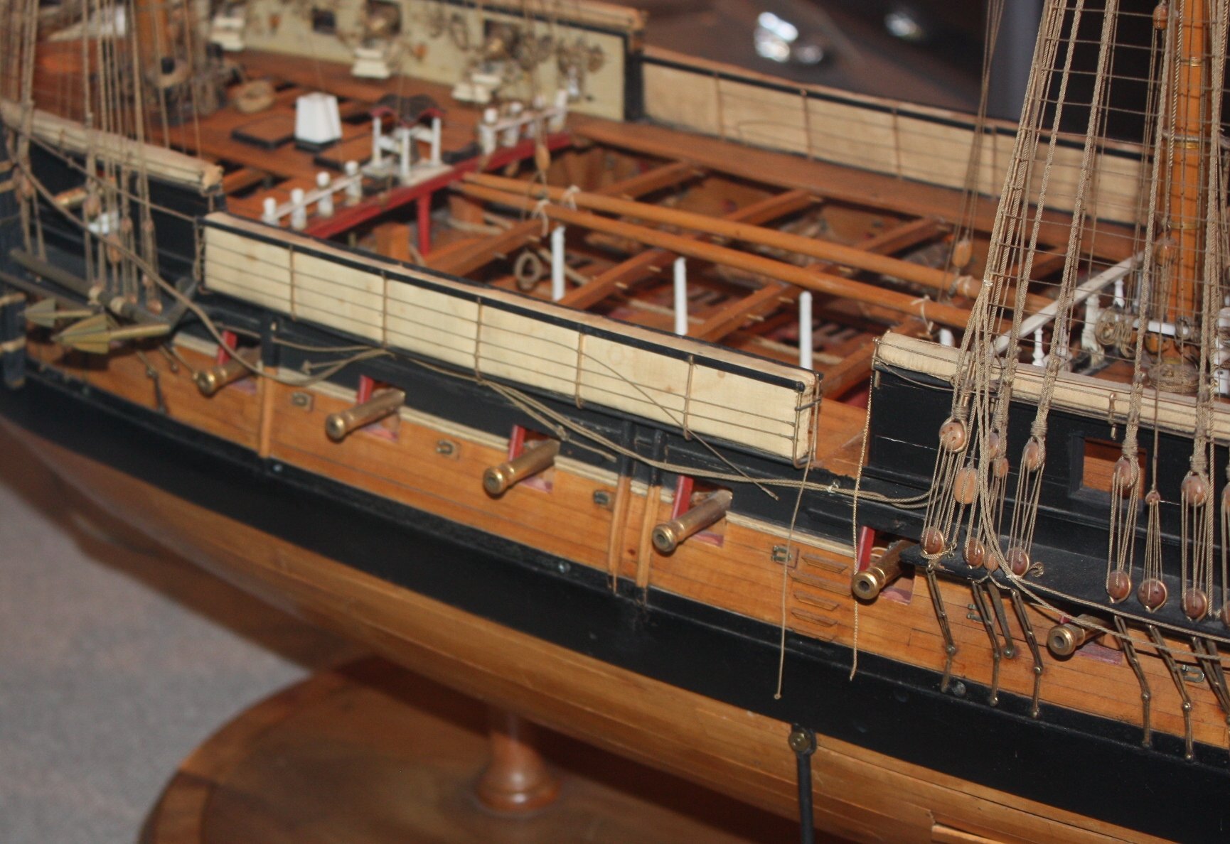
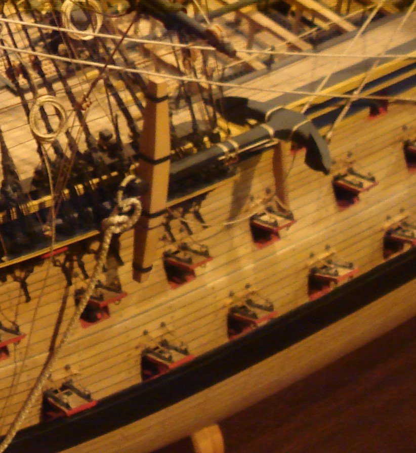
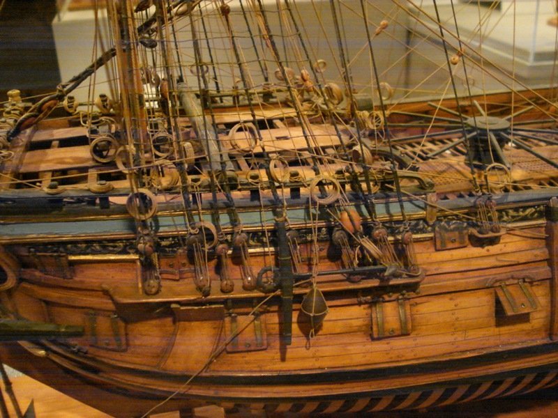
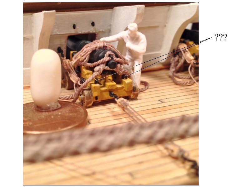
Ian, the number of ropes on a lid depends on the ship and era and possibly the size/wieght of the ports. For opening, some had two rings and ropes that came to a single pulling rope, and of course many had two independent ropes for opening. For closing some had one rope and ring, some had two. The first photo is not too clear but you can see two ropes for opening and one ring for the closing. I agree with Jacek that the inside rope would not be rigged when the port is open as it would be something else to get in the way of working the guns. The first photo is blurry with zooming in but you can see a single ring for closing the port and two lines for opening. The second photo is pretty clear in that there is a single ring for the opening rope. The third shows two rings for the rope to pull the port closed. The last shows two rings and ropes made into a single going through the hull. Lots of choices, depending on the ship. Allan


-
I hope you know how lucky you are. With your supply you could plank a hull. What a beautiful color that would be!!! Allan
- 1 reply
-
- 4
-

-

-
Jaager You may be right but I would be disappointed to learn that the old model makers were lazy and took short cuts in this manner. As the lids are all painted, possibly we just cannot see that there are two layers. Sorry for the quality of the third photo. There are lips on these ports on the sides and top if I remember correctly same as the other models created by the linings. I did find a French contemporary model, the Ville de Paris which has lids with the inner layer smaller than the outer layer, but so far I cannot find any British models with this construction. Photo of her ports is below. I checked another dozen or so contemporary models and the lids were all constructed with the inner and outer layers being the same outside dimensions. As you said earlier, if the ports are closed, the construction style you decide to go with will not be seen 😀. You mention a thin layer over the end grains. Which photo/drawing is this? I looked in Goodwin and cannot find this. THANKS Allan
-
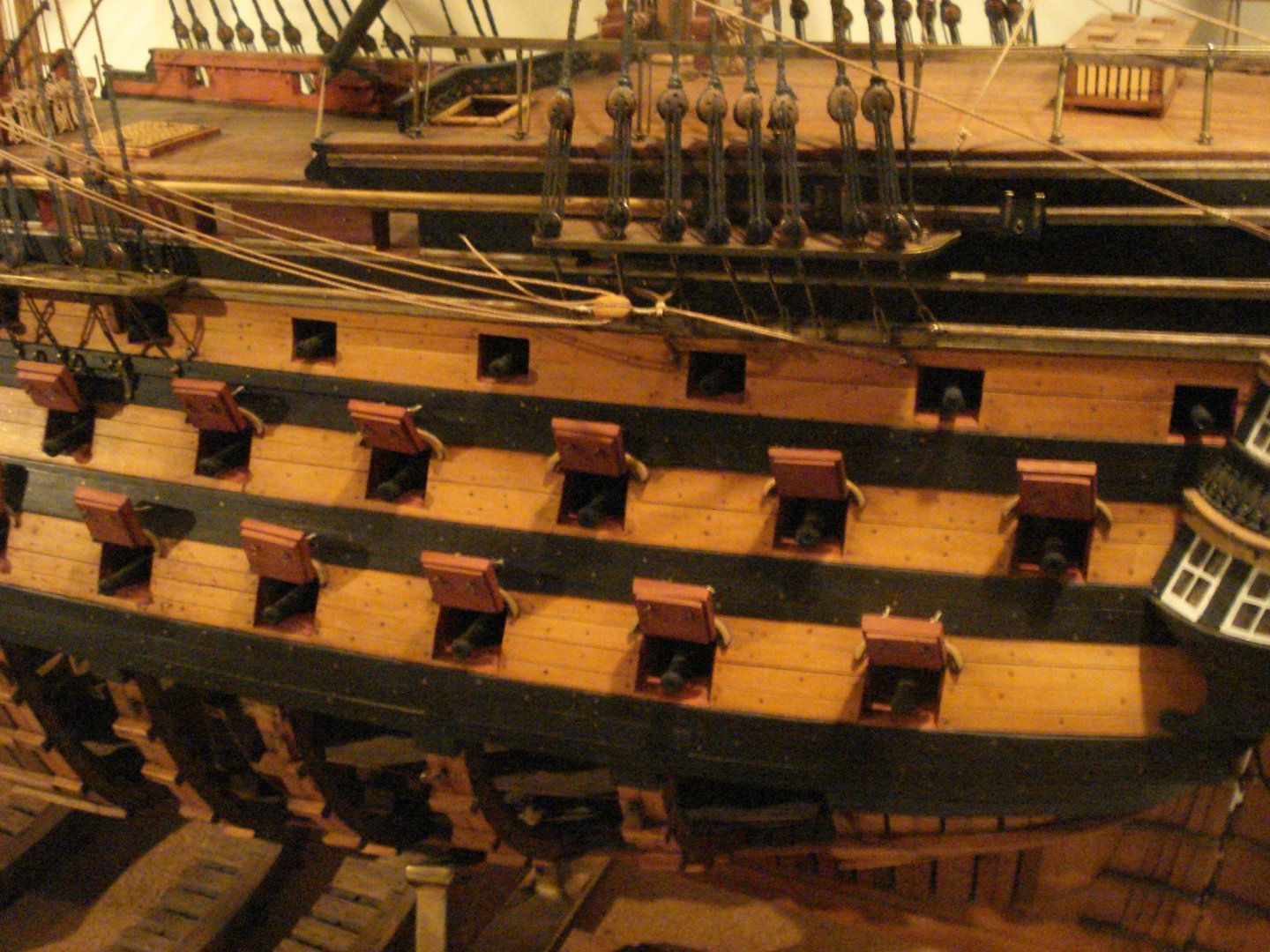
Jaager It is the inside the port - of the sill - at frame level - raised - not flush with the outside planking level- I must be a bit dense tonight as I cannot figure, for sure, what you are describing. I am sure it is just me so sorry about that 🙃. Can you perhaps post a picture? Reading Goodwin's comment on page 188 in The Construction and Fitting he indeed calls for the inner layer of wood to be smaller than the outside of the port lid, with the outside matching the thickness of the planking but I cannot find any photos of contemporary models with this kind of construction. To the contrary, all of the photos I can find show the lid total thickness with both layers of wood is the same as that of the planking. Additional photos from Preble Hall follow. I think Goodwin is a VERY important work, but as with any "modern" book, it is usually a good idea to research contemporary sources IF available to confirm anything. It could very well be that both styles of construction were used at some points in time. I would love to see contemporary information and/or models showing the lids as Goodwin describes as I have used Goodwin's description in at least one previous build. Allan ]

-
Hi Brian, I have a four piece set of steel machinest squares and use all of them on every build, so yes, I think these are a good investment. I use them on fully framed models and bulkhead type framing as well. Worst case, I would get a small one and a large one with the latter being at least as high as the cap rail from the building board. Even with the square, be sure your building board is true in all directions. For really small items and spaces, Lego blocks form the grandkids work very well for me, thanks to a tip somewhere here on MSW in the past year or two. Allan
-
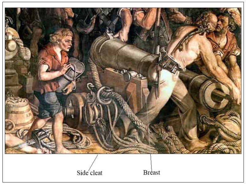
I just noticed something on the painting I posted above which gives me pause. There is a double block hooked to the carriage which means there is a double block at the bulkhead as well, but even then it appears that the line starts at the double on the carriage. This would have the loose end coming from this block which would be in the wrong direction. From everything I have found to date, there were never two double blocks, even on 32's which were the largest guns on Victory. So much for accuracy on this painting (which was done quite a few years after Trafalgar)
-
Jaager Not sure exactly what you mean. A drawing would help. In the meantime 😀................ The lid is two layers, one horizontal, one vertical. Total thickness of the two layers matches the thickness of the outboard planking so when it is closed and rests against the stops on the sides and bottom of the port the outside of the lid is flush with the surrounding planking. Unless the side of the hull is perfectly vertical the bottom of the lid has a slight bevel to match up the opening. The top of the bottom sills are not visible whether the lid is open or closed as there is a stopper piece. The bottom of the upper sill can be seen as there is no stopper piece. The outboard sides of all the sills are covered with the hull planking. Hope the following photo of a contemporary model in the Rogers collection will help a bit. TFFM Volume II has excellent drawings and description of the port lids &c. Allan

-
Thanks Gerard!!
-
Gary, Yes the frontal breasts and side cleats are clearly described by Caruana in volume II and would have been in use at the time of Trafalgar and evident on the famous painting of Victory. See pic below. Also, you can see these on the Congreve drawing in my earlier post above. These came into use about 1790s so could be appropriate for Victory in 1805. Dafi, Still living and learning on my part, so thank you very much for your reply, it is very much appreciated. Allan
-
Gerard, Yes I think everyone agrees that the item is a traverse board, but where does the name come from? Louis Renard makes more sense than a fox if he is the one who developed/promoted it in the Atlas de la Navigation. Allan
-
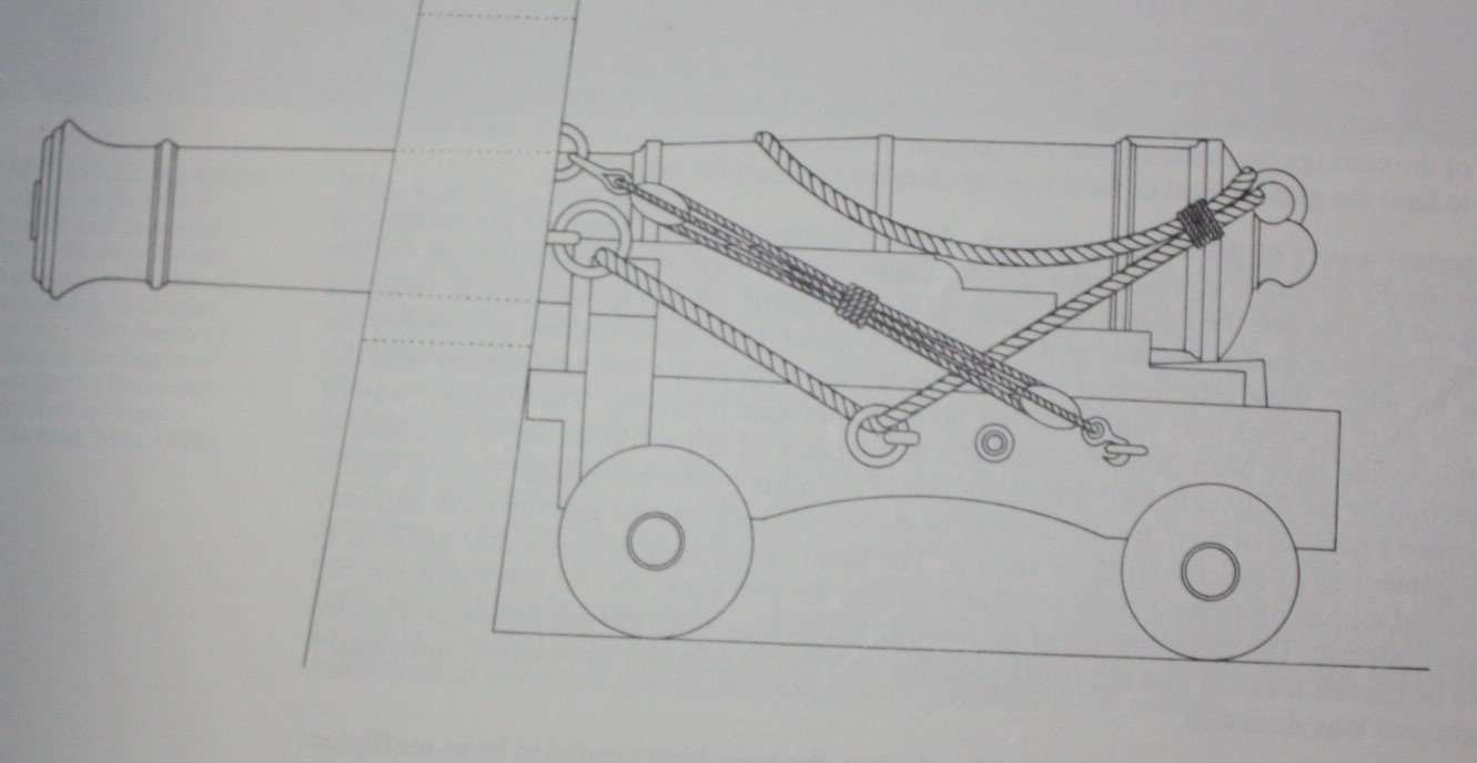
This is a REALLY nice action display Dafi. Questions for you, hope you don't mind. What are the two eyes on the inboard side of the carriages for? You have an eye for the training tackle (which would not be rigged once the guns were in action) but I was wondering about the extra two eyes. Also, the two breech lines seem to be unusual, but that may just be me. I cannot find any drawing, including on a 1795 carriage in Congreve's Treatise on the Mounting of Sea Service Ordinance, 1811 that shows two breech lines. The closest I found is a drawing based Congreve's drawing in Caruana's History of British Sea Ordinance that shows the breech rope folded over when run out but secured on page 382. (See below) Thanks in advance Allan
-
Hi Ian, I recall seeing something along these lines on a thread a few weeks ago here at MSW. Not sure it was ever resolved. Opinions regarding storing these pieces on the decks, cross beams and even on the channels were proposed. Allan
-
Bonjour Sandra, VERY interesting piece. Does it perhaps have a relation to Louis Renard who wrote the Atlas de la Navigation? A first addition of that book is available for all of our bibliophiles here at MSW. Little too pricey for me even though I have a translator here in the form of my admiral. There are later additions available for as "little" as US$2,000. Allan
-
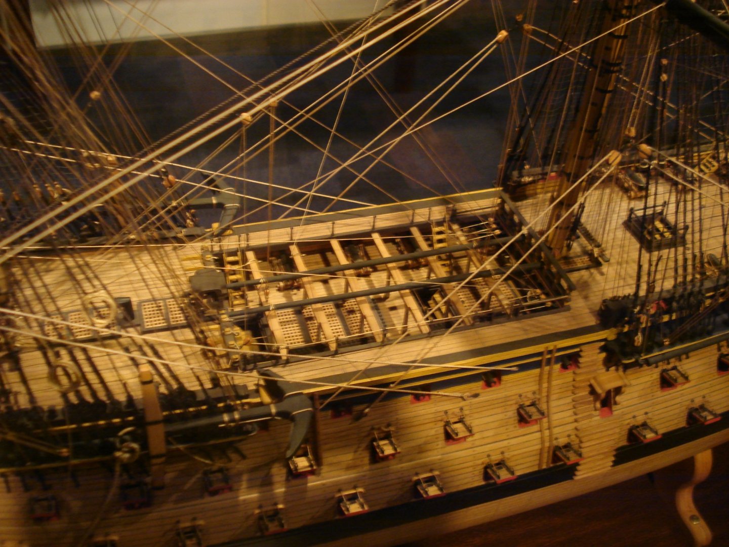
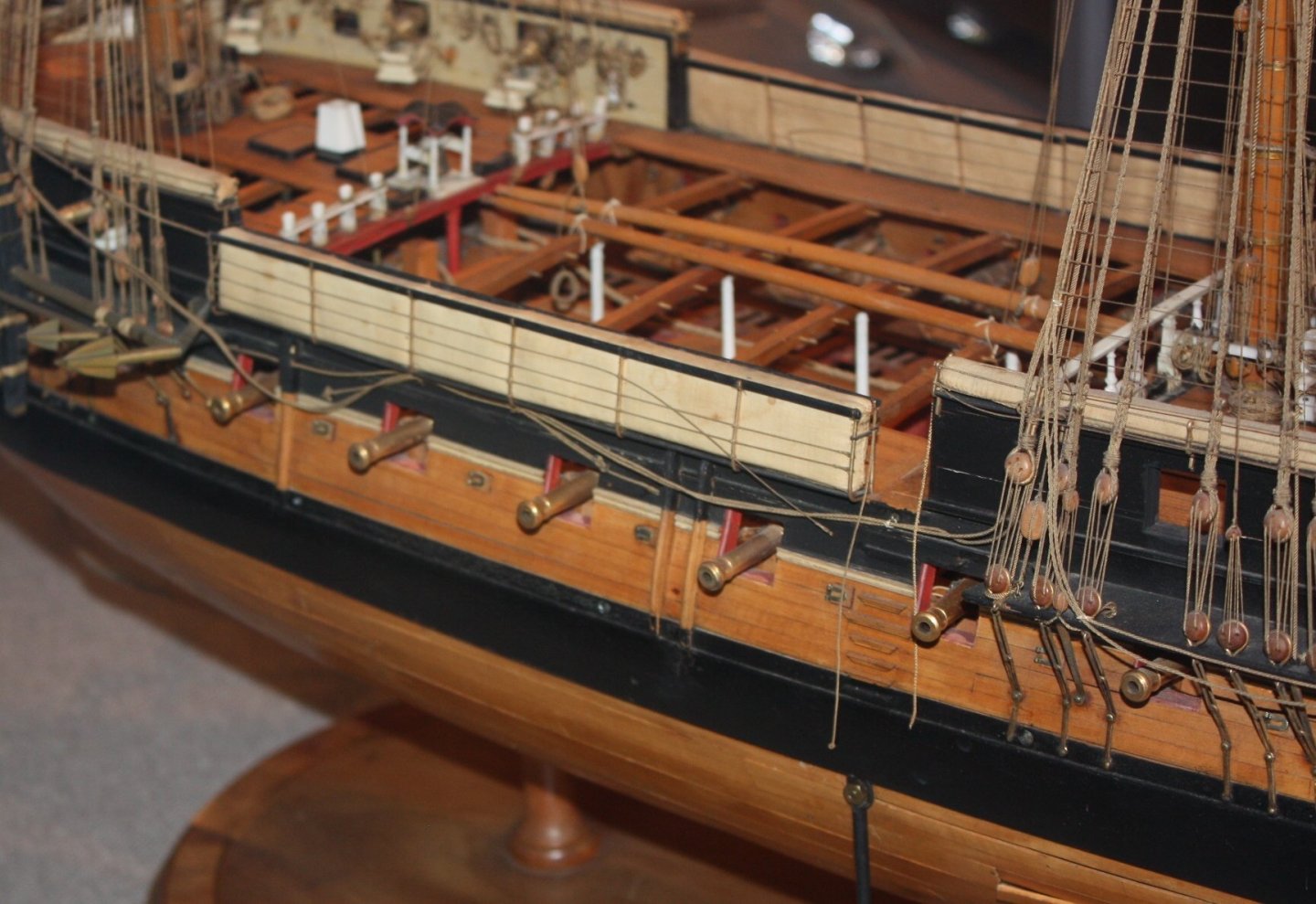
Ian Eugen is looking for information on stowing boats rather than spars which would likely have been laid on the cross beams along with the boats on a 74 of 1787. As to photographs or other contemporary information, if you find any, that would be an interesting subject to start. I found two photos of contemporary models in the Rogers collection at Preble Hall that follow. Not sure these are contemporary pieces or if they were added to the models at some later date. Allan
-
Eugen, Yes, that looks like how the US did it per the note from Roger above, but in the 18th century, some of the thwarts were fixed with knees so this nesting would not work. MAYBE one smaller boat could have been stowed upside down on top of a larger boat, but when there were three or more boats, this would not work. Nesting definitely would be a sensible solution IF the thwarts were removable, but they were not in the earlier years. Looking at paintings by Van de Velde, et al, I could not find any answers at all. Not one model in Anderson's Navy Board Ship Models has a ship's boat so no answers there either. Looking at photos of models at Preble Hall, same situation, no ship's boats on the models for which I have photos. Gallows would work for one boat but not two or more. Even with this, many of the contemporary models do not even show gallows on which a boat could be stowed so it did not interfere with the capstan. The more I research this, this more I wonder how this was done on the ships under 40 guns and all ships prior to about 1750 when there were not gangways and cross beams. Oh to have a Way Back machine for a few days........ Allan
-
Roger, Sounds like the US figured it out, albeit the next century😀. Eugen is specific about the RN in the 18th century and unfortunately the boats could not be nested as at least some thwarts were no removable. Eugen, Mays and Lavery go into theory on how the boats were stowed before the advent of cross beams on ships of 40 guns and larger about 1750 . They seem to agree that there is no contemporary information that they could find on how the boats were stowed prior to about 1750 on any size vessel or ships smaller than 40 guns even after 1750. Interference with the capstan operation, gun operation, and hatches are all taken into account in the theorizing. Stacking seems to be the consensus, but based only on it being a less troublesome method than any other. Perhaps Harland was using the term "nesting" loosely and really meant stacking. I did a bit more searching on the new RMG site with no success so far. Has anyone noticed the "Collections" system has had a major change? I am not sure I like the new system or old system better. The pictures on the new site seem to be as clear even though low resolution, and can be made larger than the old system without downloading so I am not sure if I like the old search system or new one better. (I find change in general annoying as I get older🙃) I really hope some solid contemporary information will be brought forward here. Allan
-
Greenstone Kudos to you for doing so much research on this subject but it is good to see all the copyrighted material originally posted has been removed. Based on the previously unedited post you have looked at Mays, Lavery and other sources and have come to the same conclusion as most of us. There seems to be is no clear contemporary information on stowage of ships boats when there is more than one, which would always have been the case on the actual ship in the 17th-19th century British sailing ships. One of the items you did post earlier showed and stated that the boats were nested. Can you tell us this source? As Lavery points out in The Arming and Fitting, that would be impossible as the boats always had at least some thwarts that were fixed in place and kneed so it would be impossible to nest them. I am once again in a situation where I could use some contemporary information on how to stow two or more boats on a deck of ships with fewer than 40 guns. FYI, the photo from the W.E. Mays book that you show in your edited post is no longer available on the RMG site from what I could find, but there are better photos, in color, of this same vessel on their site that might help. The ones on the website are the normal low res but there may be good information to be seen on the high resolution versions of these nine photos. https://www.rmg.co.uk/collections/objects/rmgc-object-66189 Thanks for bringing up this subject!! Allan
-
Brass Blackening questions
allanyed replied to stevenmh's topic in Metal Work, Soldering and Metal Fittings
Steven, Instead of glue, you might consider soldering the pieces together then filing away the excess solder, if there is any, back to bare metal which will allow the part to be blackened with no light spots. If you must glue, epoxy may work better for you as it easier to control and gives time to clean up excess before curing. Allan -
Hi Manic, Of special note from the above discussion Gregory referenced is the block selection. It is a common mistake on many kits that provide and instruct the use of a double block and single block for the running and training tackle on the guns.. Unless the guns were 32 pounders or larger there should be two single blocks, not a single and a double. I would not be surprised that there were exceptions for 24 pounders but as Enterprise 1799 was a schooner, she did not carry heavy guns and the rigging showing a single and double is not correct. As with many kits it is a good idea, and hopefully fun, to do some research as you move along on the build. Allan
- 89 replies
-
- 1
-
-
- Enterprise
- first build
- (and 2 more)
-
Thank you Kurt!!! The wooden tongs by our toaster may soon disappear from the kitchen if I forget to buy an extra one for the shop......😈
-
Kurt, When you say plain steel do you mean carbon steel or stainless steel? I would think SS is OK, but maybe you have found that is not the case. Thanks in advance. Allan
-
Hi CS Your question really is a good one but to which lines, ship(s), era are your referring? A little more detail might help get some helpful information. I know I would like to see this as this question was raised here at MSW not too long ago but no answer based on contemporary information ever came up. Allan
-
Hi Dave I found several crock pots (in the US) for under $US20. If it lasts 10 years like Kurt's, not a bad investment. It was funny that in doing the search for a mini crock pot, one of them had a picture of items often purchased together with that crock pot and these were wooden tongs and a bag of Sparex!! I found some at the following website in the UK but they are indeed more expensive ~~20-30 pounds. https://www.argos.co.uk/sd/small-slow-cooker/ Allan
-
Before I found Sparex 2 I used slightly hot white vinegar and salt (one cup vinegar to one tablespoon of salt) then after pickling, neutralize with baking soda dissolved in water. A crock pot works well, but if you go that route, get a small one and do NOT use it for cooking later. If I touch the part with my fingers afterwards I hit it with acetone. If I used clean tongs during every step between pickling and blackening , I never used acetone before blackening. Allan