allanyed
-
Posts
8,149 -
Joined
-
Last visited
Content Type
Profiles
Forums
Gallery
Events
Everything posted by allanyed
-
 Very nice display Ugo!! Was the idea of an elevating wedge from the kit? I had never before seen a British carronade with a wedge in place of an elevation screw. I checked all the carronade drawings in Caruana and Lavery's books and photos of contemporary models but none show a wedge, thus my question to you. Hope you don't mind. Thanks Ugo Allan
 -
Hello Cri-Cri Quick question, hope you don't mind. Were there actually slots for the deadeye chains cut into the channels on French ships in the 17th century? The British had holes rather than slots until 1771 according to Goodwin in The Construction and Fitting book on page 187. Also it may have been different for the French, I don't know, but for the British the outboard edge thickness of the channel was substantially thinner than the inboard edge. I am curious to know if the French and English differed on these two things. Thanks in advance. Allan
-
Jon, I would love to get back into a schooner model once my current project is complete, but right now I will probably go back to work on HMS Litchfield (1695) Then again, things change as they did with Ernestina and the Boothbay 65 projects thanks to you! If a schooner project does come up I would love to research some for which no models have been built previously. Allan
-
I agree with Vahur, they are all good for your purposes, but I have a preference for European boxwood (Buxus sempervirens) if it can be found, then a second choice would be Castelo (Calycophyllum multiflorum), which some people call South American boxwood. The latter is far easier to find, but you might get lucky to find some Buxus logs as I have seen a few ads in the past month or two. Allan
-
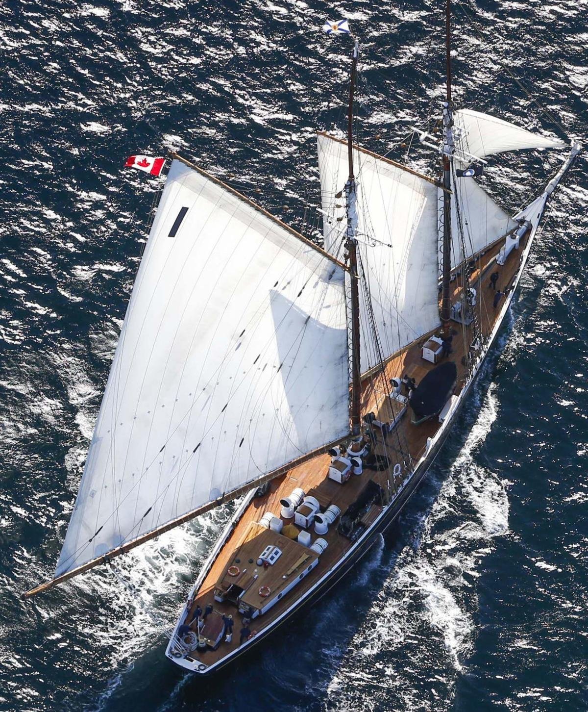
Toolman I believe these items were painted white on Bluenose II and Bluenose 1921, so the woods you mention are not really necessary except for the tops of the houses and entryways. If you want to have a light color though and no paint on the sides, good quality holly is a good choice. For the top of the houses I think any of these "wood" work. Look at photos of BNII for an idea of what they did, there are dozens of them to study. Not sure there are any color photos of BN1921. The below photo of BNII may help you. Note that the tops appear to be the same color as the deck planking, but I have no idea if it would be the same for BN1921. Allan

-
Greetings! Reporting aboard from Florida.
allanyed replied to Luord's topic in New member Introductions
Welcome from a SW Florida modeler! Hope you enjoy the ride!! Allan -
Were can I get this clamping device
allanyed replied to Cablejim's topic in Modeling tools and Workshop Equipment
DFXLII I REALLY like the clamps in the first photos. Regarding the last picture, if the planks are spiled or alternatively pre-bend the planks as demonstrated by Chuck Passaro, there is no need for any kind of pins or clamps when gluing a strake in place. Just a little finger pressure while the glue of your choice sets up. I find PVA will hold a properly spiled or pre-bent plank in less than a minute. Some members like to use CA and I am guessing that would hold in a few seconds. Do you bevel the edges of each strake to account for the radius of the hull? Thanks for sharing your clamp designs!!! Allan -
Were can I get this clamping device
allanyed replied to Cablejim's topic in Modeling tools and Workshop Equipment
Jim, Welcome to MSW. If you go to the forums section you will see a new member introduction section that you should try using to let everyone know a little about yourself. FYI, your post has no image of clamps. Allan -
HMS Bounty by Gct86 - Amati
allanyed replied to Gct86's topic in - Kit build logs for subjects built from 1751 - 1800
GCT86 Interesting screen name as it is the name of a color of a nail polish made by Odontorium. Regarding the thicknesses of 4mm and 5mm, maybe it has to do with the necessary tapering of the knee of the head both fore and aft as well as vertically. Your model scale is 1:60 so 4mm is about 9.5 inches full scale. The stem and knee of the head assembly, if it is 5mm, makes sense, as it tapers from top to bottom to match the keel and from the stem to the fore side of the knee of the head to about 6 inches (3mm at scale) There is actually a lot more to it but this taper is not always explained in kits even though it is an important feature. Allan -
Jon, I don't know which I am enjoying more, your build or the research that you did to get the photos and other information. Kudos Allan
-
Lacking additional information, if all Lunenberg schooners carried only 8 dories this seems to be the best information to go with. It is very nice to see research going into a project like this rather than accepting that a kit is always accurate.
-
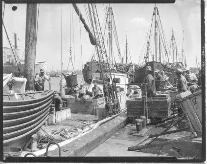
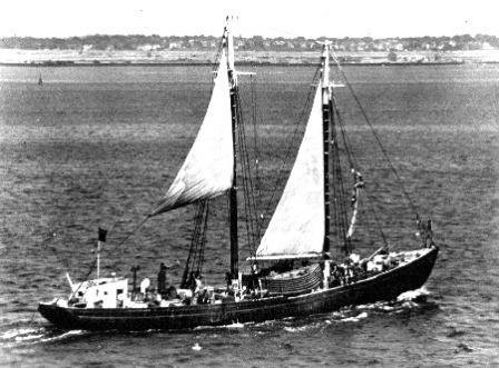
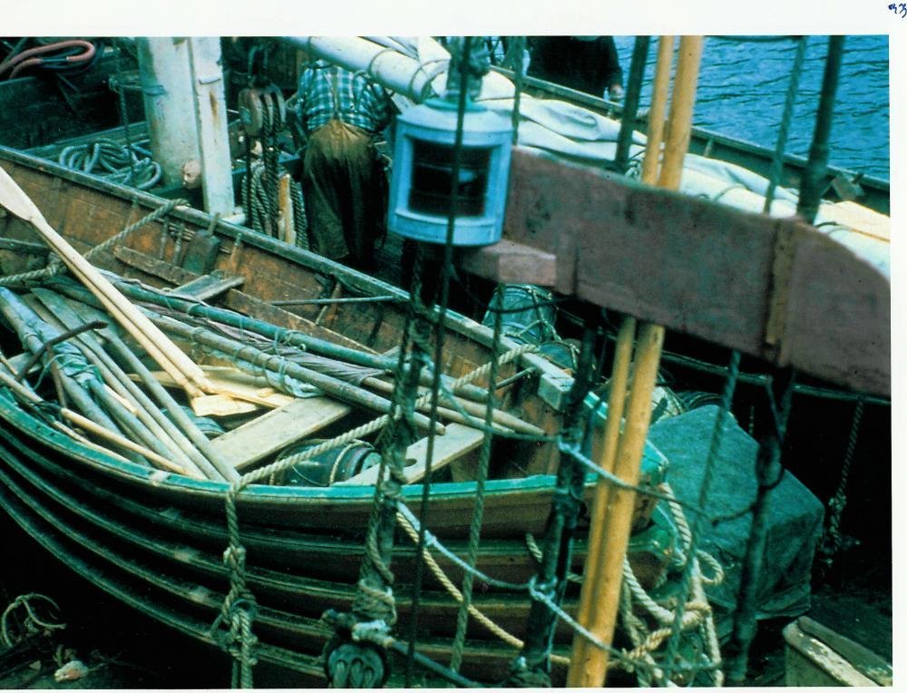
Good question Derek. I looked at some contemporary photos of fishing schooners of the early 20th century but many of the photos are grainy at best and difficult to see. None appear to have covers over the entire stack, but two that I found MAY have covers over the top most in the stack. A couple of photos that I found are below. There were more as well that popped up with a quick search on the internet. Assuming they were usually not covered I imagine they had drain holes with plugs like small boats of today. Are you speaking of the original Blue Nose? Looking at a bunch of contemporary photos of fishing schooners of her size, they seem to have at least 5 and usually 6 or 7 dories per side. I am curious if there were any rules or ratios of the size of a schooner and the number of dories, or perhaps it had to do with the size of the dory and type of fish they were targeting. Can you share your source regarding only 4 dories per side? Thanks! Cheers Allan
-
MONTAÑES by Amalio
allanyed replied to Amalio's topic in - Build logs for subjects built 1751 - 1800
Hi Amalio You mentioned you found the brick material in a previous post in Alamania (Germany?) Did it come already shaped as small bricks or did you make the bricks with some material that you got from them? I have made silicone molds then formed bricks made of plaster with some success, but would like to learn more on how you achieved such nice finished pieces. I suppose wood could work, but the texture you show is superior to wood even at our scales. Thanks Allan -
Dave, Goodwin shows a shallow groove cut into the hull in which the channels sit plus the various types of knees and standards and such that were employed over the years. I don't know if this groove was used in actual practice or not, but for the model I am sure there are a lot of methods used by members here that are successful. The following is just one that has worked for me over the years. if you just bolt and glue the channels to the hull then add the support brackets or standards, whichever is appropriate for the time of Endeavour, it should be plenty strong. I find it easiest to drill both the chain plate holes and the bolt holes in the channels before gluing them in place. Keep in mind that the slots with covering boards for the deadeye chain plates did not come into use until 1771 (Goodwin Construction and Fitting, p. 187) so, if he is correct, there were still just be holes through the channels for the dead eye chain plates in 1768. For the bolts that hold the channel to the hull, the bolt hole diameter should be such that it allows the bolts (brass rod works well) to fit easily but not be a sloppy fit. I then glue the channel in place. Once the glue is cured I drill with a slightly smaller bit through the predrilled bolt holes and into the hull so the bolts will fit snuggly when tapped home. A touch of epoxy is a good idea to be sure the bolts are actually holding the channel. Once you add the chain plates and deadeyes there will be even more strength. Hope to see pics of your work!! Allan
-
We have an unspoken agreement after 52 years of wedded bliss.... The bliss is because I say nothing when a QVC package arrives at the door and she says nothing when a package from Gilmer Woods, McMaster Carr, Syren, or other of my sources arrives. Even-Steven as far as we are both concerned. I no more understand why she buys some things any more than she understands the stuff I buy, EXCEPT we both know if it gives each us some kind of pleasure in its own way that is enough for us to know. (A pretty decent set of machinist squares can be found for $30 or less.) Allan
-
Why use just the plans from a kit rather than the contemporary plans for the actual details? There are contemporary drawings including two profile drawings and all her decks as re-fitted in Deptford in 1768 for her exploration voyage and possible additional changes in 1771 when James Gordon took command and Cook went to Resolution. I assume the kit plans and replica were based on some of these but which ones? The contemporary drawings are very high resolution and free, so probably better than anything in the kit or the replica. There are actually two contemporary profile drawings, one of which shows her original lines plus ticked lines showing the alterations to be made at Deptford. The other profile drawing is after the alterations. If you use the deck plans, be careful. There are deck plans from Deptford in 1768 showing her refit design, plus another from 1771 at Woolwich. i did not study them to find the differences so there may be some, or maybe not. They are all on the Wikimedia commons site. Go to the site and scroll down to the eighth page. All of the drawings can be downloaded in high res. https://commons.wikimedia.org/wiki/Category:Ship_plans_of_the_Royal_Museums_Greenwich Following these drawings will insure an accurate model based on original sources. Allan
-
Thukydides, Caruana is probably the best source and Lavery is also very good for information on guns based on contemporary information. Goodwin is a great source for many things, but sorry to say it is not of much help for rigging, including the guns. Allan
-
Gregory, No worries, if I had a dollar for every one of my own mistyped posts here at MSW I would have retired five years sooner!! Allan
-
David Have you looked at the six color photos of the model of the Earl of Pembroke (renamed Endeavor after its purchase)? https://www.rmg.co.uk/collections/objects/rmgc-object-66316 This is a modern (1947) model, but as it is at RMG I would guess there is some credibility to its construction (or maybe not???) Allan
-
Hi Gregory, I agree with you that Lavery is an accurate source, but I think you left out a couple words 😀 " A gun tackle consisted of a rope fixed to a single block, passed through a double block, back through the single block and through the double block again." Cheers Allan
-
48pdr cannon
allanyed replied to Thanasis's topic in Discussion for a Ship's Deck Furniture, Guns, boats and other Fittings
I second and third the above. The lower side view has the bore off center at the muzzle by 0.65" assuming the barrel is 9'6" long just for starters. This is probably not a good drawing to use for any model. It shows at the bottom that Trazzy Entertainment has a copyright 2011 on this drawing and they are indeed a game developer. Cheers Allan -
Doug, If you are like most of us, once you get a little sawdust in your blood you will forget plastic. You will also go through a lot of agita while learning, but it is so worth the efforts. You are very lucky to have over 40,000 teachers here at MSW to give you a hand so as suggested above, start a build log. Research your project as much as you can but if the research stalls, which it certainly can do at times, we are all here to help as much as possible. Dare I say GO Steelers or are you on the east side and an Eagles guy? I was raised in Western PA so the entire family, right down to the grandkids, bleed black and gold. Allan
-
Welcome aboard Doug. PA?? Pennsylvania??? Allan
-
Hi Vahur, Not really, but Eastern European, as all four of my grandparents came to the US from Ukraine, about 600 miles south of Estonia, between 1910 and 1914. I must admit, I used Google translator in my post above. My French and Italian are rudimentary but my Estonian is non-existent. Allan
-
Hi Marcus, Just my own personal take on this, but I would use the hardest and closest grained wood that I could find. It is easier to control the cut of the hard wood with SHARP chisels, sanding sticks, files and scalpel, taking little cuts at a time. Kevlar gloves?? Neat idea, but based on your experience since going to these, do the gloves cause more slips because you lose the feel of the wood when using a scalpel or chisel? Would love to hear more about this. Allan
- 17 replies
-
- 2
-

-
- windlass
- Dutch model
- (and 2 more)