allanyed
-
Posts
8,149 -
Joined
-
Last visited
Content Type
Profiles
Forums
Gallery
Events
Everything posted by allanyed
-

Doors
allanyed replied to Don Case's topic in Building, Framing, Planking and plating a ships hull and deck
Just remember the old joke, about no screen doors on a submarine. -
Doors
allanyed replied to Don Case's topic in Building, Framing, Planking and plating a ships hull and deck
Don, Many of the members do a TON of research on things like this before asking. I think it is easier at times to ask here, but honestly, there is sooooo much to be learned by researching as much as you can before hand and the answers could be pages long. As mentioned before, every time I go to my books looking for an answer to a question like yours I learn ten other things that will all come into play sometime in the future. I think you have the start of a good library, but consider Goodwin (Construction and Fitting of the English Man of War) and Lavery (Arming and Fitting of English Ships of War) if you don't already have them. There are others as well, but for me these have been extremely helpful. If you are going to get into rigging for the 18th century, seriously consider Lees as well. Everyone here loves to help all the other members when they can, but as Druxey pointed out, please don't expect a simple answer when there is none to be given because the question is so broad. Allan -
Doors
allanyed replied to Don Case's topic in Building, Framing, Planking and plating a ships hull and deck
Don, Which doors? Doors to cabins, through bulkheads at the QD and FC break, removeable bulkheads, beakhead bulkhead pantries, storage lockers, etc? Bulkheads and the set up of doors and even how they opened varied. When in the 18th century? There were many changes in 1757. Allan -
Brian, The anchor has more of a relation to the weight of the ship than anything else. Eagle was about 500 tons, so you can probably use the scantlings for anchors that Brian Lavery gives on page 33 of Arming and Fitting even though it is for British ships. The physics should be the same regardless of nationality assuming they have the same basic design at that time. He shows that the length of the shank for the largest anchor on a 625 ton vessel was 14 feet 2 inches, and for a vessel of 364 tons the shank was 12 feet 2 inches long. The length of the arms would be about 5 feet each and 4 feet each respectively. What scale is your model? You can do a simple ratio between 625 or 364 to 500 and use the lengths above to come up with the size anchor you need then scale it to your model scale. Maybe consider making your own if you want it to be the correct size. There are a number of drawings of anchors and anchor stocks on RMG Collections site that may also help as well as the detailed drawings and dimensions given by Lavery.
-
I know this is a bit off track, but we used to put snails that we would catch in the yard into a bucket of corn meal for two to three days to let them clean themselves up before cooking them. Can't see why it would not work for brass as well. 😄 Allan
-
THANK YOU PAUL!!! I have been very lucky to have a fellow member give me my first two lessons via Skype and I feel like I am making some progress. I will be practicing over the next few days before getting into more extrusions in our next session but my prof is a very patient man. I will definitely check out the tutorial by Lars. Thanks again! Allan
-
Permission to board from the Finger Lakes
allanyed replied to Freezing Parrot's topic in New member Introductions
A most warm welcome Mike. Yes, do please keep a log on your upcoming project. Before purchasing any kit, be sure to browse the build log sections here at MSW regarding kits. Some are excellent in detail and instructions including some designed by members at MSW who have actually built a lot of models so know what is needed. Others look glorious on the box cover, but when looking at the models themselves they leave a lot to be desired in actually using a good wood species for modeling, accurately scaled parts, rigging line quality and realism, easy follow instructions and more. Looking forward to seeing your work!! Allan -
Adding to the many wishes for a full and complete recovery. We will all miss your posts. Don't know about you, but with some down time available from making sawdust, I enjoy researching future potential projects as much as the actual build. Much harder to make mistakes when turning pages or looking through the 'net for contemporary information. Good luck Allan
-
Thanks Pat.
-
Mort, Looks like your gratings to scale which is very nice to see!! Not many are achieving this so kudos to you. Maybe I missed it, but how did you make the checker pattern? I usually draw it in CAD then print on paper and it works well. As an obvious fan of Victory, I hope you and your build followers have signed on to the Trafalgar TV series as shown in my signature below. It promises to be a big deal for all of us. Allan
- 60 replies
-
- 1
-

-
- victory
- caldercraft
- (and 1 more)
-
I am using a lot of Liquitex gold acrylic on the Charles Galley build and it is good. But, as with most glittery gold paints, it can be easily rubbed to a duller looking coat if handled too much before getting a protective top coat.
-
NAIAD 1797 by Bitao - 1:60
allanyed replied to Bitao's topic in - Build logs for subjects built 1751 - 1800
Very clean joinery Bitao. I really like the contrasting wood colors that show off your workmanship! Allan -
In addition to the fine color of the black pieces, the brass certainly looks like brass!!! Thank you very much for passing on the information. I have downloaded information and several sources. The code for the brass is MC 219. Have you tried their gold, MC 217? Thanks again. Allan
-
Thanks Pat, and yes please post the name if you can find it. I have my first lesson in Fusion 3D tomorrow with a fellow member here that is proficient in using it. We shall see if I am still a good student 😄 I agree Tim, based on the test pieces, resin is the way to go. Allan
-
Limber board holes
allanyed replied to Don Case's topic in Building, Framing, Planking and plating a ships hull and deck
Don, a lot of details on limber boards including the scantlings, direction of the grain being different in certain areas, sections to be left without the boards and the hole diameters can be found in TFFM Volume I. I understand that you are using scantlings for a sloop of war so would highly recommend this series of books for your build. There is too much to copy here without permission and the possibility of subsequent copyright issues. From a practical standpoint assume the boards are 3 feet long, 15 inches wide, 2.5 inches thick and made of oak. They would weigh about 35 pounds. How much can a sailor easily pick up with one finger in each hole, or two fingers, or three? From this you can figure an approximate hole size. This may sound silly, but I am sure practicality came into the design of many things on these vessels. Allan- 1 reply
-
- 4
-
-
The barrel is gorgeous Pat, as is the entire piece. Was the barrel made with black resin and/or painted or otherwise finished afterwards? i especially like the very subtle sheen from the light and you have answered a question I was going to ask the printer about getting the cascabel ring with no problems. Did you provide an STL drawing yourself? This is my problem as I have to learn how to do this and the old proverb found in John Heyward's book about teaching old dogs new tricks comes into play for me. Thanks for your post!! Allan
-
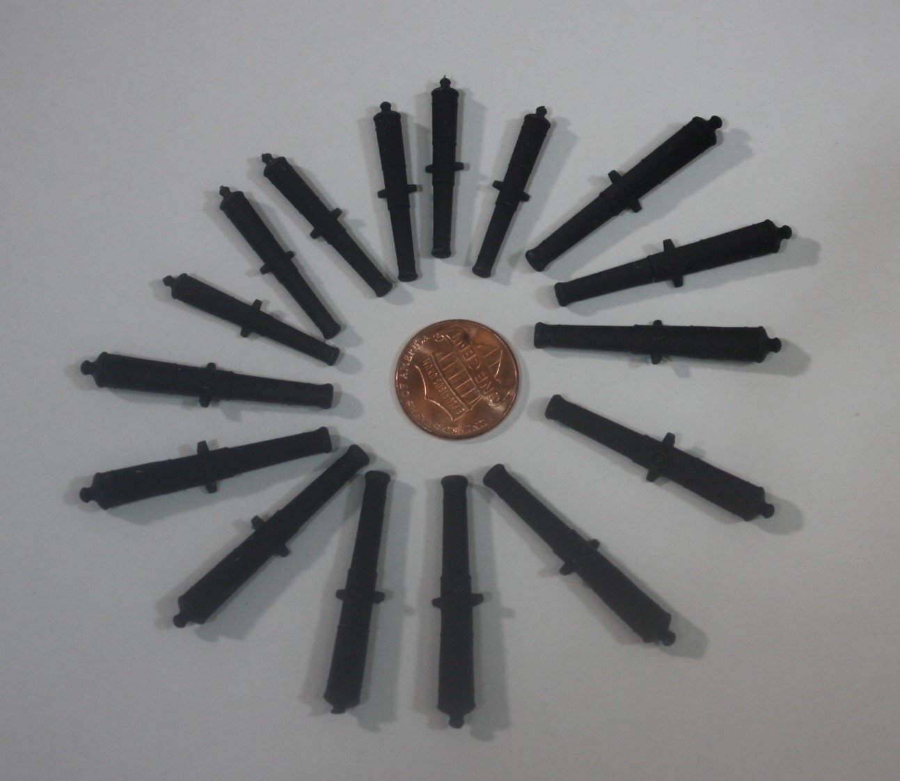
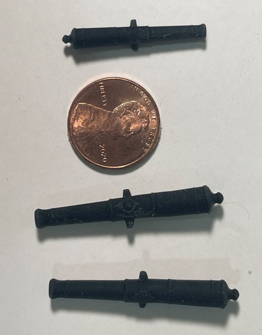
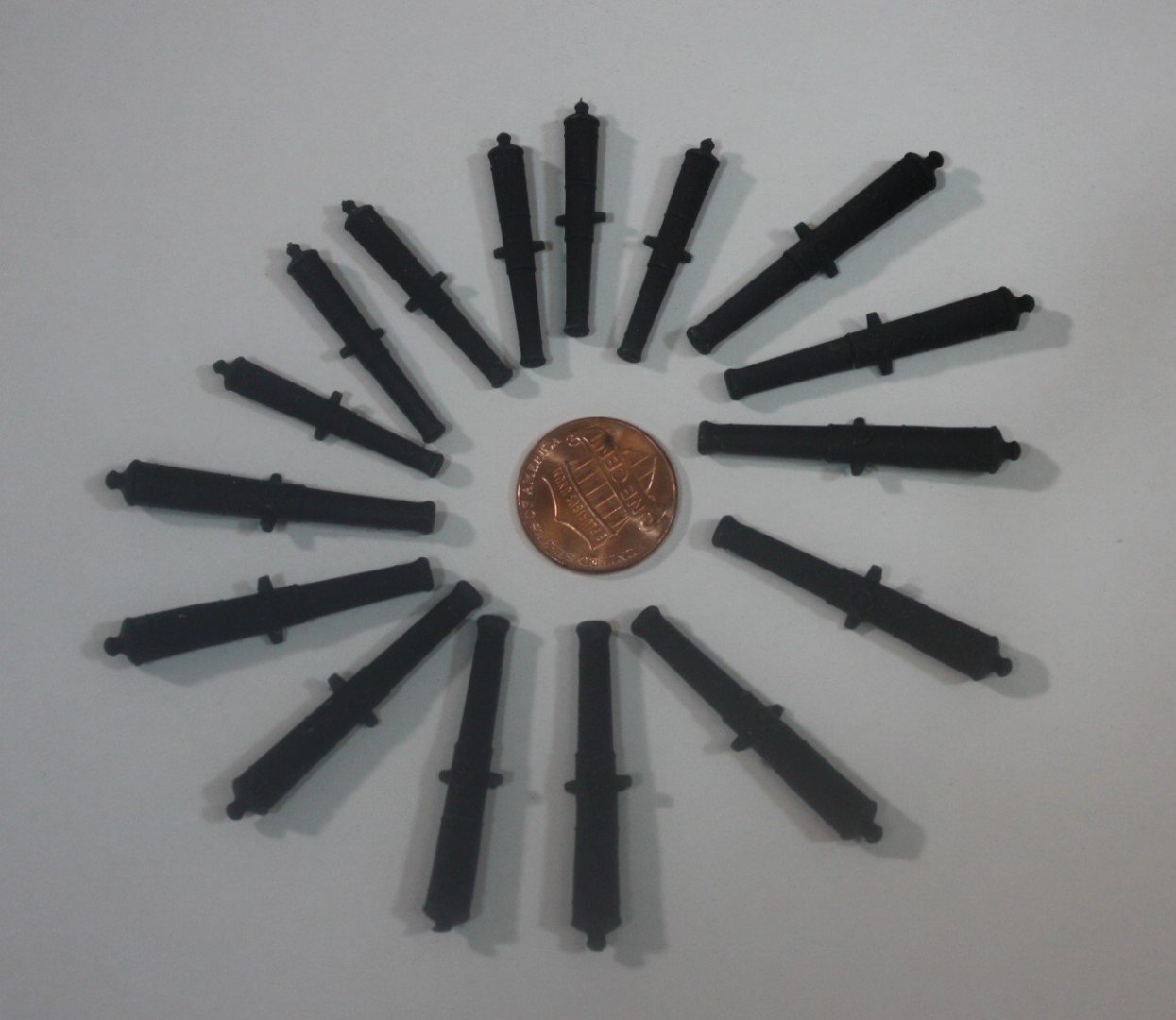
This is a repeat of my recent post in the Charles Galley build log, but thought it worth posting here as well. In working on the Charles Galley (1676) project I started working on the cannon barrels recently. As these are for 1676, I wanted to be sure the badge was correct with a rose and crown, the overall shape was appropriate for that time, including the number of rings, the shape of the cascabel, and the trunnions were tapered as they should be at that time, and well below the center line of the bore. There are no accurate commercially made cannon for this time period, and very few for other periods for that matter, so I made several of brass, made silicone molds and cast some with resin with pretty good results for the most part. I then thought about having them made with a 3D printer in black resin. I have no skills in 3D drawing and I am determined to learn how to do these drawings for future projects and items as well but for this project I was VERY LUCKY to get help from a fellow MSW member preparing STL format drawings. I sent these to a printer and asked to have some made in several materials including nylon, ABS, PETG and resin. The test was only $8 including postage so very reasonable. The resin performed much better than any of the other materials. He then made a dozen more of the 9 pounders that I needed and six of the 3 pounders. It is difficult to see the rose and crown badge in the photos, but I hope there is enough detail to see what can be done with3D printing. If anyone can recommend something like a Fusion 360 for Dummies or any book or tutorial or even another program in which STL drawings can be made without causing a lot of headaches, I would be grateful. If anyone is interested in contacting the printer that made these for me please feel free to email me. My email is in my profile. Allan
- 21 replies
-
- 14
-
-

-
Welcome to MSW Dr. K A 30 year old woman?? You are definitely one of our younger members coming into the fold. We need some young blood and glad you are here. Allan
-
Making some good progress and have given some names and email addresses of appropriate history professors to Adam to contact to alert their students of this project. Need more signatures from our members!!! It costs nothing but two minutes of your time to sign on board and help get the project in gear. Thanks Allan
-
But David, we all want to know why!!!! 😀 This is a little difference in over all length but at quarter scale could be in the neighborhood of 1/4" and bothersome. The main point though is that it is not up to the hounds as thought possible above. That would be a huge difference.
-
Platforms
allanyed replied to Don Case's topic in Building, Framing, Planking and plating a ships hull and deck
Glad to help Don, but for me hanging standards are more difficult. Hope that is not the case for you. The only problem for me with doing a thorough piece of research to get all the information is that I wind up seeing 10 other things along the way that I wind up reading. In the end though I suppose that is a good thing as I learn 10 things I did know about before the search on the original subject began. Good luck. -
I found rigging plans for a 24 gun 6th rate, 50 gun fourth rate, 80 gun 3rd rate, 90 gun 2nd rate and 100 gun first rate on the NMM site. All are from 1745. I inserted each into TurboCad and enlarged to full size using the scale on the bottom of each drawing. I then checked the height of the main masts on the drawings from the bottom of the mast inside the step to the top of the mast at the top of the cap, in other words, the entire length. Keep in mind the drawings were low resolution but when scaling to full size they are within a few inches or so of being correct. The following are the results. NMM ID number Type Height of mast on drawing Height of mast from Lees' multipliers and Establishment breadths for 1745 J8287 24 gun 6th rate 872 inches 875 inches J8283 50 gun 4th rate 1089 inches 1092 inches J8288 80 gun 3rd rate 1279 inches 1280 inches J8289 90 gun 2nd rate 1316 inches 1315 inches J8286 100 gun first rate 1380 inches 1370 inches I may be wrong to do so using such a small sampling, but I find that the lengths in Lees are based on the entire length of the mast. Hope this clarifies at least a little. This at least gives one an argument to back up the mast height based on the formulas in Lees for this time period of 1745 to 1773. Hopefully he was as accurate in the other time periods. Maybe someone can look for additional contemporary drawings in other time frames and confirm or refute the other multipliers he uses as well. Allan
-
Some folks advocate CA glue but epoxy is the way I would go. You might want to consider using miniature rope in place of what looks like string in your photos. I realize it probably from your kit supplies, but if it is not too late to change, miniature rope adds so much to the rigging of any model compared to common thread found in so many kits. I have no definite answer on this one, but were the seizings made with tarred line on untarred rope? Just curious. Allan
-
Platforms
allanyed replied to Don Case's topic in Building, Framing, Planking and plating a ships hull and deck
Hi Don, I believe Steel calls for hanging standards on the midship platform rather than hanging knees. This is not the case for the fore and aft platforms where lodging knees are used on each side of each beam or sometimes a combination of a lodging knee and a hanging standard. Cheers Allan -
Phil, I suppose the best thing we can do is hopefully find an appropriate contemporary rigging drawing for a specific ship or at least one that is of the same era and same rate as one's project. There are not nearly as many of these drawings as there are the typical deck, body, and profile plans that still exist. I just looked at Deane's Doctrine of Naval Architecture explanation of the length of the masts, and Lees' formula is of course identical for this time period. But, as you have pointed out, there is no mention of where the top is measured, at the hounds, the cap or somewhere else in either Lees' or Deane's books, at least that I could find. I am going to try to find enough rigging plans to make a reasonable study and download them to see if there is any consistency in where the measurements take place. Hopefully it will give all of us some base from which to work. Allan