


allanyed
-
Posts
8,149 -
Joined
-
Last visited
Content Type
Profiles
Forums
Gallery
Events
Everything posted by allanyed
-

HMS Discovery 1789 by Don Case - 1:48
allanyed replied to Don Case's topic in - Build logs for subjects built 1751 - 1800
Don, Your willingness to remove and redo should be an inspiration to others. Not just saying close enough can be tough, but kudos to you for not caving in! Allan -
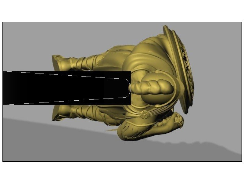
Lovely drawing Igor! I think the knee of the head is supposed to taper to about half the width, or less, than the width of the stem by the time it reaches the forward most point of the bobstay. (see white lines on the below picture. Again, your drawings are wonderful!! Allan
-
The National Archives in Kew. There are copies of contracts in a number of books as well, including Goodwin et al, but again, there is a cost involved. Unfortunately, not everything we need to use in our never ending research is free. Wish that was not the case, but.......... Allan
-
Fiberglass a boat Hull
allanyed replied to Riotvan88's topic in Building, Framing, Planking and plating a ships hull and deck
Riotvan, If you want to go the route of actual practice you could build a mold using your hull. I did this years ago making models of the Islander 36 sailing yacht and a couple Californian 48 motor yachts for their owners and they came out beautifully. I was lucky in that I worked for PPG Industries Coatings and Resin division at that time and had folks in the lab to show me the ropes. IF you want to give it a try, these are the basic steps as I remember them. After you are satisfied the original hull that you have has a perfect finish and is polished as much as possible, coat the hull with a mold release and rub and polish it until it gleams. Any soft rag will work for this. A rough finish is not desirable based on my own experience as it will show on the final product. Next paint on a couple layers of gelcoat onto your hull. Black is what I used, but any color should do. I used black to contrast with the final color of the hulls that I would be making. Once the gel coat is cured, apply the fiber glass and resin on top of the gel coat. I would not use woven glass as the weave can be noticeable no matter how many coats of your final finish that you use apply. I speak from experience on this. Unwoven fiberglass cloth is a far better choice and is generally thicker so will make a stronger mold. While the resin is still wet, you can add some stiffeners that will also allow the mold to stay upright when it is done. Glass over these pieces of wood stiffeners and let the entire set up cure. You will wind up with what looks like a small bath tub in the shape of your vessel hull. Once cured, remove your hull and you will have a finished mold from which you can make as many hulls as you want. When going to make the glass hull, apply and polish the same mold release onto the gelcoat inside the mold. Once it dries apply a coat of gel coat that is a contrasting color to the mold. In my case the hulls were blue or white. Once this coat of gel coat, which will be the extreme outside of your hull, is cured, apply nonwoven glass and resin in the mold. Once cured it can be popped right out and you have a glass hull similar to an actual fiberglass boat. You can add some wood battens here as well before the resin cures and lay some additional glass on top of these battens/stiffeners and they will be there forever and protected plus stiffen the hull. Sounds like a lot of work, but they were fun projects. I truly wish I still had those molds. Foolishly I got rid of them during one of our many moves. Such is life. I am sure there are tutorials on line so if you want to investigate further take a look as things may have gotten easier since I took this on back in the late '70s before getting into wooden ship model. Allan -
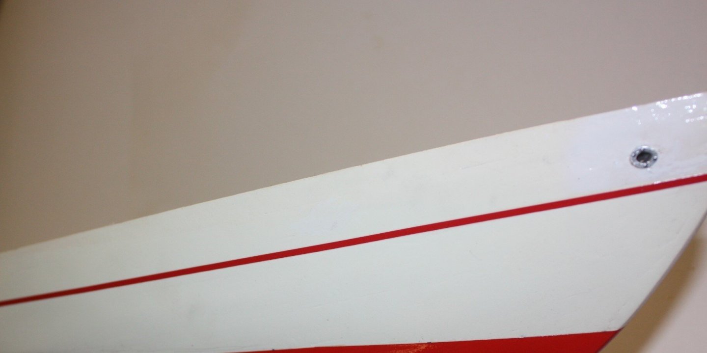
Bob, Thanks for the tip on fine line tape!!! I have always used painters masking tape but paint the edges with a clear varnish or poly to seal the edges before painting. This prevents any bleeding of the paint under the tape, but I will definitely give your suggestion a try in the very near future. Owl, Consider a pencil holding adjustable height gage as well. If you are looking to add just a stripe, not the bottom from the water line down, I have had great success for many years using pinstripe tape available on line or from auto supply stores. It adheres very well to a clean surface (cars are out there in all kinds of weather with this stuff staying put). When I apply the final four or five topcoats of a clear UV protective matte or eggshell finish to the hull, it further protects the pin striping from degrading or peeling off. The below photo shows a part of the water line that was set up with painter's masking tape and a pin stripe from the local auto supply store. Allan
-
Jonesy, For future consideration, look at scalpel blades and handle. The handles are not round so do not roll off the bench onto the floor or stick in your leg. They are sharper and available in packs of 100. Swann Morton is the brand I have been using since switching from Xacto for blades, but there are probably others. No need to get the sterile blades which tend to be more expensive. I still love Xacto for key hole saw blades and such. Allan
-
Good morning Don, Maybe ask Santa, Christmas is not too far away. Used copies of Goodwin can be had for $40 on Amazon these days. BTW, what is SOW? I am familiar with The Shipbuilder's Repository, Steel's Elements and Practice of Naval Architecture and Scantlings of the Royal Navy, but not SOW. Allan
-
Don, I double checked folio XL in the Sim Comfort book on Steel and for the platforms for a sloop of war the scantlings are indeed given for carlings that are four inches broad and ledges that are 3 inches broad. Keep in mind, Steel was 16 years after Discovery was launched, so may not be apropos. Then again lacking other contemporary information this is probably reasonable information to use. Check out contracts on similar sized vessels and they give dimensions of ledges and carlings as well. By the same token if you study a few contracts you will see that they do not conform to Steel in some cases. One example is the 16 gun sloop of war Echo, 1782. The following is an example of the description of a platform and lower deck from the contract of Echo: AFT PLATFORM ...................... beams sided 6½ inches and moulded 5½ to be kneed if directed, to be provided with Carlings and Ledges same as the Lower Deck................. LOWER DECK CARLINGS AND LEDGES ....................the Carlings to be 7 inches broad, and 6½ inches deep................................ The ledges to be of Oak 4 inches broad, and 3½ inches deep, to be spaced not more the 12 inches, nor less than 9 inches asunder. Do look at the ledges and breast riders in Goodwin's and Antscherl's books. Some look nothing like the majority of ledges which are rectangular in shape when seen from above and there are no places where any ledges lie in such a way that they would appear to be attached nearly side by side with the athwartships arms of the lodging knees. Hope this helps. Allan
-
Don, I double checked folio XL in the Sim Comfort edition of Steel and for the platforms for a sloop of war the scantlings are indeed given for carlings that are four inches broad and ledges that are 3 inches broad. Keep in mind, Steel was 16 years after Discovery was launched, so may not be apropos. Then again lacking other contemporary information this is probably reasonable information to use. Check out contracts on similar sized vessels and they give dimensions of ledges and carlings as well. By the same token if you study a few contracts you will see that they do not conform to Steel in some cases. One example is the 16 gun sloop of war Echo, 1782. The following is the description of the platforms and lower deck from the contract of Echo: PLATFORMS ...................... beams sided 6½ inches and moulded 5½ to be kneed if directed, to be provided with Carlings and Ledges same as the Lower Deck................. LOWER DECK CARLINGS AND LEDGES ....................the Carlings to be 7 inches broad, and 6½ inches deep................................ The ledges to be of Oak 4 inches broad, and 3½ inches deep, to be spaced not more the 12 inches, nor less than 9 inches asunder. Do look at the ledges and breast riders in Goodwin's and Antscherl's books. Some look nothing like the majority of ledges which are rectangular in shape when seen from above and there are no places where any ledges lie in such a way that they would appear to be nearly side by side with the athwartships arms of the lodging knees. Hope this helps. Allan
-
Don, I agree with Mark, the carlings look under sized when compared to the ledges. If you are using scantlings from Steel, the carlings would be 6 inches broad and the ledges 3.5 inches broad and no less than 9 nor more than 12 inches asunder (yes you are correct that this is the space between them, not C. to C.) For a lot of detail on how these go in pages 258 and 259 of TFFM volume I shows the solutions that you need. As well, Goodwin has an excellent drawing of this situation on page 72 in The Construction and Fitting of the English Man of War, including breast riders in place of ledges where necessary. Goodwin points out on page 74 that the while measurements of the ledges was stipulated (Establishments and contracts I presume) they sometimes varied according to their position. They are not always the same shape or breadth in the outboard tier. Allan
-
I bought mine on line. https://sigmfg.com/products/sig-silkspan-tissue The hobby shops near me had plastic type materials and no silk span, so maybe call ahead to your local hobby shop to avoid wasting a trip. It is pretty cheap stuff, but you will also need good quality artists tubed acrylic paints (not the cheap poor quality stuff in bottles found a few aisles over from the better quality paints), matte medium and some scrap wood to make a frame and plug that goes inside the frame. It is not at all complex, Follow the steps on the tutorials for the first try, then it is an easy go from there. There is some information here at MSW including in the scratch build of the Boothbay 65 as well as tutorials in David Antscherl's booklet and You Tube clips. Allan
-
The tutorials here at MSW by Chuck Passaro and David Antscherl give two great methods for preforming the planks and both work well. If the plank is either pre-bent with a form and heat or spiled, it can be held in place for about 30 or 45 seconds with finger pressure when using PVA and will hold. No clamps needed if the planks are properly shaped and bent ahead of time. Allan
-
For those who ever have doubts about silk span for sails, your model is a great testament to how well sails can be done, to scale, with that material, especially compared to the out-of-scale sails we usually see because they are made of cloth. It is a shame to see so many otherwise beautifully done models ruined when rigged with cloth sails. Allan
-
Yes you are! I think all of us get better if we keep trying new methods. I suggest you purchase David Antscherl's booklet ($8) on making sails from Sea Watch Books before Bob closes it down which will be sooner than later. For Victory, assuming smaller than 1:48, there is no way cloth sails and sewing them will look realistic as there is no cloth with a high enough TC or sewing methods that will be to scale. There is at least one well done You Tube video on making sails with silkspan, artist's tubed acrylics and matte medium with slight variations on the methods in the booklet mentioned above. Allan
-
Have you considered silk span for sails for future projects as the cloth scales and stitching are a impossible to make to scale? There are some excellent booklets and on line tutorials on doing this. Allan
-
The drawing on page 174 in Longridge shows tapered battens and he also uses word tapered in describing them. I have no idea if he was correct or if there were indeed variations from ship to ship as there are from source to source. Allan
-
Lovely work Will Tornados and even waterspouts are exciting to watch from afar. Seeing a big waterspout cross your bow, not so much fun, and I speak from experience. Allan
-
I really love this project. Very nice change to large scale yet manageable end result size wise. Allan
-
Your build is one of those that is worth watching from start to finish,,,,,, more than once. Allan
-
Sweet!!! Hope to see your next scratch in the near future. Allan
- 778 replies
-
- 1
-

-
- cheerful
- Syren Ship Model Company
- (and 1 more)
-
Stergios I had never thought about whether the horses and stirrups were tarred or untarred lines, and after a bit of research yours are absolutely correct for the time period for your model. No wonder that the seamen had blackened soles. Well done! Allan
- 1,144 replies
-
- 1
-
-
- snake
- caldercraft
- (and 1 more)
-
Patrick, Great joinery throughout! One thing to consider for the future, although fixable now if you want to do so, the wales taper in thickness at the bow to the same thickness as the surrounding planks so they do not stand proud of the adjacent planks where they fit to the rabbet. Thanks for all the photos and explanations on your build log. Allan
-
The anchor would be 3 inches long based on a twelve foot full scale, so 2 7/8 seems to be certainly reasonable if the anchor you wish to purchase is of the proper design for that era? Depends mostly on how accurate you want to be so it is totally up to you. In the end, in all likelihood, only you will know if it is a tiny bit short. Allan
-
Doors
allanyed replied to Don Case's topic in Building, Framing, Planking and plating a ships hull and deck
Don, Alas, frustration is part and parcel to model ship building at times, especially in scratch building. Even kits can be frustrating as has been so often seen in the build logs, but it is all part of the learning process. I have never built a kit but spent the equivalent amount of money of several big kits on books and even with my library built up over the years, I still get frustrated a few times each session at the bench. I am in the process of learning Fusion 360 and you cannot imagine the frustration I have gone through the past week or so, not to mention the frustration with me that a fellow member here has probably gone through trying to teach me the basics. It will come together. I had my first success with Fusion when a bulb went off in my head when I awoke this very morning and conquered the latest drawing task and the few minutes of satisfaction far outweighed the hours of frustration. You are some months into your project and have made huge progress, so keep at it! Allan -
Brian What scale are you working? Tx Allan

