allanyed
-
Posts
8,149 -
Joined
-
Last visited
Content Type
Profiles
Forums
Gallery
Events
Everything posted by allanyed
-

Platforms
allanyed replied to Don Case's topic in Building, Framing, Planking and plating a ships hull and deck
Hello Don David Antscherl's TFFM, Volume 1, pages 187 and 213 to 215 explains this in detail. Too much to copy here without violating copyrights. Suffice it to say there are no clamps, at least for the forward and aft platforms. Also, there would be a solid construction of lodging knees, not just the beams that rest on the ceiling. Allan -
In 1972 I was busy clearing the lot and laying blocks for the basement, laying bricks, and drywalling to name a few things. Only way we could afford a decent house at the time. Was a great learning experience, but never again. Unfortunately I burned every bit of the wood in bonfires and some in the fireplace over the next few years. Had I been into ship modeling, which came some 5 or 6 years later, I would have had a lifetime supply for everyone in MSW. Allan
-
I wish I had one of these back in '72. I cleared an acre of hawthorn trees with a hand held chain saw. They are thorny buggers and they had their revenge on me. Allan
-
For those who are interested in cutting their own lumber, the attached video shows a nice saw that might be of use. Click on the pic and the video should start. Allan DeathOfTheLumberJacks.mp4
-
You never fail to please us with your work. I always believed smaller can be just as satisfying and intriguing as big and fancy, and you have proven that very clearly in both cases over the years. Kudos Allan
- 433 replies
-
- 7
-

-
- open boat
- small boat
- (and 1 more)
-
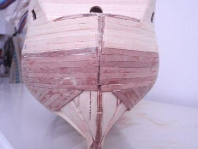
Harton Thank you very much for the clarification on the term stem post,,,,,,, live and learn 😀 As to the method you describe, if it works, why not use it? If one wants to become a better builder as you describe, do you think it would be better to learn proper construction techniques by following the methods the many excellent builders here use which are based on actual practice or go with the shortcuts and erroneous results from kit instructions? I looked at the post you gave and unfortunately the planking as shown in the photo above is not remotely close to how it was done on an actual ship as far as I I know, be it Spanish, English, French or Dutch. I may be wrong, and would welcome contemporary information if this kit style of planking was ever actually used in real life on these sailing men of war. Cheers Allan
-
Phil, Not sure I agree on this comment. For length of masts Lees does indicate if the formula to use for a given time period is based on length of the keel and beam and depth of the ship, length of the lower gun deck, or the beam on page183. These initial dimensions are readily available on many, if not most contemporary drawings with actual figures given or a scale on the drawing. He is specific about the length of the mizen being from the step in the hold and how to adjust if stepped on a deck above the hold. I may be wrong on this, but I believe it follows that the lengths for the fore and main masts are from the step as well. I have checked contemporary rigging drawings and these indicate that my assumption is correct. For one example, the contemporary rigging drawing of a 90 gun ship of 1745 from NMM has the main mast from the step to the top of the mast as 110 feet. The beam of 1741 proposals for a 90 gun is 48 feet. Using Lees' formula for this time period, 48X2.28 = 109.44 feet. Several third rate and 6th rates that I checked are similarly close. He does state that the dates he has chosen in the appendix are conjectural, but that they are based on various contemporary drawings, models and published contemporary works including those by Manwaring, the Admiralty list of 1640, Sutherland and et al. The forward by Alan Villiers and the Introduction by Lees gives a good amount of his CV and a list of his sources for various time periods. Cheers Allan
-
Thanks Hartron! I still have no idea how this can possibly work and have accuracy. Can you post photos of how this is done? You mention "stem post." Are you talking about the stern post aft or the stem at the bow? Probably your translator but I don't think there is such a thing as a stem post. Thanks again Allan
-
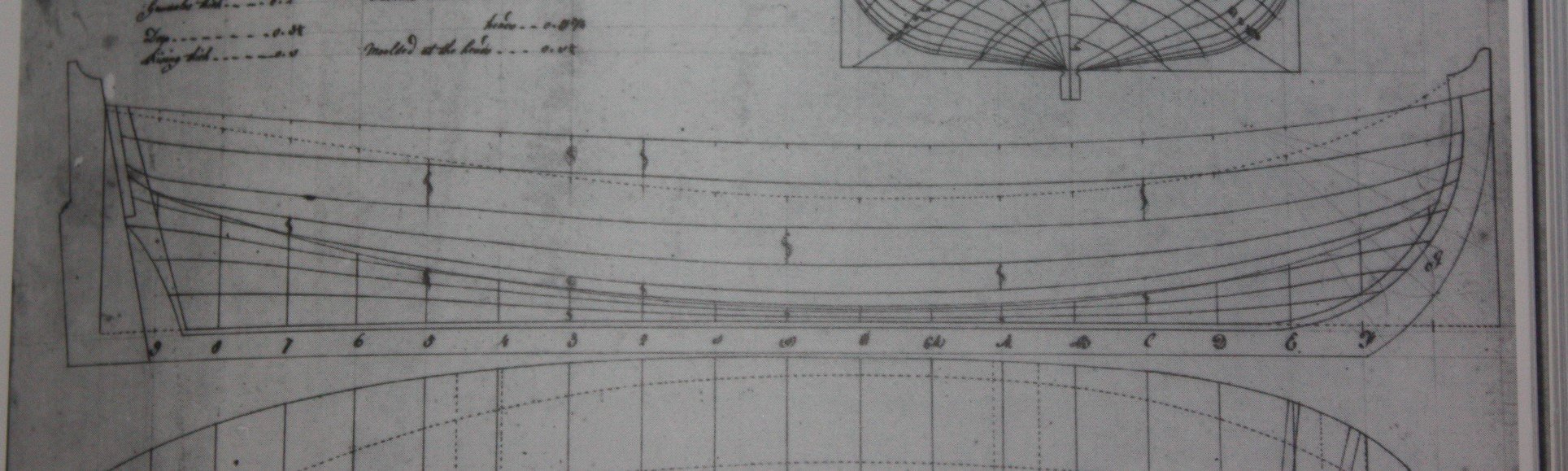
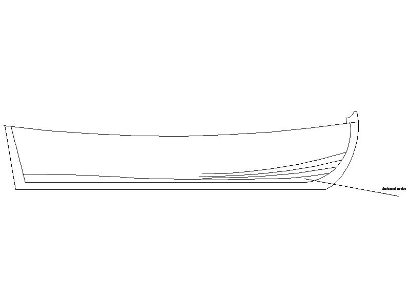
Hartron, Why would there be an opening in the strake for the stem, or sternpost for that matter? Karkka, The stake should lay against the rabbet. One needs to be careful not to take it too far up the stem, and giving it a Viking ship appearance like the lower plank in your last photo. The sketch below shows where the garboard lays. This is taken from a contemporary drawing at NMM so should be accurate. Allan
-
Karkka, I know this is a first build for you and you can expect some mistakes to happen. Hopefully the advice you receive from the members here will be taken in good spirit as it surely is given in good spirit. I hate to say it, but I would remove all of the planks and start over. If you used aliphatic glue, some water and/or alcohol will loosen up the glue. If you used cyanoacrylate, acetone should dissolve it. Then, before starting over, it would be good to thoroughly read the article you posted earlier. Pages 15-22 of the article explains about starting at the garboard plank and working up, but also shows how to mark out the strake lines on the frames and how they have to be tapered. It is not an easy thing to do and takes practice, but if you follow any of the planking tutorials here at MSW in detail, you will have success. Cheers Allan
-
I read Ken Follet's Pillars of the Earth series including the last one The Evening and the Morning which was a prequel to the series and covered Wessex, North Umbria, and Mercia so this period of time is intriguing to me. I did watch The Last Kingdom and enjoyed it thoroughly but will download Cornwell's books and give the books a try as well. I do appreciate and thank you for your guidance "Floki" Allan
-
Viking vessels never held an interest to me until lately, having become engrossed in the Viking TV series (in spite of the gratuitous battles.) Well done Floki (Gustaf Skarsgard) Allan
-
Papegojan 1627 by mati - FINISHED - 1/48
allanyed replied to mati's topic in - Build logs for subjects built 1501 - 1750
I really like that you are not adding sails. They are very hard to make to scale, even at 1:48, and in the end they will block the view of a lot of your beautiful rigging. Allan -
HMS Discovery 1789 by Don Case - 1:48
allanyed replied to Don Case's topic in - Build logs for subjects built 1751 - 1800
Looking good Don!!! Just remember to make sure the grating ledges run athwartships when you put them in place in the coamings. Allan -
Brett, what ship are you working on? A quick fix is do not use Mondfeld and get a copy of Lees' Masting and of Rigging English Ships of War1625 to 1860. In appendix 1 He begins with the length and breadth of the vessel. The initial formula varies a bit depending on the year the vessel was launched. The dates he uses are 1627 to 1669, 1670 to 1710, 1711-1718, 1719 to 1772, 1773 to 1793, 1794 to 1814, 1815 to 1835, 1836 to 1860. Once you have the length of the mast from the initial formula, it goes to mast, yards, sprits, and boom diameters, then lengths, then standing and running rigging. He ends with block sizes. There are 7 pages of formulas/ratios and is quite complete. As Mark points out above, a lower mast with a diameter of 24" has a lower stay that is 12" in circumference. There is also the same information here at MSW for free, and with one time period exception it is more accurate than Mondfeld. This is a spread sheet by Dan Vadas in the articles data base. Caution here though. While he used the formulas from Lees and made an easy to use spread sheet, his initial formula for the masts' lengths for the period 1670 to 1710 is completely wrong so everything that follows is wrong as well for this time period. Lees book would be the go to for this time period. If anyone has access to the original spread sheet done by Dan, it should not be too hard to fix this time period with the correct formula. For rigging details in general, Lees has been my go to for a long time as it is well written and has detailed drawings to go with the text. Allan
-
Sounds like you are trying to edge set a straight plank that has not been preshaped. The easiest fix for you may be to soak the plank then TEMPORARILY pin it to the frames and let it dry for a day, or hit it with a hair dryer to speed it along. The site you posted is nice but you might want to look at the planking tutorials here at MSW. Allan
-
Roter Löwe 1597 by Ondras71
allanyed replied to Ondras71's topic in - Build logs for subjects built 1501 - 1750
Those words on sculpture are attributed to Buonarotti - “The sculpture is already complete within the marble block, before I start my work. It is already there, I just have to chisel away the superfluous material.” Most know him more by his first name, Michelangelo. Allan -
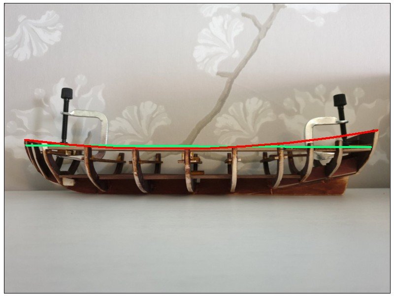
For a first time build, maybe it is better if you follow the manual even if it is wrong. At least you get some good practice and will learn some new things. The green line in the picture below is what you say the kit shows for the planking line. The red line is what it should look like. For the future, it would be good to study some books on how these boats and ships were actually built, then study the kits that are out there that are faithful to actual practice. I have no recent experience with kits, but from reading about them here at MSW, the best ones seem to be designed by Chuck Passaro, David Antscherl, and Chris Watton and his team. For a comparison of a ship's boat like yours, look at pictures of the boat kit designed by Chuck and you will see what it supposed to look like. One example of a build log that you may want to look at is https://modelshipworld.com/topic/22234-18th-century-pinnace-by-delf-finished-model-shipways-124-scale-small/?tab=comments#comment-663400 Of course if you have the tools, you can always take the plunge and build from scratch. Allan
-
Once the frame is cut out but not beveled, you can mark the bevel on the inside by measuring with a caliper from the paper plan and mark points along the inside of the frame every inch or so then draw a line to connect the dots. I try to stay just outside the line then finish up once the frames are fixed in place. Might be some easier way and I for one would love to hear about it! Allan
-
Hi Karkka With the angle of the photo it may difficult to see the curvature. If it is a straight line it is not right. For the time of the Bounty, at least, the planks don't lie on a horizontal line, same for the tops of the frames . The pics I posted are contemporary so can be trusted to be correct. Occre is not famous for accuracy in the design of their kits, but I think they do have the curvature based on your first photo. Cheers Allan
-
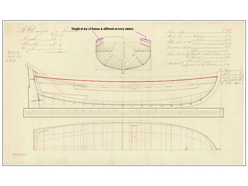
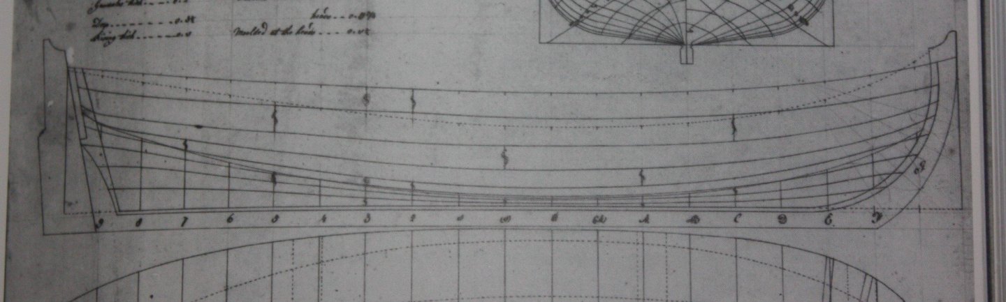
Karkka Can you tell us what kit this is? If I understand correctly, the heights of the frames are not the same height which is as it should be. They should be higher as you go forward and aft from the (0) station at the point of the widest breadth. The top planks should follow this curve, not be in a straight line like the red arrow you show in the first photo. Look at any body plan (one sample is below) and you will see that the stations vary in height. Subsequently the tops of the frames will follow this same line as the stations. Note that if the strips (planks) provided in the kit are the same width their entire length they will need to be shaped along their length if they are to lay correctly. Unfortunately most kits seem to forget this, which leads to planking on the model that is unlike anything that ever existed on a real ship or boat. From the photos you posted from the kit, it is pretty clear they show planking that is unrealistic. A contemporary drawing of a boat from NMM is below showing planking as was actually done so may be of some help to you. Allan
-
When I cut and paste the site in the post it comes right up on top and then just click on the arrow in the middle. Hope this helps.
-
Oh how I miss my basement shop with enough room to build at 1:24. Then again, the details had better be right, as are yours, otherwise mistakes would be glaringly apparent. Allan
-
BELLO!!!! Cutting the mortises for the gun port sills as you go and having them aligned perfectly is beyond what us mere mortals can achieve. For most of us it is best to raise the frames, then mark out and cut the ports. I am anxious to see if you decide to make them as you go and how these turn out and hopefully we can all say, "see, it CAN be done!" Ciao amico Allan
-
Pages 119-120 of Volume II in the TFFM 1767-1780 series by David Antscherl has a very good drawing showing a perspective of the great cabin looking aft and describes the internal upper counter planking and lockers in text and additional drawings. This would be applicable for any Swan class vessel, which includes Fly, 1776. In general, anyone building a model ship, especially a Swan Class ship would benefit greatly from having this series. Allan