


allanyed
-
Posts
8,149 -
Joined
-
Last visited
Content Type
Profiles
Forums
Gallery
Events
Everything posted by allanyed
-
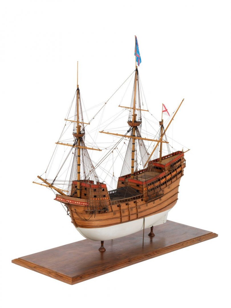
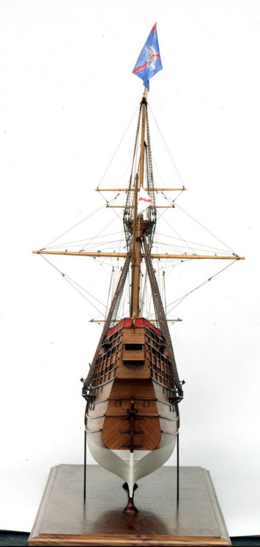
 For only your third ship, heck, even if this was your 10th, the hull planking looks quite nice! MAYBE the planking and wales should not rise at the bow as much as in the photo ala Viking ship style. I am not sure on this as I am not very familiar with planking techniques prior to the mid 17th century. If the wales are glued on top of the planking rather than being an actual strake of planking, this would not be terribly difficult to adjust if you wish. You can see the run of the wales on the model of Mary Rose at RMG. There are photos in several views. https://collections.rmg.co.uk/collections/objects/68966.html As this is a modern model, the interpretation may well be inaccurate to some degree, but hopefully, RMG gave some guidance to assure as much accuracy as possible based on the available information at the time. Not everyone thinks being as accurate as possible/practical is nit picking, so in the end, it should be what makes you happy and that the hobby is a joy, not a chore. Hope to see more pics as you make progress, thanks for sharing with us. Allan
- 50 replies
-
- 1
-

-
- mary rose
- caldercraft
- (and 1 more)
-
Hopefully this will be seen as a calming reply rather than a smart aleck comment which has no place here at MSW. This is more of a food for thought response, not a dyed in the wool absolute final answer. Yes there were sometimes lines secured in the tops. Yes they were secured to cleats or directly to the deadeyes in some cases. Yes, rigging varied over time periods, some shorter, some longer. Yes captains sometimes changed belay points to their own liking. The drawing from AOS shows what may be tiny cleats but I THINK more likely these are eyebolts. Based on Lees' formulas for dimensions of the tops and a beam of the RC at 24' 7", the top of the main mast should be athwartships 10' 9 1/2" or so. IF these were cleats, they would be only about 3.5" long so pretty much useless. IF they are eyebolts, to what purpose? Perhaps they were for lead blocks such as those on the sketches H30/1 and H30/2 at the deck but it does answer where the lines were belayed. I considered that maybe they were supposed to be the clevis pins for lead blocks that hang below the tops but the lines that are in question would not have lead blocks below the tops. Cheers everybody. Allan
-
Hi Azoun I checked with the few sources and found two detailed belaying point drawings and text descriptions, including one for 1742 which may be somewhat appropriate for Royal Caroline 1750. I cannot post these due to copyrights but they are in the book Masting and Rigging by Lees. None of the lines you name terminate in the tops in his description of the belaying points of every line. Looking at close ups of a number of photos of the tops of several contemporary models I could find only one line secured in the tops on one model, and it was secured to a topmast shroud deadeye. I could not tell what line this was though. This is not to say this is absolute for RC 1750. The Anatomy of the Ship series is terrific in many ways, but as with any modern source, specific items should be checked against contemporary sources whenever possible. For example, looking at the deck plans the cross pieces of the jeer bitts seem to be too long when checked against one of the contemporary drawings at RMG and there may not have been belaying pins in the cross pieces in 1750 as these came into more common use closer to the end of the century. There is no indication on the contemporary drawings that there were pin rails on the bulwarks on the RC. There were a total of six timberheads and no pins on the rail at the break of the forecastle on the contemporary drawing, but only four timberheads on the drawing you posted. Of course it is possible there were pins that were not shown on the contemporary drawings, but I THINK pins on this rail would be unusual before about 1785. Regarding the topgallant yard parrel, it was fitted the same way as the topsail yard parrel until about 1805. Unlike the lower yard parrels which had the lines leading to the deck, these had two eyes which were seized together on the foreside of the yard. From Lees' Masting and Rigging, page 84 The parrel ropes, after reeving through the ribs and trucks, were taken round abaft the mast and from there, one was taken over the top of the yard, the other below; they were then both taken round the yard and lead over the ribs in the grooves provided, round the yard by the ends with eyes spliced in, and so on until the ropes were used up; and the ropes frapped together. He makes no mention of the ropes leading to the tops or anywhere else. Again, this may not be appropriate in every case, including RC1750. RC drawing from 1749: https://collections.rmg.co.uk/collections/objects/459288.html Four high definition RC drawings after she was renamed Royal Charlotte in 1761 can be found on page 2 of the Wikicommons site https://commons.wikimedia.org/wiki/Category:Ship_plans_of_the_Royal_Museums_Greenwich There are differences in the contemporary deck drawings and the drawing you show from the AOS book. Note the hatches on the main deck and the stairs to the QD as examples. I would trust the contemporary sources before AOS, but Bellabarba and Osculati may have had other contemporary sources. Out of curiosity, does the AOS book reference any of these drawings or other contemporary sources? Just wondering if one or more of these drawings were used and if they were, why the AOS drawings did not necessarily follow them. Allan
-
Correct cordage sizes for stropping blocks
allanyed replied to glennb17's topic in Masting, rigging and sails
Welcome to MSW Glenn!!! What vessel, year, nationality? The short answer, according to Lees' Masting and Rigging, on page 164 the circumference of a rope strap on a common block is 1/4 the length of the block. Sorry to throw all of this other stuff out but you expressed a desire to show accurate detail. At your scale of 1:24, you may want more detail than just the circumference of the strop. A couple examples ...... some had single strops, some had double strops. Some of the strops were seized some were not not, it depends on where the block is located. Pin materials varied with block size. Blocks on pendants did not have strops, but rather the pendant had a long eye spliced in the end and the block seized in the eye with a racking seizing. Eyes on the ends of a strop varied in location, (the ends of stropping on blocks on spars had a short tail and a long tail for example). There are three pages of drawings and text in Lees' book, probably more information than you need or want, but know that it is available if you want to go all out. At 1:24 you have an opportunity to have blocks with actual sheaves, pins, &c. Allan -
Welcome to MSW Chris. Thank you very much for your service!! San Diego....... Navy, Coast Guard or Marines? I know the other branches are there but these were always predominant in that area when we lived in out there. Loved going out of H&M landing for albacore or fresh water fishing at Miramar and San Vincente reservoirs. Hope to see some of your upcoming work on a build log! Allan
-
Understanding Truss Pendants and other rigging things
allanyed replied to LucienL's topic in Masting, rigging and sails
Lucien, FWIW, according to David Lees in The Masting and Rigging, on page 67 chain pendants were not used until 1850. As Beagle was already de-masted and set in a marsh by 1845 and later renamed Watch Vessel Number 7 it may be the plans you have are not accurate. It would be a good idea to look for contemporary information to confirm information given with most any kit. The Anatomy of a Ship series is great, but again, it is wise to check contemporary sources or "modern" sources based on contemporary information before cutting wood or metal. It may be that Beagle was 30 years ahead of her time and had chain pendants when built but I would not think so. Hopefully if you do some research it will turn up accurate information. There are very detailed descriptions of both mast tackles and burton tackles in The Masting and Rigging on pages 42 and 66-67. Far too much to copy here without violating copyrights. In short though I believe the two are very similar with the mast tackle on the lower masts and the burton tackle on the topmasts but keep in mind that at least the burton tackle was rigged differently depending on if it was actually in use or not. Hopefully some member can give you more information. Allan -
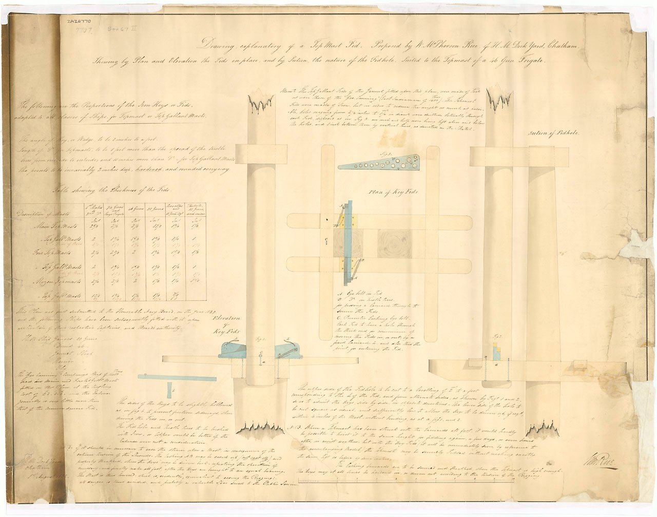
Grant, Contemporary drawing from 1839 below but might be appropriate for your year. I do not have a high resolution copy but you can buy this image in high res from RMG if you need something better than this resolution. The high res version will be easier to see the ratio of dimensions as well as the dimension table for various size ships' topmasts and topgallant masts.. Allan
-
I just noticed that Lees' sets of ratios that start with the lengths of main mast in the 17th century up to 1670 as 2.4 times the ship's beam. The Complete Modellist published in 1667, gives the length of the main mast as 2.5 times the length of the beam on page 2. While this appears to be a small difference, for a ship with a 30 foot beam this is a three foot difference. For a model of 1:48, this is a 3/4" difference, thus noticeable. The difference will then follow for all other masts, spars, and rigging. On the first page cover sheet it shows this copy is from of all places the Bibiloteca Nazionale Centrale di Firenze (Florence, Italy). This was first posted in the Nautical History section last year but some folks here may have missed it. https://books.google.com/books?id=_FCdAgS7HUoC&pg=PA2&dq=modeling+Thomas+miller+1667&hl=en&sa=X&ved=0CCcQ6AEwAWoVChMIqqzW1NS6yAIVRPJjCh2NRgXP#v=onepage&q=modeling Thomas miller 1667&f=false Anyone building a 17th century ship from before 1670 should find this work of help in scaling their rigging accurately. Allan
-
- 1
-
-
Thanks Lieste. The chart on that page is exactly what I was thinking about. Allan
-
Incredible workmanship that should be an inspiration to others, (including me!!!) Allan
-
Any ideas on what went into the various size barrels? Food, water, gunpowder, et al went into barrels, but was there any rule as to which size (or more than one size) was commonly used for given items? TIA Allan
-
Clever set up with the alligator clips!! I am thinking of pre-rigging frapped running out tackles which will then be hooked to the bulwark and carriage and this is a nice little set up I might try. Thanks for sharing. Allan
-
Hi Christian, If you do a search here at MSW on this Ships furniture forum you will find information that may be useful. One example is
-
when to rig the shrouds to the deadeyes.
allanyed replied to bobc622's topic in Masting, rigging and sails
Gregory, I have never heard of installing running rigging before the standing rigging but it does sound interesting. I understand setting up blocks and lines to the spars and such before setting the spars in place and securing the running lines but that would be about it. I can see how the standing rigging might be in the way at times, but the same would hold true, even more so, if the reverse is done and the standing rigging had to go around the running rigging. Govtech, You might want to consider investing in a good "how to" rigging book such as volume IV of The Fully Framed Model. Allan -
Mark, Found it, THANKS. Three decker,,,,, hmmmmm, not sure I want to tackle that kind of project at any scale. Then again....... Ah well, if I was 40 years younger with more time left than has gone by, maybe......
-
Welcome Bruce!!!! Before jumping into a build be sure to spend a few days or more researching here at MSW. You will get a good idea of what is involved with scratch building, kit building, or kit bashing. There are fantastic tutorials and articles on most every aspect of a build in the articles data base here. Due diligence is the key before spending your hard earned money. With 40,000 members there is what probably amounts to close to a million years of experience here at MSW to be shared with you if your own research is not getting you some of the answers you are seeking before jumping into a specific project. Allan
-
Welcome to MSW (I think) With a screen name like dodgy hack you have added another reason for me to fear Australia, what with the jumping , huntsman, and Sydney funnel web spiders, giant poisonous brown snakes, bull ants, dropbears, killer magpies, crocs, dingos, giant pink slugs, and the list goes on. (Yeah I know dropbears are SUPPOSEDLY a myth, but I wonder........) Hope to see you start a build log and I will be watching for any odd creatures hiding in the hull........ Allan
-
Chain Plates Gor 16th Century Spanish Galleons
allanyed replied to Bill Jackson's topic in Masting, rigging and sails
Have you watched the videos of the ten year San Salvador project? There may be some clues there as they did a ton of research before building the replica. I have no idea how accurate they have been but the old video here is quite interesting. There are lots of photos of this ship on the net since she was launched that show the chain plates which look like those of the 17th century. Also, there are photos of a 16th century galleon at the RMG Collections site. The model is modern (1988) but based on contemporary information. Note that one of the builders of the model was noted author James Lees. The description of the model is as follows: Scale: 1:96. A full hull model of a Spanish galleon (circa 1588). Built in the solid and plank on frame. Model is decked, equipped and fully rigged, including details such as a pair of anchors, deck gratings, flags, decoration around the stern and bulwarks, and a number of scale figures in the rigging and on deck. This model and the English equivalent (SLR0358) have been built from a design by David White, formerly of the NMM, based upon contemporary evidence and known naval architectural design. By comparison, the Spanish ships were much higher and rounded in the midship section. Spain did not possess a permanent force of sailing warships in the Atlantic before the 1570s. Twelve royal galleons built between 1568 and 1570 were deemed to small for fighting ships, and the three building programmes between 1578 and 1591 aimed to produce large ships that could carry a great deal of sail, many guns and would be able to overcome their opponents. This model represents one of the new, large galleons of the Armada period. You can get high resolution photos from RMG. Allan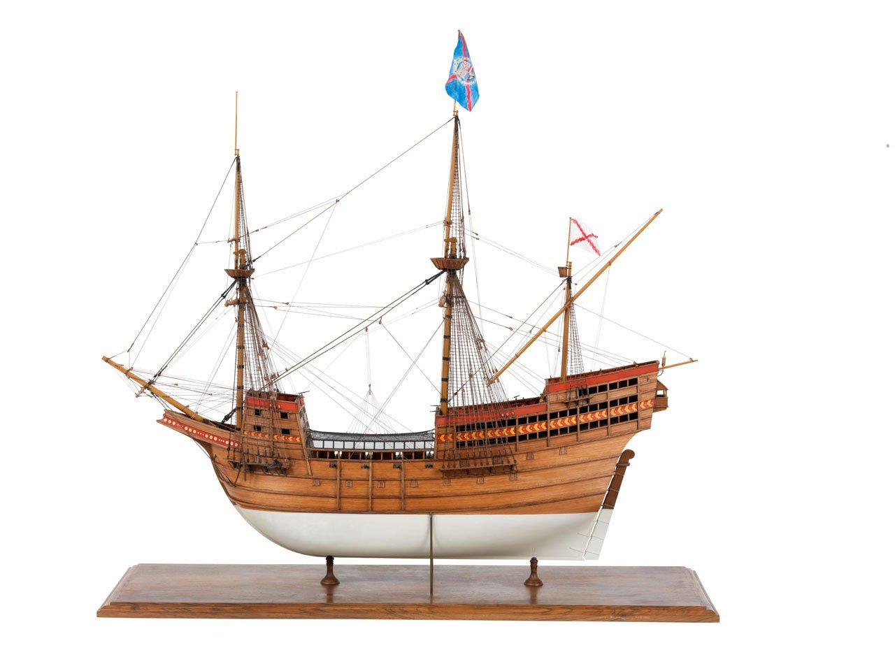
-
Bill, Your wish has come true with several kit makers. When you are ready for your next kit, look at the logs here at MSW and study the photos closely. You will be able to see the difference between the poor quality kits and the high quality kits. This includes quality of materials, scale of parts and instructions. Allan
-
There are contemporary deck plans, and there are contemporary deck plans. I spotted the incredibly detailed drawings of all decks of a 60 gun British ship circa 1745 in Caruana's volume II of English Sea Ordinance of all places where he credited RMG as the source. I went to the RMG collections and found the drawing there so it is available in low resolution for free, but I am thinking I may have to go for a high res copy for future use. It is not often that I have seen deck plans with such detail. While it is specific to a fourth rate and based on the 1745 Establishment, I am sure it will be at least partially useful in many respects for other vessels and eras including a good bit of the 1719 Establishment. https://collections.rmg.co.uk/collections/objects/81698.html Allan
-
- 3
-
-
Just ran across a deck drawing for a 1745 Establishment ship that is incredibly detailed, much more than most contemporary drawings in that it shows every ledge as well as carlings and beams and much more. It is for a 60 gun ship, but the information is likely applicable to other sizes in that era. Caruana showed it in Volume II of English Sa Ordinance and credited RMG. I went to the RMG collections and found the drawing there so it is available in low resolution for free, but I am thinking I may have to go for a high res copy for future use. https://collections.rmg.co.uk/collections/objects/81698.html Caruana notes that this may be the Weymouth on which Murray Mungo served as a carpenter. I saw that you are checking in here at MSW Don, so I hope you see this and that it helps you. Cheers Allan
-
Welcome. Do we call you Sascha or Wreck or just 1919? You will be very happy you came aboard as you now have tens of thousands of helpers!!! Allan
-
Dying/coloring rope; sources for purchase of quality rope
allanyed replied to Tomculb's topic in Masting, rigging and sails
Tony, Saw this stuff a few years ago and from what I remember it does not look anything like rope and the sizes are limited. There are dozens of sizes of rigging on a ship, but for a model usually 4 or 5 sizes of running and 3 or 4 sizes for standing rigging suffice, depending on the scale. You mention black. Keep in mind that Stockholm tar on ship rigging in the days of sail was more of a dark brown. I agree with the comment above, if at all possible get a color that you want, staining just adds another potential for a mistake. If you must stain, In addition to numerous stains and methods mentioned here at MSW there is also commercially available Stockholm pine tar which mixed with purified linseed oil makes a good stain that supposedly offers UV protection if you must stain your rope. Allan -
Bill, This drawing from Lees' Masting and Rigging, page 49 may also be of some help. Note that in a lot of kits many drawings, including the one you posted, look nothing like what would be found on a real ship. You can check realistic methods in a number of books and on some builds here at MSW so you're not relegated to using erroneous kit information. Allan
-
Will I searched for 30 minutes for the post you referenced about Thomas Gahms with no luck. I put in Thomas Gahms in the search box and nothing came up except your own posts. The search system is not always easy to use so sorry for asking but could you post the specific URL. No doubt my lack of computer skills is the issue, but would appreciate your help none-the-less. Tx Allan

