allanyed
-
Posts
8,149 -
Joined
-
Last visited
Content Type
Profiles
Forums
Gallery
Events
Everything posted by allanyed
-
 Johnny The thread count of the full sized material itself would be about 28 to 30 per inch full scale depending on the weight of the cloth. For a scale of 1:48, that would be about 1,400 per inch. I don't think there is any cloth that has an actual count that high which is why cloth sails never look right on scales smaller than 1:12. Also, the panels were about 2 feet wide, (1/2" at 1:48) with a 2" overlap so it is not possible to have sewn seams that look realistic at our most often used scales. The following shows details for various weights of doek (duck) cloth. Linen (flax) duck was the most likely sail material until cotton replaced it in the 19th century so the various charts should be apropos in most cases even though it was written in 1924. https://nvlpubs.nist.gov/nistpubs/nbstechnologic/nbstechnologicpaperT264.pdf TT, do give the use of nonwoven material like silk span a try on your next project. You will be pleased with how good they look compared cloth. When it comes to rigging, kits vary and there are sometimes errors such as the example we used concerning shoulder blocks in the wrong place even though, in your model, there would be no shoulder blocks on the lifts by the time Beagle was built. Braces never had shoulder blocks so maybe you can sand off the shoulder rather than re-rig the entire line with the correct style block 🙃 Allan
 -
Planking options
allanyed replied to Don Case's topic in Building, Framing, Planking and plating a ships hull and deck
Hi Don She was the HMS Squirrel, (24) 1785. RMG notes that the lines for this drawing are for the starboard side and were taken off in 1811, a year before she was broken up, so this was the planking as it actually existed. The port side should be the same. The drawing is signed by John Ancell, assistant to the Master Shipwright, Plymouth. As to why the "HMS" is not needed in the search box, perhaps someone at RMG can answer that for you. It never dawned on me to use the HMS when doing searches over the years so I guess I just lucked out. Allan -
Planking options
allanyed replied to Don Case's topic in Building, Framing, Planking and plating a ships hull and deck
https://collections.rmg.co.uk/collections Then click on Collections in the top bar of choices. Then type Squirrel in the search box and all her drawings come up. Scroll to box number 8 and the planking expansion should come up. Allan -
Treenail holes
allanyed replied to Don Case's topic in Building, Framing, Planking and plating a ships hull and deck
Totally agree Bob. I believe the ends were split and wedged thus more reason to caulk the ends. Allan -
Planking options
allanyed replied to Don Case's topic in Building, Framing, Planking and plating a ships hull and deck
Don, I think it would help if you study a planking expansion drawing such as for the Squirrel on the NMM site. The narrowest part should not be much smaller than half the widest part of the same strake on the inboard planking. For Squirrel the smallest is about 40% the width of the widest part of the strake. For the outboard strakes, the narrowest part is closer to 60% the width of the widest part of the same strake at its most narrow part at the forward end of the strakes. The expansion drawings show both inboard and outboard planking. Allan -
TechT Lots of things, but the first thing that looks odd is that there is a shoulder block coming off the yard arm with a pendant and the line appears to run aft. Shoulder blocks were used at the end of the yard arms for the lifts which ran inboard and up to a block at the cap then down, not aft and there was no pendant Actually shoulder blocks were not used after 1805 (Lees, page 69) I would strongly urge you to compare actual rigging practice with what the kits suggest as the kits are not always correct. Lees' Masting and Rigging is probably the best book (IMHO) to get as it covers 1625-1860 in great detail. There are others that are quite good, but if you were to only have one book and want to cover a wide range of years, this book is the go-to for many model builders for British ships of war. You might want to also consider getting some information on making sails that are to-scale. Sewn cloth sails are impossible to make to scale with sewing at scales smaller than about 1:12 or maybe 1:24. David Antscherl's booklet on making sails is a great source as are some very good videos on making model ship sales on You Tube The booklet is still available from Seawatch Books for $8. Hope this will be of some help to you on future projects. Allan
-
Treenail holes
allanyed replied to Don Case's topic in Building, Framing, Planking and plating a ships hull and deck
Bob Regarding caulking, the following is from the contract for HMS Echo (16), 1782 ......... All Treenails to be dry seasoned, clear of Sap, and converted from Timber of the growth of Sussex, or equal in Goodness, therefore, to be well mooted, not overhauled with an Axe in driving, and all to be caulked .......... The same wording is found in the contracts for Elephant (74) 1781, Curacoa 36, 1809 and Astraea 36, 1810. I could not find any reference to how "treenayles" were to be set up in any of the 17th century contracts I have in my files. Yep, another spelling of the same item I found in the contract for the HMS James Galley, 1686. Allan -
Welcome back to the fold Hank. Looking forward to a your build!!! Allan
-
Just a general question. The name appears to be a carved plaque. The English did not have any name on the stern except for a short period in the late 18ty century, and then they were painted, never carved. What was the norm for French vessels? Thanks Allan
-
Roter Löwe 1597 by Ondras71
allanyed replied to Ondras71's topic in - Build logs for subjects built 1501 - 1750
Ab, Your step by step carving photos are great. I love my micro chisels, but prefer to start with carving burrs as you show, then get the tiny details with the chisels. I FINALLY purchased a mill and have seen so much on your build where it can be used. Thanks for sharing. Allan -
Hope so Greg! Email me and let me know when you are down here and can meet for lunch. Allan
-
Glenn, your rope coils look terrific. You and others who have not seen this in the rigging forum here at MSW may find the following video of interest regarding coiling around a belaying pin. Allan
- 778 replies
-
- 4
-

-

-
- cheerful
- Syren Ship Model Company
- (and 1 more)
-
Glad to see her back at her home port!! Beautiful work as we have come to expect from both David and you. Kudos. Allan
-
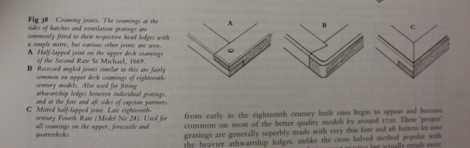
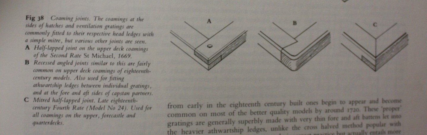
Gary, I just saw your digital level and think it is a great little device. Gonna get me one of those!! Regarding rounding the coaming/head ledge corners, I just learned it is best to do after the deck planks are in place around the the coamings. That way the bottom portion of the coamings remain square so the planking fits properly against the corners. A sharp chisel will put a little chamfer on the corner down to the top of the deck planks, then a touch with a sanding stick to round of the chamfer. Allan
-
Treenail holes
allanyed replied to Don Case's topic in Building, Framing, Planking and plating a ships hull and deck
Dz Doesn't a needle leave an indented ring in the wood? Neat idea none the less. Could also just drill the right size hole, smear a dab of PVA in a few holes at a time and sand so the saw dust fills the holes and the color will be close to that of the surrounding wood. Drill a few more, glue and sand a few thousand times. Allan -
Treenail holes
allanyed replied to Don Case's topic in Building, Framing, Planking and plating a ships hull and deck
What is the diameter of the tree nails (full scale)? What material do you plan to use? They should be very subtle if visible at all. You should not be able to see them from about 2 to 3 feet away. Look at the various build logs and will see a lot of cases of ships with hulls and decks that look like they have the measles because the treenails/trunnels/trennals were too large and/or too dark. Allan -
Welcome aboard, you have turned our world upside down! (and gave me a little headache😁) Allan
-
Thanks Mark, I will take a look at their website and print out the details and leave several copies in obtrusive places around the house, hint, hint, hint, hint for the admiral. David, I do note in your drawing and the photo from Mark that the corners are well rounded, something I see missing on a lot of models. Of course the rounding is pain in the neck as it is only above the deck line. Nothing easy in getting it done right 😀 Allan
-
There are a LOT of positive comments to be made on your build, but it is especially nice to see belaying pins that are at scale. This subject has been coming up a lot lately as oversized pins detract from otherwise fine models but yours are a very nice change. Allan
- 725 replies
-
- 1
-

-
- vanguard models
- speedy
- (and 1 more)
-
Rob, As a Nelson fan, if you have not already done so, please consider signing up for the Trafalgar TV series and Adam Preston's podcasts. Details on the series are in the Nautical/Naval history forum posted by Adam. Cheers Allan
-
Thank you Mark Very much appreciated. I really should put the Kriegstein collection on my birthday or Christmas list. Thanks for that tip as well!! Allan
-
Thanks David, I have always used the joint that you show and I actually learned it from your book, but it did not seem to be appropriate for the 17th century. Unfortunately I cannot get a close up that is clear of any contemporary models of the 17th century in my photos taken at Preble Hall to see what they used. I only bring this up now as I am about to start making coamings for the Charles Galley and want to be as accurate as possible. Thanks again Allan
-
I have never seen a ponce wheel that can space the nail pattern an inch or less apart at scale but would love to find one. The smallest I can find is 1/4 inch diameter with about 18 teeth so the spacing is twice what it should be at 1:48, and triple or quadruple at other popular scales. The photo Bob posted seems to have spacing similar to that of the Connie, about 1 inch or less so a 1/4 inch wheel would need about 40 teeth for 1:48 and 60 teeth for 1:64. For 1:96, 1:98, !:100 scales, it is much like trying to show treenails, impossible to make to scale. Maybe at these scales it is better to have no nail pattern at all. Allan
-
David, I cannot find anything with dovetails for the 17th century. The following is the half lap and other joints in Franklin's book and I was going to go with the simple half lap joint. TIA!!! Allan
-
Oh boy, dovetailing is going to be fun at 1:64. Heck, that would be difficult at 1:24!! Time to get out the 10X loupe.