


allanyed
-
Posts
8,149 -
Joined
-
Last visited
Content Type
Profiles
Forums
Gallery
Events
Everything posted by allanyed
-

boom rigging on a ship's launch boat
allanyed replied to Peanut6's topic in Masting, rigging and sails
Considering what Druxey wrote, the sailing rig was available but probably not used if for normal shore excursions where rowing probably was the standard means of propulsion so it is possible there were choices to be made depending on which was to be used. I wish George Wells and his machine were nearby. I'd tell him I was David Filby IV and ask to take a ride back in time instead of forward. At least going back I know which years in which to avoid stopping, starting with 2020. Maybe some member can build a new one like the one George used with success. I'd be happy to supply a five point seat belt to make it a little safer. -
boom rigging on a ship's launch boat
allanyed replied to Peanut6's topic in Masting, rigging and sails
Hi Spyglass, What you state makes perfect sense. As with so many instances on finding information on rigging I keep looking but cannot find much contemporary to Royal Navy ships' boats in the 17th century to the early 19th century. that describes cleats on the booms other than a cleat for the peek downhaul located under the boom. Steel has us following the description for schooners and sloops for launches and long boats, using hooks into eyebolts on the mast and taffrail for the downhauls and such. He also describes downhauls on cutters leading to the deck. Could you please steer me to a source on cleats on the booms as this search has been extremely frustrating. Many thanks for your help! Allan -
Hi Kev, Great catch! Horses were indeed in use on British ship's boats from the mid 18th century due to the problem with the sheets getting in the way of the tiller. It was put on the transom as you show. Remember that a double block had holes side by side unless they used long tackle blocks which had holes one above the other. Perhaps this is what was on the Bounty launch. I realize the kit calls the boat a jolly boat, but if this is supposed to be the boat on which Bligh sailed away, it would be a launch which was bigger than a jolly boat and constructed much differently. As mentioned in your other post Artesania Latina sells the same kit in different packaging and calls it the Captain boat for the Spanish ship San Juan Nupomuceno As suggested in your other post, if you go to the free download of Steel's Elements of Rigging and go to boat rigging chapter you will find a lot of contemporary details on rigging your boat although it is a bit confusing and as it sends you back and forth referencing one boat as a guide for others until you eventually get to what you want. Still it does have a lot of information you may be able to use now or on future projects. https://maritime.org/doc/steel/ Cheers Allan
- 129 replies
-
- 1
-

-
- Bounty Jolly Boat
- Artesania Latina
- (and 1 more)
-
George I am glad this subject came back to life as I learned something new today, thus it is a good day. In response to your question, as seems to be the case in so many instances, the type of wood for the decks depended on which era and which deck. Some decks had two different types of wood and even two different shapes of planks. The orlop and platforms were generally made with Deal rather than oak and often made into pallets with battens on their underside as they were not secured permanently to the beams. Rather, the pallets were held down with battens or rested in mortices that were as deep as the thickness of the planks, sort of overlapping (overloop from the Dutch) the beams, thus the name orlop, the slang abbreviation. (I never knew the origin of the word orlop until today🤪) In the late 18th century, gun decks sometimes were laid with top and butt or anchor stock planking for two or three outboard most strakes rather then parallel strakes. As oak became harder to find, elm was used on some gundecks as well. Elm was strong and had a great advantage of not splintering when hit with cannon shot, but rather broke into chunks. For the hull planks, whatever floats your boat as the saying goes. Oak on a ship does not work on a model as it shows grain so much it looks as odd as the walnut found in some kits. I prefer softer woods if it is going to be painted, otherwise hard woods are my personal favorites. In my experience I have not found that fruit woods such as apple or pear are any more difficult to work than castello or padauk, all of them being between about 1660 lbft and 1810 lbft on the Janka scale. Once the plank is cut to the proper shape I have been able to bend all of these with water and heat. Poplar and basswood are popular and much easier to work but the softness is troublesome for some people. I have seen a lot of models planked with yellow cedar in the past couple years that are absolutely gorgeous even though it is soft by comparison (580 lb ft). Allan
-
boom rigging on a ship's launch boat
allanyed replied to Peanut6's topic in Masting, rigging and sails
Kev, Looking at photos of models at the RMG Collections website, Mays' Boats of Men of War, and Lavery's Arming and Fitting, I could not find any contemporary rigged models or drawings showing a cleat on the boom. There may be more details in Steels Elements of Rigging which you can down load for free. It holds a wealth of information for the very late 18th century and into the 19th century. https://maritime.org/doc/steel/ Scroll down to the rigging section in the table of contents and then click on the appropriate page and there is information on rigging ship's boats starting at about page 220. I found it a bit confusing, but the jist was that there was mention of eyes and bands round the mast at the boom jaws for various lines, but no mention of cleats that I could find. There may have been cleats but I have never seen any contemporary information that indicates they were used, perhaps other members here have. Your first post asked about a launch, and then the next post mentions a jolly boat. Based on your signature you have a jolly boat from Bounty. Purely as a point of information the boat on which Bligh was put was a launch, probably about 23 feet long. The term jolly boat in the late 18th century was sometimes interchangeable with small cutters of 16 feet to 18 feet. Artesania makes the same kit with different packaging and markets it as a boat for the Spanish ship Nepomuceno which I found to be rather strange. See side by side photos of the both kits pictures below. Allan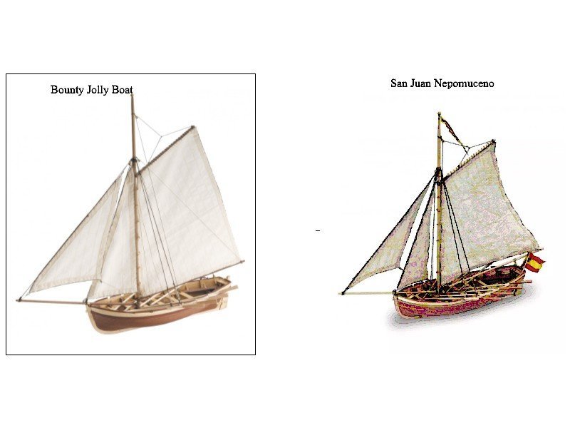
-
Welcome to MSW Eurus (AKA Greek god of the east winds -- I had to look it up😃) Your opening struck a nerve. I too wanted to be a naval aviator but it was not to be so I headed to sea as a merchant marine engineer and so my romance with the sea began. I love that you started with something manageable for a first go at ship modeling. As you move forward, if you are going to forego scratch building and go with kits please read everything here at MSW on the many kits that are out there. There are quite a few that are top quality and yield beautiful and historically accurate results. There are also some that create a ton of agita for the builders because of poor instructions, poor quality materials and many with out-of-scale and/or inaccurate parts, and so forth. Also be sure to read the forum here on piracy. There is a list of kit pirate manufacturers to avoid and build logs on kits by these manufacturers are not permitted here. Know that you have a huge library of previous posts at MSW from which to learn as well as more teachers/helpers than you probably want. Cheers, Allan
-
Any rules of thumb or tables for sizing hearts?
allanyed replied to Tim Holt's topic in Masting, rigging and sails
Tim, No apologies necessary, we are all short of knowledge in this hobby of ours, just depends on the specific subject that we are encountering. I just did some more searching and found the following information that might be of more help. From Lees' ................. As before, the heart is 1.45 X the circumference of the stay. The diameter (width?) is .075 X the length at the widest point and the thickness is twice the DIAMETER of the stay. The inside opening where the lanyard lies is 0.33 the widest dimension of the width and the smallest part of the opening was 0.25 the widest dimension of the width. I cannot find anything regarding the circumference of the lanyard, but assuming five passes, it would be the widest portion of the inside opening divided by five. Unfortunately there does not seem to be anything straight forward so most of us are without total knowledge (I hate to say ignorant 😄) As Mark suggests, once you have the sizes you need, confirm with the supplier the dimensions, at least the length and width outside. Allan -
when to rig the shrouds to the deadeyes.
allanyed replied to bobc622's topic in Masting, rigging and sails
Bob, As the shrouds are in pairs except for a swifter when there are an odd number of shrouds I cannot see how anyone can get the two upper deadeyes in any given pair at the right position if done off the model. Even the swifters, which would have a splice so there is one swifter port and one starboard, would be problematic. If you do a search here at MSW on setting up shrouds there are a lot of posts on how others have gone about setting up the shrouds with success. Allan -
Planking the ship boat
allanyed replied to Senza Timone's topic in Modeling tools and Workshop Equipment
You have joined the club Without Helm. We ALL have gone through this, and even after MANY years we are all still in the learning mode ( I know I am) Allan -
Any rules of thumb or tables for sizing hearts?
allanyed replied to Tim Holt's topic in Masting, rigging and sails
Hi Tim, Forgive me but I am not sure I understand your question. If you have the circumference of the stay or collar (from Lees or Vadas or contemporary sources tables) you can size the heart. Once you figure the size, check that against the hearts you find to see if they are the right size. Example HMS Bristol, a 4th rate ship launched in 1775 Length of the ship on the gun deck: 148 feet Breadth: 40 feet 7 inches For 1775, only the breadth was used in the initial calculation for the length of the masts. Length of the main mast - 2.23 X 40.583 =90' 6" Diameter of the main mast - 0.9" per three feet of length -- 0.9X30.2 = 27.18" Lower stay circumference- 0.5 X 27.18= 13.59" (diameter 4.32") The heart would be 1.45X 13.59= 19.7" long (and about the same width at the widest point.) 1:48 scale 19.7"/48= 0.41 inches long If your ship had preventer stays, a quick calculation is that they would be 0.7 X the size of the stays so the hearts would be proportionately smaller as well. Based on the scale of your model and having figured out the proper stays' circumferences at scale size, you will be able to check if the hearts that you are looking at are the right size for any give stay. I doubt that kit or after sales suppliers are able to offer enough sizes to help everyone what with various years, rates, scales, &c. but they may be close. If they do not have the various sizes that you need, you might consider making your own. I hope someone checks these numbers in case I missed something 🤪 I hope this was of some help to you Allan -
Planking the ship boat
allanyed replied to Senza Timone's topic in Modeling tools and Workshop Equipment
Without Helm, Hope you don't mind a little constructive information as building these little guys can be harder than the full size hull at times. If you would like the scantlings for everything on the boat, please feel free to PM me. Just need to know the length and type of boat for which the scantlings would be. There are "how to" posts on planking small boats like yours here at MSW. I notice that you seem to have run out of room at the bow because the planks are not tapered as they move forward so maybe consider taking a look at Druxey's recent build log (click on the image below) for some great tips on making a ship's boat. I think you will find this to be extremely helpful in making a boat that looks great. Allan -
Christian, regarding your July 4 post on cannon you said you would go with "normal" guns. Do you mean guns from the kit? If you want to have cannon that actually look like cannon of that era for French vessels, you can have them made by a 3D printer at a reasonable price. I provided a drawing of two cannon sizes in STL format (I had someone help me as I had NO experience with this kind of drawing) to a small printer company and he made me 20 cannon for $8 total, including postage. I bet there are some folks that could help you locally with the drawings if you do not know how to do this yourself and there a lot of local small printer folks that could probably make them for you in black resin (which was the best after we tested several materials) for a very low price. Even at a very small scale it is easy to include the cipher and tapered trunnions and other tiny details and they will all show up on the finished barrels. J'espere que ca aide!! Alain
-
From what I can see in the photos you have the tiles such that the holes are pushed in as if nailed to the hull which is as it should be. It is a very very nice change to see this done correctly rather than have bumps stick out as if they were bolted to the hull. Well done. Allan
-
Soaking plank
allanyed replied to zamboknee's topic in Building, Framing, Planking and plating a ships hull and deck
Zambok, What kind of wood and how thick is it? A lot depends on the type of wood (ebony can soak for a year and not be pliable) as well as the thickness. I have soaked holly that is 1/16" thick for five minutes and it could be bent around a carved plug for frames for a ships boat without heat. Castello boxwood thicker than about 1/4" is difficult to bend even if soaked long enough for the water to fully penetrate. But, while gently bending and hitting it with a hot air gun (don't use her hair dryer unless she is out of the house for a while) it can be bent around a form while wet with some ease then clamped in place until it dries completely via the hot air, or air dry for some hours. Thinner stock pf this wood is not so bad. The amount of grain and direction will also contribute to the ease or difficulty. Dry bending with heat is another option that few people use but can be tried as well to see if it works for you with the wood you are using. Allan -
What Glue is Best for Rigging Ropes?
allanyed replied to Bill Jackson's topic in Masting, rigging and sails
Regarding CA on rigging, ditto on the above, don't use it. CA is helpful and for some it is preferable in some instances of a build other than rigging, but it is not a necessity anywhere. White PVA diluted as discussed above is the ticket! -
HMS Discovery 1789 by Don Case - 1:48
allanyed replied to Don Case's topic in - Build logs for subjects built 1751 - 1800
The fact that you are not settling for the "no one will ever know" route is a great. Good for you for taking the time and making the effort!! Allan -
Any rules of thumb or tables for sizing hearts?
allanyed replied to Tim Holt's topic in Masting, rigging and sails
Tim, I know it sounds complex, and in fact it is for most of us. (Caveat, if you are talking about the whaler Swift that the Royal Navy purchased in 1804, some things may not apply) The size of a heart, as are all masts, spars, ropes and blocks, is related to the size of the ship and year. If you take the Vadas spread sheet and enter the extreme beam and length of the lower deck in the appropriate year segments in the spreadsheet, you will get the size of the masts, spars and ropes. From the size of the rope you can then calculate the length of the heart, which, according to James Lees, is 1.45 times the circumference of the stay for which it is intended. Each stay and collar is a different circumference so each heart is different in size as well. He makes no mention of the number of turns inside the heart, but David Steel states there is to be room for four or more turns for the lanyard in The Elements of Rigging (1794) on page 158 which can be found on-line for free. He gives not other dimensional information that I could find. As to whether a heart or deadeye is to be used, it depends on what stay or collar and sometimes which year. Note that Biddlecombe is 1848 so probably not applicable to Swift and while I love Chapelle's work, it is not very detailed for this kind of thing. If you want to try the Vadas spread sheet go to https://thenrg.org/resource/articles and scroll down to his spreadsheet in the rigging section of these many fine articles. You will have to have the extreme beam and lower deck length for this or the formulas in Lees' book. Allan -
Any rules of thumb or tables for sizing hearts?
allanyed replied to Tim Holt's topic in Masting, rigging and sails
Hi Tim, What is the circumference of the line? (not kit supplied rope, the contemporary size that it should be?) If you do not have this, but have the size of the vessel (for English ships) and the year it was built you can calculate the size of every mast, spar and rope. Once you get the size of of the rope itself you can then calculate the size of the heart. Sorry it is not very straightforward, but if you want accuracy this is possibly the best way to do so. If you have the size and year of the vessel, (and it is English) you can you use the spread sheet calculations developed by Dan Vadas here at MSW. It is very accurate except for a period between 1670 and 1711 for which it is incorrect from the first calculation thus through all calculations that follow for that time period. These are based on James Lees ratios (again, except for the 1670-1711 period) Allan -
Model shop bandsaw choice?
allanyed replied to tooter's topic in Modeling tools and Workshop Equipment
Depending on where you are located some storage units have climate control. Down here in SW FL, there are a good number of them. Allan -
Greetings from Seoul, South Korea!
allanyed replied to Rock_From_Korea's topic in New member Introductions
Rock, I have made kimchee at home in the past, mainly with large radish and of course the pepper and garlic, etc. The cabbage kimchee I get here is from Korea and quite good though!!! Allan -
Greetings from Seoul, South Korea!
allanyed replied to Rock_From_Korea's topic in New member Introductions
Welcome to MSW Chun! I love your model photos and I loved Seoul the last time I was there, some 15 years ago. The only problem with that visit was I became addicted to Korean food and it is hard to find good Korean restaurants in the USA outside the big cities such as Manhattan. Still, I get my kimchee from the local Asian markets and it keeps me content!! Allan -
Hi Pete, Glad to say WELCOME ABOARD!!!!! ALMOST had a chance to visit your country this coming September as our youngest son and his wife were to run in the 200 mile mountain race but with the quarantine required, that went out the window for this year. They are going to try again to get into one of the 2022 200 milers. Yeah, we love them even though they are completely nuts to run 200 miles in mountainous terrain. Ship modeling seems to be much less stressful, physically at least. Allan
-
Hi Ed, Glenn may have the best answer, but not sure if you are talking about holding the hull while you put in your planking or something to hold the planking in place. If you are building POF, the keel holder may not help as much when you are planking between the wales and garboard. Be sure to read the planking tutorials here at MSW, it will help you get it done properly and with as little trouble as possible. Some, not all, kits would have the planking done in a way that is not close to realistic so beware. Study Glenn's build log on the cutter Cheerful as he does a VERY good job on the planking!!
-
Another 'newbie' joins the fold!
allanyed replied to Ian Barefoot's topic in New member Introductions
Welcome aboard Ian, Loved your introduction, it a pleasure to read the various backgrounds of our members who take the time to give a little history!! Allan -
Scalpel blades are indeed more susceptible to breaking. If the cut is so much that it could break a blade I go to a honed chisel which would be a more appropriate tool for that particular task. I have found over the years that Xacto or scalpel blades are not the end all to every job that requires a sharp edge. Whatever anyone feels works best for them and gets the job done in the end is always the best choice. 😄
