allanyed
-
Posts
8,149 -
Joined
-
Last visited
Content Type
Profiles
Forums
Gallery
Events
Everything posted by allanyed
-
 Thank you Michael. I do wonder if the ropes were ever just coiled on the pins like we often see, even on contemporary models. For real world the method on the video is more convenient, and for models, it is much easier to get the coils to hang nicely. Allan
 -
Ref: British war ships. By a Navy Board order of 1795, coamings were to be built well clear of the deck, about 15 to 18 inches above deck level. Contemporary models of the late 18th century and 19th century show the top of the head ledges to round more than than the rounding of the deck itself as does a drawing in Goodwin's Construction Fitting of the English an of War. The gratings are similarly rounded to match the top of head ledges I cannot find when the use of the severely rounded head ledges began. Would it be 1795 with the raised ledges and coamings or prior to that? Photos of the contemporary model of the Royal William 1719 show low coamings but appear to have rounding that is not so severe and approximates the rounding of the deck. Same goes for several models of the late 17th century to the mid 18th century as well as drawings in Franklins Navy Board Ship Models 1650-1750. Another interesting note is that Franklin explains that in the 17th century and into the 18th century the head ledges and coamings were half-lapped as opposed to having angled joints. TIA Allan
-
Love the photo Phil. For anyone who has not seen a video of how to belay a line on a pin, this video is quick and clear. Allan
-
This is an Interesting thread Eswee got started. A potential problem with paper is that rag/cotton bond may be too thick to be at scale depending on the weight. 20 pound is about 0.004 inches thick, so a pretty close match for 1:48 scale for the thickness of the plates, but too thick to be at scale for 1:64 and smaller. Also consider the thickness of the copper paint. Typical paint layers are 3 mil (0.003), nearly the thickness of the paper. A THIN coat of around 1mil could be the ticket but I don't know if the typical copper paints would look right if applied too thinly. Rolls of copper sheet down to 0.002" thick can be found at places like McMaster Carr. This is so thin it can be cut with scissors. Allan
-
Rivets/nails in copper plates are like belaying pins, rarely to scale if they are not made in house. Many a model with an otherwise beautifully made hull has been ruined by using copper plates with nails or pock marks from a ponce wheel that are not nearly close to scale. The photo Gregory posted is the best explanation I have seen. There appear to be about 60 on the long side. Assuming it is a four foot long piece, that is one every 0.8" or so. At a scale of 1:48 they are only 0.016 center to center. At 1:64 they are only 0.0125 center to center, smaller than the diameter of a #80 drill bit. Allan
-
Gregory, good catch. This is the equivalent of about 1/2" thick at 1:48 According to Goodwin in The Construction and Fitting of the English Man of War, each plate was about 4 feet long by 15 inches wide and weighed 28 ounces per square foot. My apologies if my math is off, it has been a while...... Copper weighs about 0.34 pounds per cubic inch so I came up with a thickness of 0.19" At 1:48 scale this would be 0.1 mm. At 1:64 it would be 0.07mm, and at 1:98 it would be 0.05mm thick. 0.3 mm would be right if the scale is about 1:16 which would be a model in the neighborhood of 8 or 9 feet long which would be awesome. Allan
-
Welcome to MSW Eswee Hope you will post a little introduction about yourself in the new member forum. Did you do a search on the various build logs? There are quite a few posts on various methods of making the plates, rivet replication and installing them. Cheers Allan
-
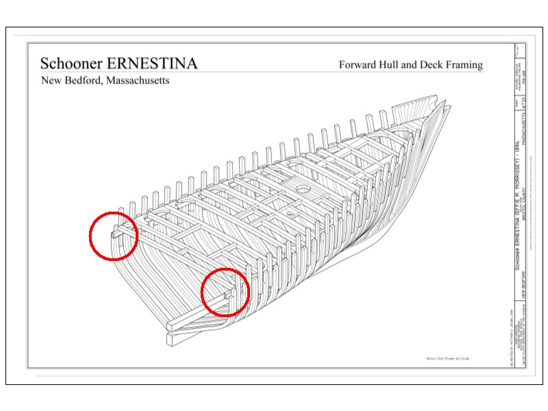
It could be that the stanchions are extensions of some of the frames not necessarily separate pieces. See Ed Tosti's build of Young America. If not and they indeed are separate pieces, the following drawing of a schooner of 1896 shows one example of how they were set up between the frames. For the size If you have the width and moulded dimensions of the top timbers of the frames these may be a guide to the size of the stanchions. For sure the moulded dimension would be the same even if separate pieces not frame extensions. Looking at the photo of the MC held by the Cumberland County Museum in Nova Scotia, the bulwarks appear to run up to the cap rail, not open as you point out. Odd that the artist shows them exposed which was not uncommon on older vessels. Maybe just his interpretation unless she was so fitted at some point in her lifetime before the photo at the museum was taken. Hope this helps. Allan
-
Karl, The model is gorgeous. As the drawings are from Boudriot, I assume it is a French 74. I see some differences compared to English 74's, such as there are four tackles per gun on the lower deck versus three on the British 74's. The British 74's had 32 pounders, and I think the French had 36's so maybe that is the reason for the difference. Two training tackles would surely make it easier for the gun crew when they had to be used. Beautiful job!
-
This first photo is of a wood belaying pin that has been stained black and varnished. It is from the HMS Discovery 1925. The next one is from HMS Coriolanus 1876 and is made of metal and the paint long gone. The last one is from HMS Worcester 1860 and is wood, and very dark in color. I see no way of knowing for sure what was on Beagle, be it painted wood or metal or unpainted wood. If that is indeed the case, you probably cannot be faulted no matter what you choose, but based on contemporary models, wood color is probably most appropriate. If you go with brass you can darken them without making them totally black. Birchwood Technologies makes an antique brown gel for brass and copper that could be just the ticket for you. Allan
-
Bruce, Absolutely mesmerizing account. Thank you for posting this!! Allan
-
Patrick, not only is your attention to detail impressive, the execution in getting the details completed is just as impressive. Well done. Allan
- 756 replies
-
- 3
-

-
- galleon
- golden hind
- (and 2 more)
-
Your build is super. There is bashing, and then there is bashing. The fact that you went out of your way to get the NMM plans for Sherbourne is fantastic. Can't remember other kit builders doing this, but if they did, kudos to you and to them as well. Allan
- 1,039 replies
-
- 1
-

-
- ballahoo
- caldercraft
- (and 2 more)
-
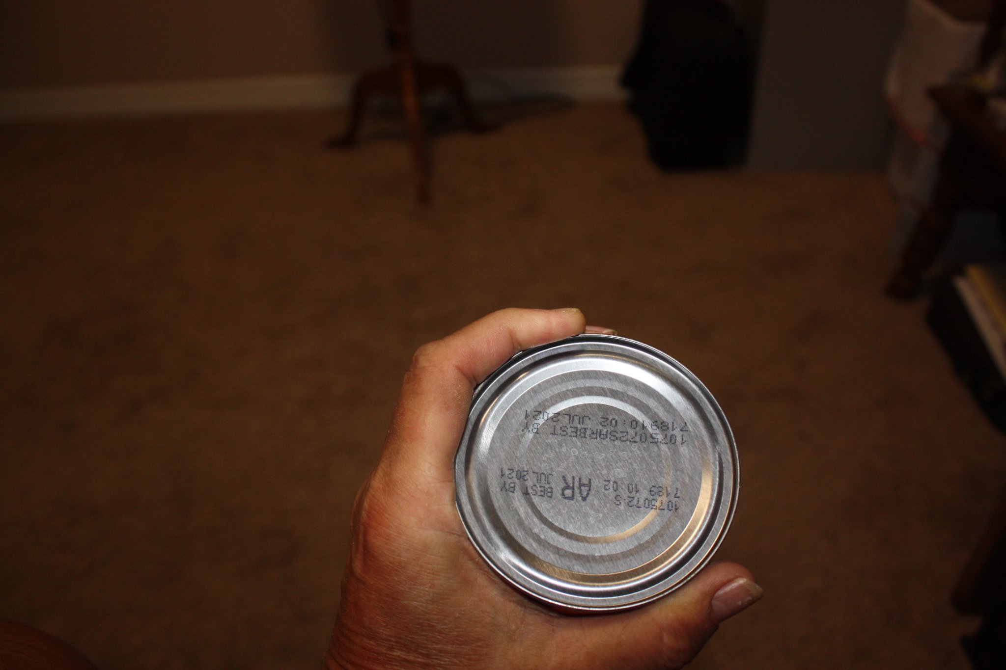
Lucien, I am curious to see the answer as well. The length, assuming your scale is 1:60 is about right at 19" so hopefully the shape is right. The handle diameter should be about 2" real world (0.033" or .84mm) This is very small and maybe weak if they are wood. For this size, you may be better off with brass pins that are painted a wood color. I scaled the top picture in CAD and the handle diameter is way oversized at about 3.5", nearly double what they should be. They do look better than most but once in a pin rack, they will not look right. As was posted quite a while ago by another member, try to put your hand around a too large diameter rod and you will understand better why this would not work. The photo has a can 3.25" diameter so it would be even more uncomfortable and hard to hold a pin that is 3.5" diameter. Again, the ones in the photo do look better than many other but they are really not close to scale. Allan

-
Welcome aboard MSW David!! You choices are extremely well thought out. So many (including me) start off with a 1st rate ship of the line and struggle for months. Per the above, do start a build log and you will have a lot of help from the membership if you hit a bump in the road. Allan
-
Gary, First and foremost, she is looking great!! Not 100% sure about Confederacy, but raised letters on the stern are a modeling thing, not what was really done as they were painted on if the name was even there which was not normally the case. The names of the ships were painted on British ships only for a short period in the late 18th century but then stopped by order of the Admiralty as they wanted to give as little information to the enemy as possible. Maybe too late for your Confederacy as they look to be glued on, but something to consider for the next project. Again, very nice work!! Allan
-
WG, These have to be the best coiled ropes at this small scale I have seen. WELL done!!! Allan
- 950 replies
-
- 2
-
-
-
- syren
- model shipways
- (and 1 more)
-
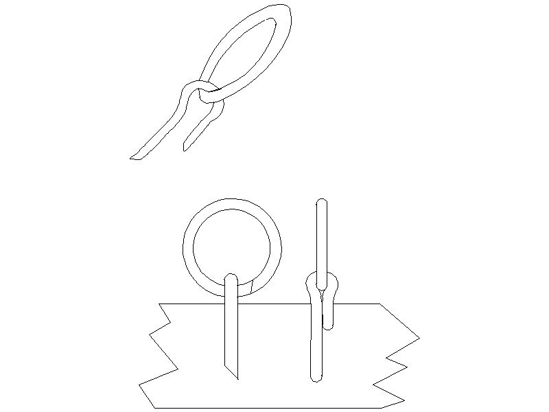
Do the instructions give each size an ID number and then show where they go on the model? For carronades, I don't have information for American ships, but for the British, it varied with time, size, and design of the carronade carriage. Can you post a picture of the carronade carriages and carronades? The split rings should be soldered into a solid ring regardless of where they are being used. This is near impossible to do in-place so best to do the soldering before using them. Once soldered they can be cleaned up and blackened chemically or with paint. Hopefully the rough sketch below will explain better than words. Allan
-
Glenn, Meticulous build and very clear and informative photographs that not only help others, but inspire everyone of us. Well done. Allan
-
BE, Going back a few days/weeks, how did you silver solder the beads on the crown without any falling off as you soldered the next ones? I have used several different solders with three different melt points, but that would not work with so many beads. I sometimes use clips as heat sinks on the first items soldered, but on this small and delicate piece, I would love to hear your secret. The entire project looks great ! Allan
-
The build is magnificent overall, but I especially like your blocks. Amazing what can be done with modern tools compared to the old days. The problem is that every time I see what can be done by folks like you, it makes me want to spend money on the latest technology. Thankfully my accountant/admiral/wife asks me to wait and see if I really need it. Saved us LOTS of money over the years. Allan
- 589 replies
-
- 5
-
-
- le gros ventre
- cargo
- (and 1 more)
-
As always your work is an inspiration to those interested in working with watercolors. Beautiful. Allan
-
Hi CC, Welcome to MSW. You now have upwards of 40,000 advisors to answer any questions you have in your journey. Allan
-
Welcome to the fray Bob!!! Allan
-
Kent Years ago I found that these are limited to a few diameters and do not work any better than a simple steel draw plate. Most treenails are from 1" to 1.5" diameter so scale sizes for 1:48 would be from 0.02 to 0.03 and for 1:64, they would be .015 to .023. Obviously smaller needs for smaller scales, but treenails on scales less than 1:64 are VERY difficult to make with any device and usually wind up making the model look like it has the measles. There are so many models shown here that are excellent, then some are ruined with out of scale treenails. They serve little purpose for strength unless you use bamboo which works beautifully with a good quality draw plate such as the ones offered by one of our sponsors, Jim Byrnes. I am only speaking from my own experience. Others have gone to monofilament and other solutions. Again, be wary of making oversized trennals, regardless of the method you choose. Allan