allanyed
-
Posts
8,149 -
Joined
-
Last visited
Content Type
Profiles
Forums
Gallery
Events
Everything posted by allanyed
-
 I lived about 4 miles from the battle grounds for over 30 years and the terrain is really not bad compared to Pennsylvania and New York as there are only small hills and valleys so this seems unusual unless this was a habitual problem at that time regardless of the terrain. Then again, the roads meander with no straight lines even today so it was probably worse back then getting around with whatever roads and paths that existed. There are a few streams but no rivers and such to use as land marks which could have added to the difficulty. Could you direct us to where we can find this account? Right next to the battle grounds is what is now called the Molly Pitcher creek, the nickname for Mary Ludwig Hays who reputedly brought water to the colonial soldiers, including her husband. Allan
 -
Hi Bill, If you would be so kind please post some photos of the barrels. It sounds like you have a different kit than Iseaz as the ones he shows don't look remotely close to any cannons from the 17th century or later centuries for that matter. It would great to see decent quality, accurately made, cannons in a kit. TIA Allan
-
Do let us know what they do to help you. It would be a shame to be stuck with those guns if the rest of the model is a good one!! Allan
-
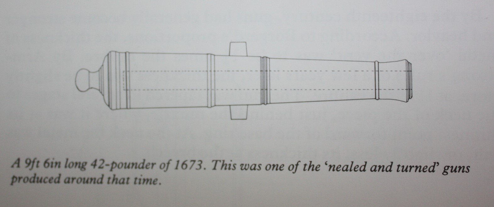
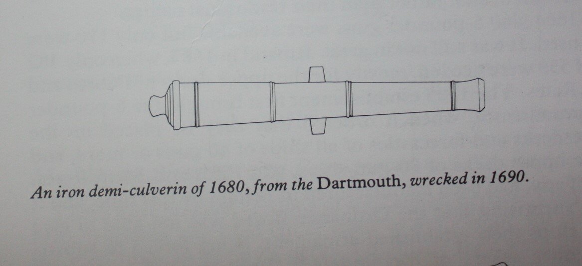
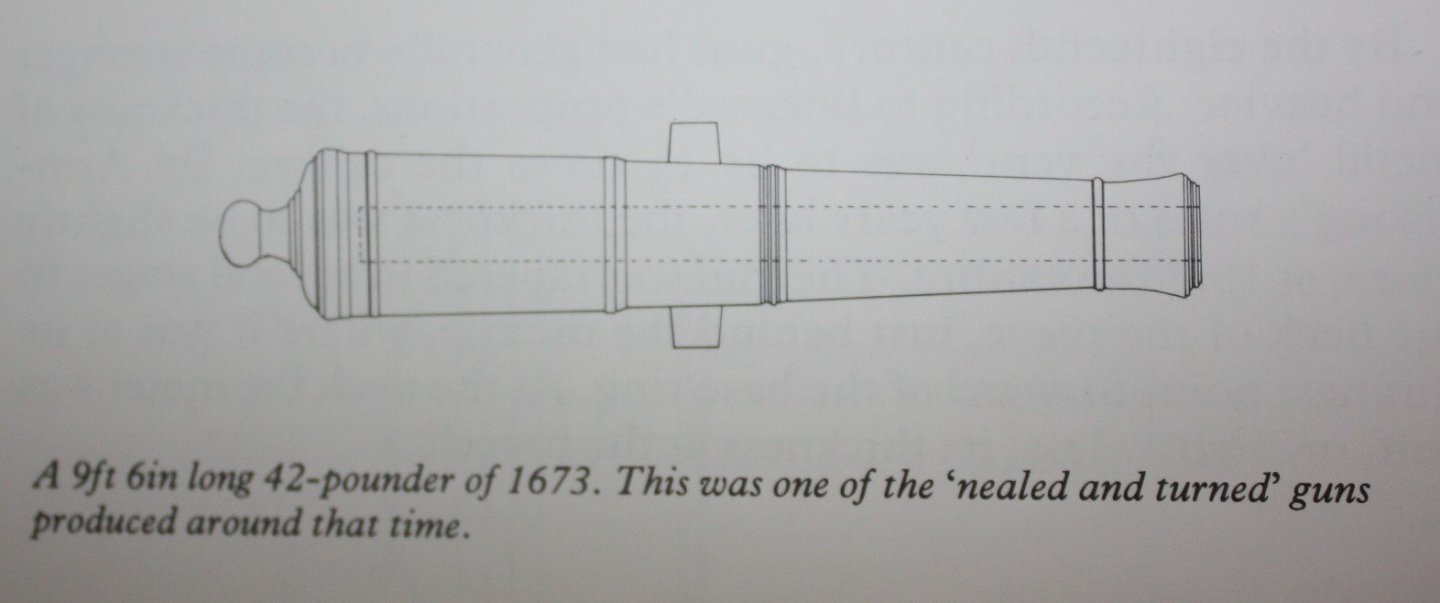
Hate to say it but given the rest of the model is faithful to the Prince, maybe consider replacing the cannon. The rings are out of scale and there are seven instead of five which would be appropriate for the 17th century. The trunnions are in the wrong place and they are the wrong shape (they should be tapered) for the 17th century and far too long, there is no taper to the barrel and so forth. If you can, make your own or send STL drawings of cannon for the 17th century in the dimensions for each of the calibers that you need to a 3D printer and get some resin printed pieces. Most, not all, brass and cast cannon from suppliers will be the wrong shape and size as very few offer guns for the late 17th century. The following drawings found in Lavery' s Arming and Fitting of English Ships of War, pages 100&102 show the difference between what the kit gave you and what they actually looked like. Allan
-
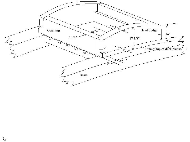
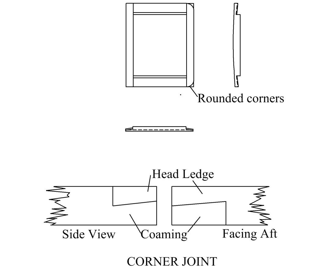
You do not need any power tools to make the joints, after all, the beautiful contemporary models we see were made with hand tools. A set of well honed chisels and back saw is about all you need to make the corner joints. Lady Nelson was built in 1798 so she would not have lap joints per se. The type of joint you need for this era can be seen in the following pics. You can see more detail on this type of joint in the Euryalus books and the TFFM series. The first pic with dimensions happens to be for the Euryalus, so you may need to adjust for Lady Nelson or other vessels. Allan
-
Minimum plank length
allanyed replied to Don Case's topic in Building, Framing, Planking and plating a ships hull and deck
That is odd. I am PMing you to see if it goes through. Allan -
John, Take a look at the June 1 post in the Charles Galley build log in scratch builds 1501-1750. There are also detailed descriptions in Frolich's The Art of Ship Modeling. One of the keys is to make the gratings close to the size you want, then make the coamings and head ledges to fit around the grating to assure a tight fight and not have to worry about open holes next to the head ledges or coamings. Allan
-
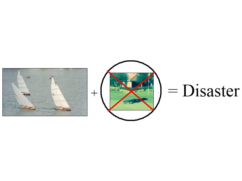
IR3, your workmanship is spectacular and to make it better, she will have the gear to be a working piece. We live on a small lake and I have thought about a small RC boat project but the gators here get to well over 10 feet and if one of them happened by while I was at play with the boat, it might think this an easy meal, both the boat or me, so I will stick with static models for now. The photo on the right side of the equation below was taken on our community golf course. Fun times!! Allan
-
Bonjour Alex!!! Welcome aboard. I love that you completed your first scratch build and have learned a lot and also realize there is more to learn. A warning for you...... for most of us, there is ALWAYS something new to learn which is a great thing. A good day is when I see something new here at MSW that will help me on my projects. Allan
-
I am enjoying your build log, thank you very much for posting the photos. Down the road, maybe consider copper instead of brass where possible and you can blacken in situ with liver of sulfur without discoloring the wood. Copper wire can also be used in lieu of nails and a head formed with a cup punch. Most punch diameters such as from Brownell are over-scale for our models, but the tip can be reduced in diameter on a lathe to whatever diameter is required. Allan
-
ancre La Belle 1684 by Oliver1973 - 1/36
allanyed replied to Oliver1973's topic in - Build logs for subjects built 1501 - 1750
Oliver, you should be very proud of your work!!! It is very nice seeing such tight fits and attention to detail. I know this takes an inordinate amount of time to do it right, but it is so evident in your build that you took the time to do so. Allan -
We all do Jim 😁. Several clubs are asking their members to sign on and Zoom meetings are being held with Adam and other groups to generate the signatures that are needed. Tell your friends, pass the word. If even 100 people get 2 others to sign on and then those two each do the same and so forth, it should not take too long to get the 10,000 signups needed to make this happen.
-
Welcome to MSW Bo, The best paints in my own experience are tubed artist acrylics. I would also consider an over spray of a matte finish UV protecting urethane or similar top coat. Perhaps the Occre supplied paints are top quality artist acrylics as well but they may be like the cheap bottled acrylics. I have used those bottled paints in the past and they seemed to be OK at the time, but when I went to good quality tubed artist acrylics I learned the bottled stuff is not nearly as good. As usual, lower price, lower quality. Allan
-
Ulises, I suspect Piet is correct. Also, which version, 1637 (beam 46'6"; keel 127') 1660 (beam 47' 6"; keel 127') or 1685, (beam 48'4"; length on the gun deck -not the keel- 167' 9") Assume the length of her gundeck was 51.13 meters after her rebuild in 1683. (51.13)X1000/1100 = scale of 46.48. Both kits mention the ship being originally built in 1637 but neither states which version they are supposedly replicating in the kit. If you look at the contemporary drawing held at RMG (Sovereign of the Seas (1637) (ZAZ0047) the length from the aft of the taffrail to the tip of the figure head is 2,595" If this length was 1100mm, the scale would be 1:60. Based on this, I think both kits are probably using the sprit and aft tip of the mizzen yard which of course varied with how it was set. If you can find the maximum beam of the hull of model, you can figure out the real scale of the model more easily. Allan
-
No worries, there are a lot of kits that are loaded with mistakes. Oversized belaying pins and unrealistic looking gratings and copper plating on the hull seem to be the most common items that stand out in a not so good way. Thankfully there are some excellent kits on the market now thanks to several designers with a thorough knowledge of how the ships actually looked so we all can benefit. Allan
-
O.N. She is lovely, very neat and clean work throughout. I realize you were relegated to using what the kit offers, but I would like to know if it provided the parrels for the cross jack yard on the mizzen. The reason I ask, is that on English ships the cross jack had rope slings until the mid 19th century, then chain slings, but never did they have parrels. Thanks Allan
-
Stitching sails with sewing machine
allanyed replied to Jorge Hedges's topic in Masting, rigging and sails
Ted, Thanks for the reply and photos. The reef point method is pretty much the method I use as well. I do wet the points with matte medium then pull to straighten them while it dries which takes a few minutes. Well done! Allan -
Minimum plank length
allanyed replied to Don Case's topic in Building, Framing, Planking and plating a ships hull and deck
Ted, What you say makes sense, but actually short pieces were indeed in the bow and stern at times. On the Squirrel, there were five ceiling strakes with the forward most planks between 6' 3" and 11' 0". There were also seven strakes of the outboard planking where the forward most pieces were from 7' 6" to 11' 0" long. These go from the strake just above the garboard up to even with forecastle. Allan -
Minimum plank length
allanyed replied to Don Case's topic in Building, Framing, Planking and plating a ships hull and deck
Don, I don't know if it is a good idea to use house roofing rules for building a ship. 2X8 roof trusses are typically about 1.6 inches thick where as frames are sided in the 10 to 12 inch range, sometimes more. Roof trusses are typically on 16 inch centers if I remember correctly so they are 14.4 inches asunder, but there is only about an inch or two between frames. Even for deck planking, the ledges are no more than 9 inches asunder. Plywood was first patented before Discovery was built but I doubt it was used for her planking. For a clearer drawing of Squirrel or some others you can purchase a high res image from NMM. If you are interested in a high res printed version of the planking expansion for Squirrel from NMM, PM me as I no longer have need of my printed set of Squirrel drawings. The drawing has a scaled rule at the bottom and the station lines are there as well. Every plank inboard and outboard has the plank length written on it. If you study the framing plan and compare it with the planking expansion drawing you can determine how many frames each plank crosses. I just took a look at the plans and it only took a few seconds to determine how many frames the shortest pieces crossed. Allan -
Lawn, A very warm welcome to MSW. If you have never built a model ship before, you may want to consider something less complex than a rated ship for your first project. With hundreds of running rigging lines it is difficult to just rig them and fix them in place let alone rig them so they are working tackle. Just getting to belay, release and re-belay one or two lines would be cumbersome at best. Still, I am sure everyone here wishes you good fortune. I really hope this works as it will be a very interesting journey for us to follow. Allan
-
Stitching sails with sewing machine
allanyed replied to Jorge Hedges's topic in Masting, rigging and sails
Thank you for posting this. I did a quick look at lawn cloth (100% cotton) on line and it is a woven fabric which usually is terrible for model ship sails as they are so out of scale. But, yours look really good. Your seams and panels are right on scale. What size thread did you use for the points? They look to be about the same as the bolt rope but it may be the photo. Do you happen to know the thread count of the fabric? Thanks again for posting this. Allan -
I did find what looks like a small poop on the St. Albans, 1687 and what looks definitely like a poop on the contemporary model of Mourdant 1671 in Endsor's Master Shipwright's Secrets, but all the others he shows are as you describe Druxey, a small hutch-like unit or with nothing at all. Endsor does point out that the model of the Mourdant is not without mistakes. As an example he compares the location of the forward channel wales, which is not normal on the model, and three separate drawings by Van De Velde showing them positioned as was normal at that time. He mentions that it is highly unlikely that VdV would have made the same mistake three times even given the caveat that VdV was not always perfect in his depictions. Allan
-
Excellent point Bruce and this could very well be the case. Drawings by Van de Velde do not show a poop and photos of similar vessels show a mix, some with, some without. The clearance from the decks to the overheads are all about 5 feet or a bit more elsewhere. Thanks!!!
-
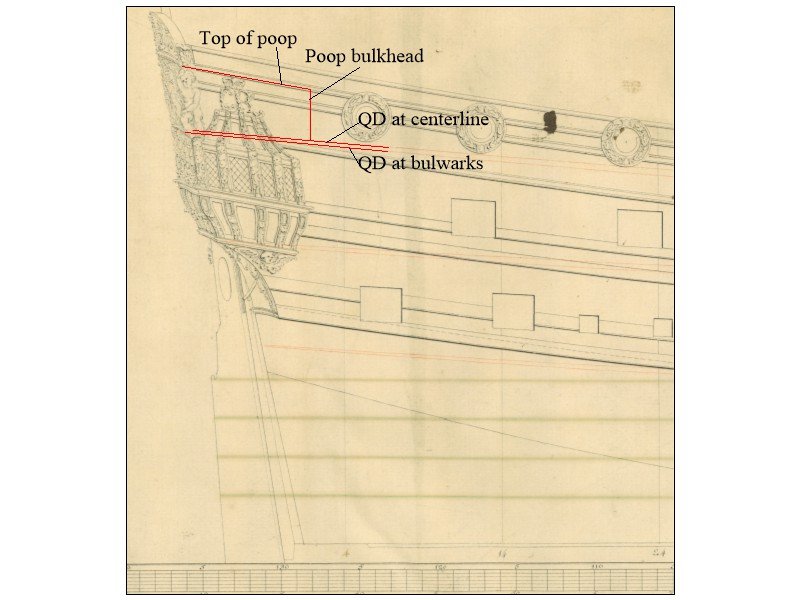
Looking at original drawing of two ships that were to be built about 1678 following the Charles Galley, the poop looks to be very short. It is about 12" shorter than that of other ships of the era found in Richard Endsor's books and other sources I have checked. This includes his scaled painting of the Charles Galley which has the top of the poop at about 54". The following shows the QD and poop lines in red. When scaled the height of the poop bulkhead about 42-43" high. The rounding of the top of poop is not shown so if this is the outboard height and rounding is added, the height would still be only about 50" at the center line as the rounding of the top of the poop for this size vessel was about 8" to 9". Has anyone seen such a short poop or have I missed something? (Note: the red lines on the drawing did not show up well when I loaded it here so I traced over them in red so they would show better.) TIA Allan
-
Longridge's book is great and extremely useful for the late 18th and even into the early 19th century. This was the second book to go into my modeling library going back to the '70s and I still reference it at times today when appropriate. But, Tom's focus is 17th century so maybe not so useful as others that have been listed. Scantlings for the ship itself as well as the masting and rigging were quite different in the 17th century compared to the time of Victory Allan