
DONATION DRIVE - SUPPORT MSW - DO YOUR PART TO KEEP THIS GREAT FORUM GOING!
×


allanyed
-
Posts
8,149 -
Joined
-
Last visited
Content Type
Profiles
Forums
Gallery
Events
Everything posted by allanyed
-
 Also consider purchasing a copy of Lees' Masting and Rigging which will give you a lot of information. For your time period I rely mostly on both Lees' and Anderson's books. Lees gives a lot of detailed illustrations compared to Anderson, but both are extremely useful. Closest I ever got to a carrier was when I was stuck on an AO for a few days tp run casualty drills in the engine room while doing Navy Reserve duty and we spent a day refueling Saratoga in 1971. She was small compared to new carriers but it was awesome, especially watching flight ops when they were landing aircraft . Submarines, ohhhh the claustrophobia would be a killer compared to the surface merchant vessels I had the good fortune to sail aboard. Thank you very much for your service Cliff.
 -
Marcus, Similar to Monfeld's formulas, and lacking other information, the formulas in Lees Masting and Rigging will give you every mast and spar dimension, and rope circumference from 1625 to 1860. He starts with formulas for various time periods to find the main mast length, then all mast and spar dimensions as well as all rope circumferences can be found easily. As has been reviewed here at MSW recently, go to the Articles Data base here at MSW and bring up Danny Vadas' spread sheet. It appears to be the same information that Lees gives with one exception. The Vadas spread sheet cannot be used for the period from 1670-1711 as his base formula was not done correctly so all dimensions that follow are wrong as well for this time period. If you have a vessel in that time period, Lees formulas work.
- 19 replies
-
- 3
-

-
- running rigging
- standing rigging
- (and 1 more)
-
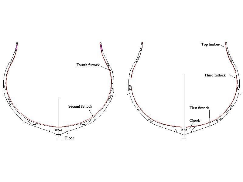
Don, The grain is important but keep in mind there are only several pieces for each frame. One has a floor, second futtock on each side, and fourth futtock and/or top timber on each side depending on the size of the ship. Look at the drawing below which was posted earlier in response to another question you had to get an idea. These are from a 50 gun ship of 1695, but will give you an idea on the size of each piece. In the case of the first futtocks, the contract for this ship stated that the futtocks should reach to 20 inches from the keel and each to be 12 feet to the where they meet the respective third futtocks. The floors would be even longer. Druxey gave you the information you need for the size of the chocks themselves. Use of chocks versus scarphs, depends in part on when the ship was built. For Discovery, chocks would be likely for each joint, except, possibly, for the top timbers which may have been scarphed to the futtock below. Hopefully others will have more definitive contemporary information. Goodwin shows only scarphs for 1650 to 1710 in The Construction and Fitting of English Man of War, page 14, then chocks (and scarph at the top timber) from 1710 to 1811. In The Restoration Warship, page 44, Endsor shows chocks being used based on The Bends of a Ship by Thomas Gagge, c. 1680. Goodwin goes on to explain that things changed with the Seppings system about 1811 but this is far past Resolution so no need to get into it here. Cheers

-
Don, Take note of the depth as well as the length of the chocks. How did you come up with the length of the floor and each of futtocks? They seem to be very short or it may be that the chocks are so long. Lacking other contemporary information such as a contract or drawing specific to your project, you could use the drawing that Craig posted as a guide. You can also get a lot of useful information from Kroum Batchvarov's doctoral thesis on framing. If you have problems finding and downloading it on the internet send me your email address on a PM and I can forward the pdf to you.
-
Hi Cliff, Welcome to MSW. it would be great if you posted a little intro about yourself on the new members forum. 😀 Have you looked at all the build logs of the Sovereign of the Seas in the build log sections? There are quite a few and may help you in your journey. Also, you should consider starting a build log once you get rolling. Sounds like you may already have a kit on the project you are working. Which brand of kit is it and does it have rigging plans included? If you have not yet purchased the kit, the logs may help you decide. With such a huge project, is it safe to assume you have built other ships already as SotS would be a frustrating first project. Again, welcome to MSW
-
Arnold, CA gluing the end of the line to be used as you mentioned above is a good thing to do, more so than using a wire threader. Once the CA has dried, use a scalpel to slice it to create a sharp point. I like the Swann Morton blades and holders, but there are others from which to choose as well. Even the smallest line can be treated this way, yielding a needle point to push through the hole in the block.
-
Either way is not so bad. I have often done the same thing. I have not seen any posts on your log for the past two weeks though. Maybe give it a another try. Better to ask twice and get a response from one forum than post on one forum and get no responses 😁
-
Another 34 frames is good practice for future builds!!! Look at all the experience you are gaining from asking and then doing, and think about how much more confident you will be on the next project. You are getting information from hundreds of years of collective experience from the members here. Many of us wish we had had this kind of access to information when we were on our first projects, so know that you are a lucky guy.
-
Moab, do they say what kind of boxwood it is? Thanks!!!!
-
Keith, VERY interesting use of tape!!! Any idea how well it will hold up for the long haul? Would hate to see it lifting after some years. Joe, have you looked at brass and/or copper sheets from McMaster Carr? They have sheets and bars of brass down to 0.005 thick. A package of six 4"X10" sheets that are 0.005 thick is $23.49 and 0.01 is $27.19 for six sheets.
-
Don, This may help understand a little better. These are two frames that sit next to each other.
-
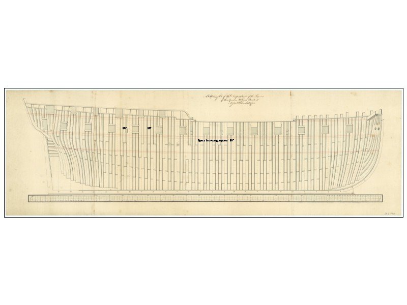
Hi Don I cannot speak for ships of other than English, but for those, simply put, R&S includes two frames and the small space between them and the next pair. There is no big gap between frames. Goodwin explains as follows on page 13 in The Construction and Fitting of English Man of War. ....stringent rules establish the distances between each 'main' frame so that this (ventilation) could be achieved. This was known as the 'room and space' provision, and measured the distance between the face edge of one complete (or main) frame and the equivalent face edge of the next main frame. The measurement can be roughly estimated as twice the fore an aft breadth of a single frame plus between 2in and 6in for the overall small spaces between the filling frames and and main frame. This is a bit difficult to be clear in words. Look for drawings such as those posted above which explain the lay of frames as they should be. The drawing above is contemporary and correct. If you are looking at contemporary models, they are usually "admiralty style" and do not have frames laid as they were on the actual ships themselves so of no use in figuring R&S. I suggest you pick up a copy of Goodwin's book as it is a great source on the basics of English warship construction between 1650 and 1850.
-
Don, The spacing between ports was not always the same. It could vary by as much as 10" round the area of the main mast. The space between frames for the ports themselves for a given deck on a given vessel was always the same so there was no need to cut into a frame as you show, thus weakening it. The frames were reduced in siding as you went up each futtock and they were offset as well, to create the proper width between frames so each gun port on a given deck was the same. There were small (about 2" deep) mortises cut into the frames for the sills. The sills sometimes had a birdsmouth mortise and at other times an angle mortise. This varied from ship to ship as some had angled mortises for both the upper and lower sills. The following is just one example, but there are many more that can be found at https://commons.wikimedia.org/wiki/Category:Ship_plans_of_the_Royal_Museums_Greenwich as well as the NMM site. This particular one was taken from the commons.wiki site as it is a high res version. Even with the low res versions you can download for free from NMM, you can see that the space between ports is sometimes the same, sometime not. You can also see a variety of the offset frame construction so no big chunk needs to be removed from any frame. For a much clearer look at the vessel drawing below go to https://commons.wikimedia.org/w/index.php?title=Category:Ship_plans_of_the_Royal_Museums_Greenwich&fileuntil='Impregnable'+(1810)+RMG+J1643.png#/media/File:'Aquilon'_(1786),_(also_spelt_Aquillon_or_Acquillon)_RMG_J7958.png The spacing between ports on this vessel happens to be consistent. Hope this helps.
-
There HAS to be an IT guy in the 40K members here that can help you. Where are you gals and guys???? Dave needs help!!!
-
Glue question
allanyed replied to Peanut6's topic in Building, Framing, Planking and plating a ships hull and deck
I agree with all of the above regarding using carpenter's glue versus white glue. Based on my own experience it generally takes more time to prepare the next piece while the glue is curing on the previous piece, but in a nutshell, for me, light stress-5 minutes or less; medium stress- 20 minutes is plenty; an hour is more than enough for everything else. If the stress is still too much, something is probably wrong with the fit/shape of the parts, not the glue. -
Looks like the same or very similar material. The site I gave above has weight of the paper as well so you can do a conversion and see if they are similar or perhaps exactly the same.
-
Mike, It does not really have sources. Check out https://sigmfg.com/products/sig-silkspan-tissue which is what I used. You can also go to their home page and click on catalogs, SIG, then scroll to page 86 for more options. What I find strange is that the material I bought SIGST001, is not listed in the catalog. They may have changed code numbers. You can get prices in dollars, Euros or other currencies on their site.
-
John I agree with the previous post from VtH. If you have the tools, you could make your own and won't have to use walnut which is really not the best wood for a ship model even though many kits use it. The color is usually inconsistent and rather dark and it is much to porous unless you are using black walnut which is less porous. Walnut is a respiratory irritant and actually causes rashes on some people as it has natural herbicides (all walnut species have jugalone which is a toxic compound) that fight off the growth of other plants near by. Ma nature does not forget plants when it comes to self preservation. If you must use walnut and have to do any sanding, an N95 mask is highly recommended and for any wood sanding it is best to have a dust collection system running at the spot where you are sanding to collect most of the particles. Even hanging the hose of a shop vac a few inches from where you are sanding works well. I love walnut for furniture and squares of a chess board as well as jewelers boxes, but models, not so much.
-
Roger, Cad indeed makes things easier, for me at least, and I am very very far from being an expert. Drawing the station lines, then paralleling each with an inboard line that is the moulded dimension of the frames less than the station line is all it takes. Not sure this would be so easy using water lines, but probably should work. As to the plug itself, water lines or station lines both work so it comes down to the builder's preference. I see advantages to both methods.
- 433 replies
-
- 3
-
-
- open boat
- small boat
- (and 1 more)
-
If the area is to be painted or coppered, filler should work. If not, I would remove the outer layer of planking for those strakes in question from the stern post to the first butts forward for each strake. You could then fill and fix the inner layer with filler or new pieces of plank, then put new planking for the second layer. It looks like the ends of the planks get narrower which is opposite of what they would normally be. May be the camera angle, but just curious about this.
-
This is the screen that you should have. The "New Build" button, second from the left on top is what needs to be hit to get the process started. Cheers

-
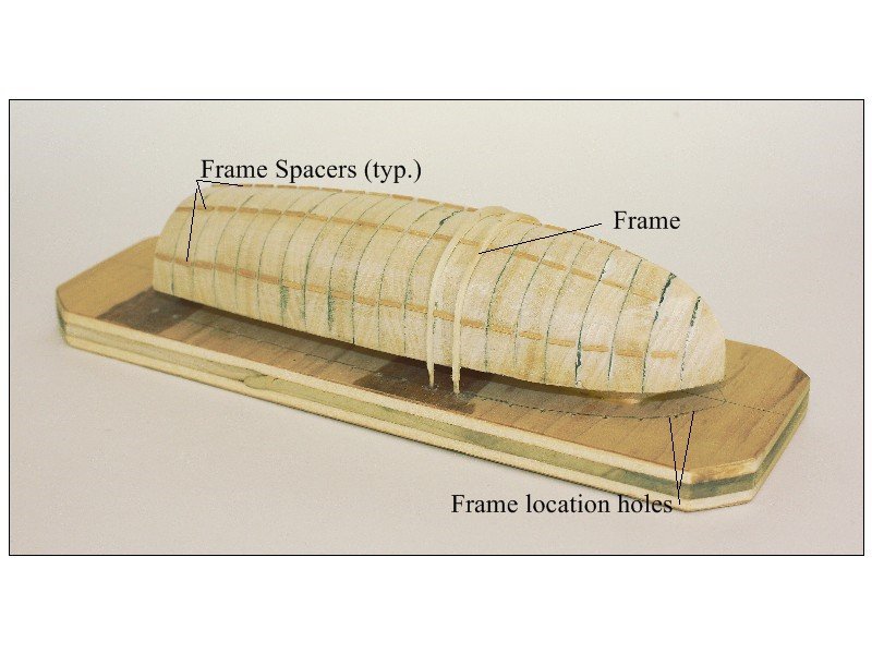
David, This is an excellent build log and great to see. Is there a reason you prefer water lines rather than station lines for making pieces for the plug? I can see the waterlines giving some ease in shaping with the grain, but is there any other advantage? Is there a reason you prefer making grooves to hold the frames in the plug? I found the grooves to be very possessive of the frames and do not like to let them go when it is time to remove the shell from the plug. The dreaded CRACK when removing the shell is not a fun sound to hear as you pointed out as it creates extra work. I switched to an alternative method quite a few years ago. It does require a little bit of editing of the plug dimensions to the inside of the frame but have never had one stick to the plug, even with all frames and planking in place. Pic below. The spacers keep all the frames in place while the planking goes on just as the grooves would do this. I REALLY like the substantial grove at the bow and stern for the stem and deadwood and the use of gesso. Thank you for sharing your methods and experience!!
- 433 replies
-
- 10
-
-
- open boat
- small boat
- (and 1 more)
-
Warm welcome to MSW Ken. LOVE your art work and with your eye for detail, you should do very well with Syren. LOTS of help to be had here from the membership which incudes artists that can relate to you and your endeavor.
-
Dave, there is no edit button. Click on "New Build" at the top of the page. Scroll down to the bottom of the page and enter your scale. Go back to the top of the page and hit "Enter Data."
-
Mike, I do not recall ever seeing a sail with metal rods. Are you speaking about using metal wire of some sort to keep the sails for the model looking billowed rather than using a bolt rope? Merci bien
