


allanyed
-
Posts
8,149 -
Joined
-
Last visited
Content Type
Profiles
Forums
Gallery
Events
Everything posted by allanyed
-
 Michael, It is not advisable to post email addresses as the moderators have mentioned numerous times in the past as it will be spammed. Allan
- 749 replies
-
- 2
-

-
- albertic
- ocean liner
- (and 2 more)
-
Topsail schooner sail plans and rigging
allanyed replied to Dr PR's topic in Masting, rigging and sails
Phil, Kudos for doing so much homework to get things right. https://www.youtube.com/watch?v=0mfJn604GT4 Allan- 104 replies
-
- 1
-
-
- schooner rigging
- Topsail schooner
- (and 1 more)
-
Dave, Regarding the rope, it sounds like you are talking about the strops around the blocks. Assuming the scale of your Amati Bounty is 1:60, and the cannon are four pounders, these would all be single blocks about 6" long so they would be 0.10 inches long (2.5mm) You can use the following formula to get the size of the strop, assuming it is about the same size as the line that runs through the block. There is a lot more to it, but for this scale, it is going to be pretty close. The length of the block is about 8 times the width of the sheave hole so the rope would be less than 3/4" diameter for a 6" block. 0.75"/60 = 0.0125 diameter. 20 gage wire is 0.03" so triple the diameter you need. 28 gage (AWG) is 0.0126 so pretty much dead on. This is single strand. I suspect darkened 28 gage single strand would look realistic but if you really want to twist wire into rope of the proper size you would probably need 32 gage or perhaps smaller for a three strand rope-like finish. I am looking forward to seeing your end results as this sounds like a solution to keep in the files for future use. Allan
-
If these cannon are from the 18th century, if you want realism, they should be black and the carriages either wood or red in color. The trucks can be the color of wood as well or I have seen these painted black at times. Allan
-
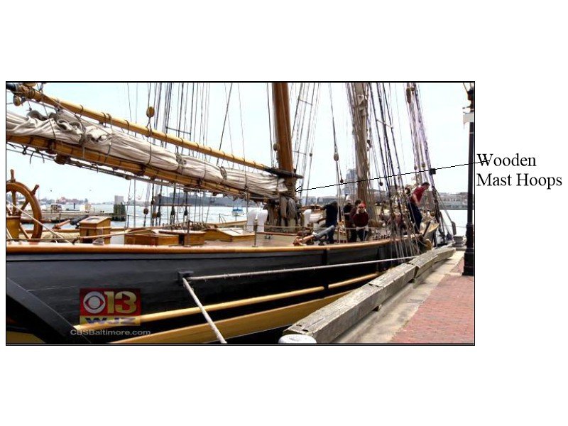
Michel, I think the rings on the masts are too many to be wooldings which were usually made of rope. Even large vessels had fewer wooldings than the drawing shows. I wonder if the drawing is wrong and these should be wooden mast hoops to which the foreside of the sail is tied so it can be lowered and raised. If these are wooldings, the gaff would be difficult or impossible to lower without it getting hung up at each woolding. See the photo below and you can see the wooden mast hoops on the P of B II. Allan
-
John (Dr. Jeckyl) Do you know what the wire is made of? The reason I ask, is if the coating can be scraped off so it can be silver and/or soft soldered. Thanks Allan
-
Dave , Liver of sulfur is good on copper, not on brass in my experience. The big advantage is that it can be watered down and applied to the piece after it is in place without discoloring the wood. Do look at Ed Tosti's Young America build log as he describes its use in some detail with good photos. I would like to know if anyone knows of a blackening agent that will blacken copper and soft solder as well as brass and silver solder. Allan
-
Dave, I prefer copper to brass if at all possible You can blacken it AFTER it is installed so you are not scratching/rubbing off the blackening, be it paint or Jax or any other blackening agent when handling, twisting, etc. Once the part is in place you can blacken it with liver of sulfur. Be sure your copper is uncoated so you will not have to clean it with acetone or pickling solution or some such. Look at Ed Tosti's log on the clipper Young America and he explains using it. I tried it and I am completely sold on it. There are times when brass is better if a stiff piece is needed as it is much harder than copper, but I use copper whenever possible. Copper also is easier to soft solder and it will be very strong, where as I prefer silver solder when I do use brass. Just as a FWIW, I am using soft solder paste and silver solder paste rather than hard pieces of solder. Much easier. Allan
-
Swann Morton for sure. Do a little web search on XActo versus Swann Morton blades and you will see that most, if not all, comments from those that have used both vote for the scalpels from SM. Allan
-
Is there a trick with Zap CA?
allanyed replied to Keithbrad80's topic in Modeling tools and Workshop Equipment
Another good reason not use CA when PVA or Epoxy can be used. Never had this problem with either in 45 years. 😀 Allan -
Whether or not you are putting sails on the model, for the lower masts, if there are boom saddles, these can go on first. Next make and slip the mast hoops onto the mast and they will all rest on each other loosely on top of the saddle for the time being. Next up are the trestle trees, hounds, cheeks, bibs and bolsters if they are present. If there are iron bands and battens they can be put on as well. I am guessing there are no wooldings as there are mast hoops that need to go up and down the mast, but if there are any around the cheeks, they can go on beforehand as well. Cap and cross trees can then be added as well as any eyebolts and blocks that hang from the cross trees and trestle tress. You can make and fit the top masts at this point as well, but they should not be set permanently in place until after the lower masts are stepped and the shrouds, swifters and lower stays, if present, are in place. All that is really needed is to look at what goes on these masts and add them in any order that will not prevent the next item from going on. Allan
-
If you have not run the line through the hull and want to represent the lead lining, you can paint a grey ring around the hole. It will not be noticed if you are building to a small scale, but if you are building at a large scale, it is a nice added touch of authenticity. Allan
-
Gratings
allanyed replied to DaveBaxt's topic in Discussion for a Ship's Deck Furniture, Guns, boats and other Fittings
Dave, One way is to glue together the outer ledges and battens on all four sides as these need to be a solid line, not with openings against the coamings or head ledges. You can then add dots of glue to the end of each grating ledge then glue in in place followed by gluing in the battens. If your build is a kit, the gratings may be mistakenly made of ledges and battens that are all notched but the assembly can be the same and will look fine. If you prefer to assemble everything dry you can then use artists' matte medium which dries clear and is waterproof rather than soaking the entire grating in a batch of glue and water which may cause it to distort and lose its rounding athwartships. Just brush it on the underside, but if a little comes through onto the top it can be sanded off once dry, but be careful not to flatten out the rounding. The sketch below is rather simplified but shows what I mean, I think :>) Allan
-
Try a test piece joint for this to see if you like it. My preferred method is that I mix a small drop of black acrylic paint with PVA carpenters' glue, just enough to make it dark grey or black, but not enough to negate the purpose of the glue itself. It leaves a distinct black seam and does not weaken the joint. If any has seeped out it can be scraped and then sanded. Black tissue like that found in craft stores is very thin but shows the line well and is porous enough that the glue penetrates and does not significantly weaken the joint in my experience. Allan
-
Ron, Thank you but while Chapelle is great and my "go to" book for schooners, he shows where the downhaul goes on the aft end of the gaff itself but nowhere does he show where it is belayed. He gives two choices for the main gaff downhaul or vangs , but not the fore gaff. I think I would be okay that it is the same rigging for Bluenose, but I don't see the downhaul on any of the rigging drawings I could find for her. I was hoping that with many Bluenose models built by members here, someone will have information. Allan
-
I have spent well over an hour going through books and drawings but cannot find any information on where the fore gaff downhaul or vang is belayed on any appropriate Gloucester fishing schooner that might apply to Ernestina/Effie M. Morriseey 1894. I have the information for the main gaff, but not the fore gaff. Any help will be very much appreciated. Allan
-
Shipman, Pick a boat and you will get answers for sure. There are scantlings by Steel and more information in Boats of Men of War by W.E. May Scantlings for boats of about 1800 that show main thwarts from 7" broad for a 16 foot cutter to 12 inches for main thwarts for a 32 foot longboat. Pinnaces and yawls were from 9" to 10" broad. Loose thwarts for a 16 foot cutter were 7" broad up to 9" broad for a 32 foot longboat. After thwarts ranged from 7" on a 16 foot yawl to 9" on all longboats. Forward thwarts ranged from 7" on a 16 foot yawls, to 9" on all launches and 10" on all longboats. Pick a boat and size and there is information available for each. Earlier scantlings give thicknesses of main and loose thwarts, but I could not find any dimensions for their breadth but would assume they would be similar to those in the 1800 scantlings. Allan
-
Chris, If you are scratching and it is a framed model you are taking on a huge project, good for you!!!! Which Agamemnon, 1781 or some other? I know there are all the scantlings you will need and good contemporary inboard profile drawings of her and her sisters. If this is a kit with POB, it will be interesting to see how you can do this cutaway as I am sure many builders would like to try this as well. Looking forward to seeing your progress on a build log. Allan
-
Jon, Lacking better information, I agree, Chapelle is my "go to" source. Even there, he gives multiple rigs for some lines showing that not all vessels were rigged exactly the same, even if those vessels were similar in size and type. 18 degrees -- no thank you. Allan
- 86 replies
-
- 4
-
-
- schooner
- effie m morrisey
- (and 1 more)
-
If the mast is set into a square hole in a corresponding mast step, the rigging will hold everything in place. If there is no such step and the mast can rotate, gluing is a good idea. While setting up the rigging, unless secured in some way, be it the square mortice in the step or glue, the mast may get turned a bit and the cross trees and platforms will not be square to the keel as they should be. Allan
-
Darren, I am not sure if there were standards, but there is some information available. This is not a straight forward thing. Which ship, year nation? The Lady Nelson that you list in your signature may have been different than rated ships as she was an armed survey vessel built in a private yard by John Dudman. Contemporary information for rated British ships is available and may be similar, if not the same, for Lady Nelson. If there were wales, some scantlings for rated ships are in the Establishments and can also be found in the Shipbuilder's Repository and Steel's Elements of Naval Architecture. They all give the thickness of the plank of the bottom as well, but not the widths. Some cross section drawings show the planks width, and there are planking expansion drawings that show the individual planks from which you can get an idea on the widths. Looking at the planking expansion drawing that I have of Squirrel (24), 1785, as one example, the widths were about 10" for the plank of the bottom midships. The strakes all tapered so the widths varied a lot from the dead flat to the bow (down to about 6.5" at the stem) and from the dead flat to the stern post (widening from 10" to over 11") From Steel and the SR the thick stuff above the wales was 13" wide, and the wales were anywhere from over 15" wide down to about 9.5" wide depending on the size of the ship. Also, depending on the ship and era, the wales could have been anchor stock or similar planking rather than strakes of planking found on the rest of the hull. The planking above the thickstuff for Squirrel is 8" and was different for various ship sizes. Lastly, ships contracted to private yards commonly had contracts with scantlings, including information regarding the planking. They were pretty detailed on the various thicknesses and gave some information on the widths as well. Sorry to hit you with maybe too much information, but if you can narrow things down to one ship, members can probably steer you to reliable sources for accurate information. Allan
-
"Seams" to be a standard dimension across the ocean for both seams and panels. Thanks gentlemen! Allan
-
Ref: Gloucester fishing schooner Ernestina nee Effie M. Morrissey 1894. I am trying to settle on a net spacing of the canvas sail panels, that is, the distance between seams. Given a seam of 2" the net distance for schooner Columbia is given by Chapelle as 20". He is also specific about the seam being 2" wide except on the periphery of the sail which is closer to 4". In doing a test piece, 20" looks to be very narrow. If anyone has information on the width of sail panels and can share, I would be grateful. Modern vessels are closer to 36" from what I have been able to find but I cannot find any information other than in Chapelle for the schooners of 100-130 years ago. Allan
-
Revolver Ocelot, or should we just call you Shalashaska? 😀 Welcome aboard MSW. It is great to have a "youngster" join our ranks!!! You will have access to thousands of mentors here so fear not regarding minimum experience, space, and tools. Allan
-
Ernestina Morrissey by Jond - FINISHED - 1:48
allanyed replied to Jond's topic in - Build logs for subjects built 1851 - 1900
Jon, Will there be a boom buffer on her rebuild? Pain in the neck to make and install and bigger pain to get the rings and block installed and the line rove. Continuing to love the diorama!!! Allan
