allanyed
-
Posts
8,149 -
Joined
-
Last visited
Content Type
Profiles
Forums
Gallery
Events
Everything posted by allanyed
-
 Todd, Have you considered making your own "Charlie Noble" . Guess the name is not appropriate here as the term came into being having been named for Captain Charles Noble about 1850 and Swift is circa 1805. It can be as simple as using a dowel if it is round and with hand saw, scalpel and sand paper you can do a credible job including making an offset if appropriate. Brass tubing can also be used if you want to tackle soldering. As for the anchors, your choice as long as an arm and fluke are hooked onto the rail and rigged to stay in place. They would not be just left loose. On some small vessels they may have actually been secured on deck when underway. Some folks like leaving one just hanging down. I am sure some member will have better information on the anchors. Allan
 -
Kees, First time checking in on your build log. OH MY, what a beautiful job you are doing, and a wonderfully detailed log. I have often thought about a model of one of the freighters I sailed on in the 60s. Your log tells me it can be done and gives me hope!! Allan
- 193 replies
-
- 1
-

-
- wilhelmina vii
- fishing
- (and 1 more)
-
dolphin striker
allanyed replied to D J B's topic in Building, Framing, Planking and plating a ships hull and deck
Darrell, Hopefully the following will be of some help. Not sure which, if any, would be totally correct, but you get to pick your poison unless a member has something more concrete for a BC in the early 1800s. Allan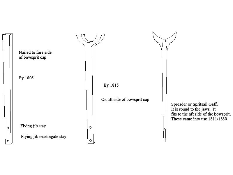
-
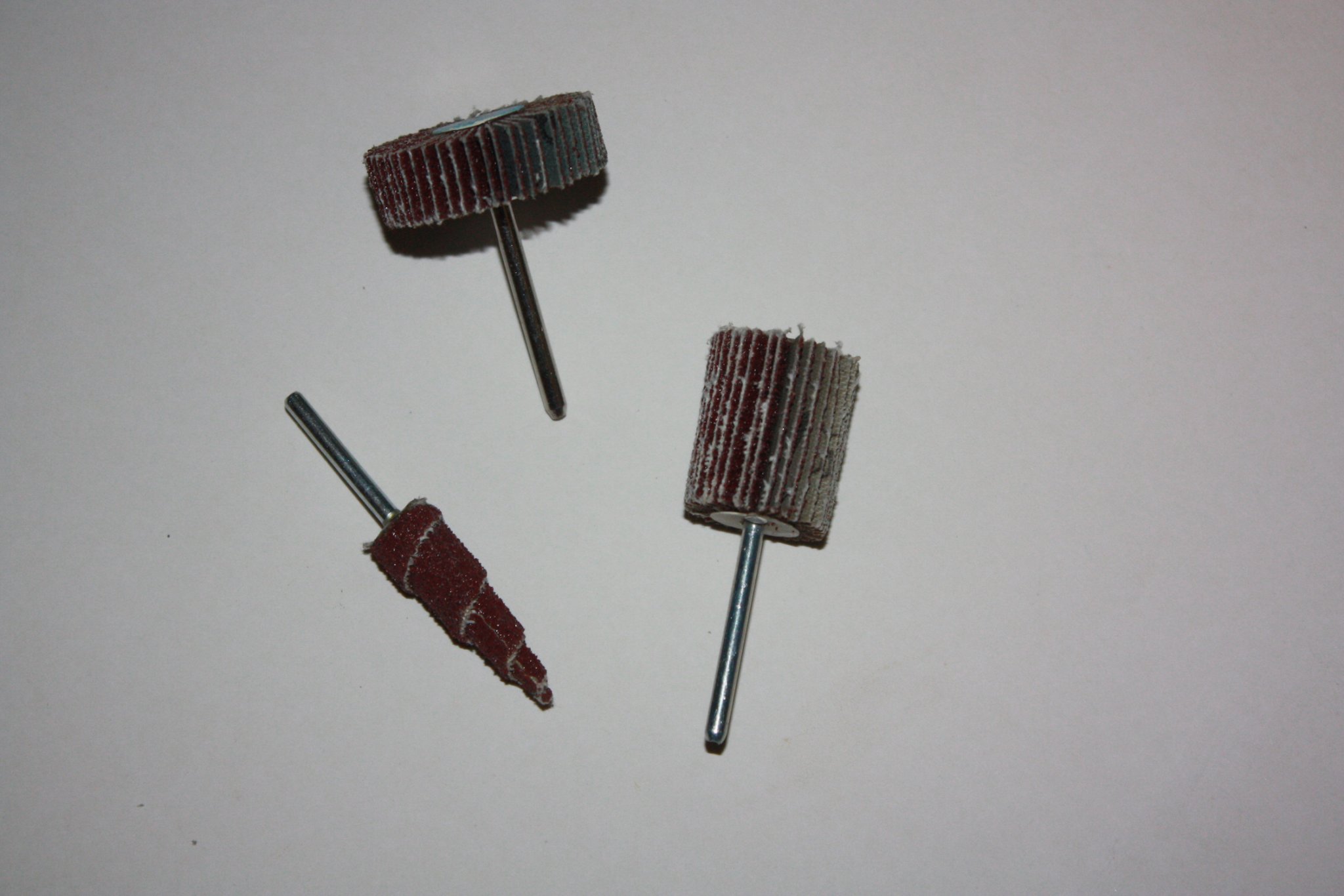
Grem I am sure there are many ways, but for me for frames or bulkheads I have found that rotary wheels do a lot of work quickly, but gentle and slow works best so as to not go too far. Light touches to get the bevel, continually checking the fairing with a flexible strip. Once close to where I want to be, I have used a sanding mouse that reaches across a number of frames, (or a couple bulkheads for OB) to be sure the bevels are fair across them. Some final hand filing or sanding is best to avoid going too far. As with most things in our hobby, especially around power equipment, WEAR EYE PROTECTION as the disks do throw off grit and saw dust. Allan

-
Ciao Rodolfo, It is nice to see such a young member join us at MSW :>) Allan
-
dolphin striker
allanyed replied to D J B's topic in Building, Framing, Planking and plating a ships hull and deck
DJ, Dolphin strikers went through an evolution of designs from 1794 when they were first introduced (at least in the British Navy) What year/nationality ship are you building? Allan -
To add sails or not? What is your preference?
allanyed replied to Bill97's topic in Masting, rigging and sails
If you are going to consider making sails I suggest you get Volume IV of The Fully Framed Model by David Antscherl. While the model in the book is at 1:48 scale, it will still have some very good pieces of information for you. That said, at the scale you are talking about, I totally agree with Chris. My opinion is that sails that are going to be out of scale will ruin the model and it will be difficult at best to make sails that are to scale at 1:96. If you look at photos of contemporary models at NMM, Preble Hall, and others museums, there are a lot of fully rigged models, but few if any with sails. These models were built by the best of the best but they did not add sails and do not look anything like a raft. (See an example below) Why they didn't add sails I have no idea, but it may be that they agreed with statements above about scale and hiding rigging. I have used high thread count (1000 or 1200 TPI) bedding material for sails on a few 1:48 scale schooner models, but only because the buyers required that the model had sails. The rigging on the schooners was sparse compared to a ship like the Cutty Sark, so the sails looked good in the end and did not really hide the rigging too much. Keep in mind these are not cheap materials. Silk Span is probably a better way to go than cloth so as to keep it closer to scale. Allan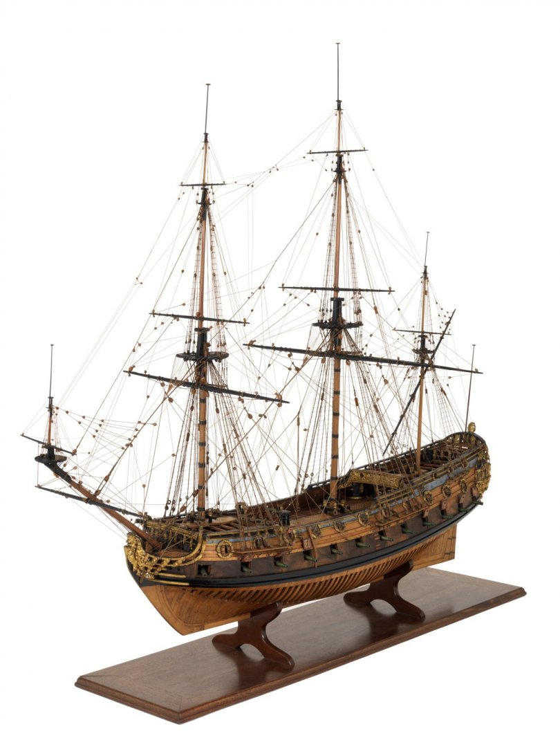
-
Barbara, Drawings of the Baltimore Clipper Badger shows wales and planking with widths of 8.5" I do not know how accurate the drawings are but can be found at www.researchgate.net I had not heard of them before nor do I know anything about them, but a quick look shows nice drawings with scantlings. I don't know where they found the original information or if it is completely accurate, but they are pretty detailed and may be worth a look. If you go to the site, just type Baltimore Clipper in the search box. Not high resolution drawings, but if you need those maybe you can contact them to get something higher resolution. Allan
-
Tom, If the pins are to proper scale, the hole will be quite small compared to the width of the rail so should not split. The handle diameter should be somewhere between 1.5" and 2" so it fits well in the hand and the lower part in the neighborhood of 1"- 1 1/8" diameter. I don't know what your model scale is but if it is the Artesania kit at 1:50, approximate hole size would be about 0.0225 (number 53 wire size drill bit) Most kits have pins the diameters of which are over sized and drilling large holes in the rail to accommodate them could cause splitting problems. If you decide to go with the kit pins and they are oversized in diameter, clamp the pin rack in a vise, mark where the holes are to be drilled and then drill the holes. A small drill press works best, but any small bench vice will do the trick if using hand drills, manual or power. Making your own pins is an option, but at these diameters, making them of wood, including boxwood, is a challenge. I have used pieces of brass rod of the appropriate handle diameter, chuck it in a drill press or Dremel type unit and with fine file, reduce the lower part to the proper diameter. Once done, the top of the handle can be hand filed to round it a bit. It can then be painted to a wood color or blackened (for ships when iron pins came into use.) Allan
-
Which direction do the tails of shrouds go?
allanyed replied to Maury S's topic in Masting, rigging and sails
Maury, There was also cutter-stay fashion used from about 1840 on, at least in Britain. Not sure if this would have also been used for a US vessel at that time.. Keep in mind that the deadeyes had much wider scores to accommodate the cutter fashion shroud throat and round seizings. If going with previous style rigging, the drawing Justin posted is from R.C. Anderson's book The Rigging of Ships in the Days of the Spritsail Topmast page 94. It is the same as given in Lees Masting and Rigging, but note the fine print, the drawing from Anderson is as viewed from outboard. For a more detailed drawing, albeit from inboard, check page 42 in Lees Masting and Rigging. Allan -
Welcome to MSW. Yes, you will not want for help here, so never hesitate to ask any questions at all. Allan
-
Panart Royal Caroline - Beware rigging plans
allanyed replied to lesser160's topic in Masting, rigging and sails
Alan, Thank you very much for the compliment, but truth is that my knowledge only goes as far knowing where to search in my small library and who to ask. My memory ain't what it used to be :>) This being only your third model, I say cudos to you. You might want to think about a scratch build on your next adventure. Part of the fun for many of us is the initial research to find a subject that is pleasing to the eye and has enough history to give it life beyond the timber used to build her. With many contemporary drawings and contracts with details, it is truly an interesting adventure. Allan -
Panart Royal Caroline - Beware rigging plans
allanyed replied to lesser160's topic in Masting, rigging and sails
Hi Alan, (Which one of us is spelling our name wrong :>)) Probably me, as people get it wrong most of the time. Anyway...… There are no lines on the cross jack that go aft. The following is paraphrased from Lees Masting and Rigging, pp 81-82. There are slings to take the weight of the yard since no jeers were carried. Up to 1773, there was , a single block was strapped to the center of the yard, the sheave running athwartships. One end of the sling rope has an eye at one end and the other end rove through this block from starboard to port, up and around the back of the mast above the crosstrees, rove through the eye on the other end of the sling and seized to itself. There should be a simple truss which was the norm until 1773 since no parrel was used. This holds the cross jack to the mast. The truss was changed after 1773 to include the truss pendent that ran down to the deck. There were also the running lifts with the running part belayed to a cleat at the foot of the mast or the bitts. The only other rigging were sometimes foot ropes with the footropes and stirrups carried directly from the yard as no jackstays were used on the cross jack. The only other rigging to the cross jack are the brace pendants and braces which ran forward as you see on your plans. Lees may be wrong or have missed something but I would trust his work before most kit instructions as his work was so well researched before being published. R.C. Anderson's Rigging of Ships In the Days of the Spritsail Topmast 1600-1720 goes into a lot of detail on the "cro'jack" and gives very similar descriptions for English ships. He gives no description on any rigging that goes aft from the crossjack on English ships. He does describe how some Dutch ships sometimes had the braces go aft. Keep in mind the crossjack was stationary with no need to raise and lower so the sling and truss were sufficient to hold it in place yet allow it to rotate around the mast via the braces. Again, I hope this information is of some help to you. Allan -
Panart Royal Caroline - Beware rigging plans
allanyed replied to lesser160's topic in Masting, rigging and sails
Hi Alan, Sorry to start off with questions, my apologies. Are you referring to the mizen yard (angled yard fore and aft yard) or the cross jack (horizontal square yard)? Do the plans show any kind of braces at all? The cross jack for the time of Royal Caroline, would have had running lifts and braces. Brace pendants were taken along the foreside of the yard and the braces would have led forward, not aft. The standing part was normally seized to the main mast shrouds, led through the cross jack pendant blocks attached to the cross jack, then forward and through blocks seized on the main mast shroud, then down to the deck. The braces cross each other going port to starboard and vice versa. There are only the truss, slings, lifts and braces on the cross jack. I don't think that the braces would be belayed to pins, but rather, to cleats at the area of the break of the QD. If you are referring to the mizen yard, which angles as a lateen, this has a totally different set of rigging as it carried a sail, unlike the cross jack. Hope this is of at least a little help. Allan -
Which Glue
allanyed replied to Old Fart's topic in Building, Framing, Planking and plating a ships hull and deck
This is a personal thing but I avoid CA. I would add epoxy for metal to wood gluing if it comes into play on your model. Allan -
Lead corrosion and lead free soldering
allanyed replied to modeller_masa's topic in Metal Work, Soldering and Metal Fittings
Many thanks for sharing this again Kurt!! I missed the earlier posts so very happy to see it come up now. Until now I would never use anything other than silver solder, but am anxious to give Star Brite a try. When you use your torch, do you just go with a softer flame than you would for silver solder? If not, I assume the danger still remains of melting the part to be soldered, which I think most of us have done on occasion. Allan -
Painting a Waterline
allanyed replied to mikiek's topic in Painting, finishing and weathering products and techniques
Grant Everyone has their own way, but I would do the colors separately. The white strip that is between the black and red it is key. I have used pinstriping tape you can get from any auto parts store or on-line. It will give a perfect line top and bottom. After it is on, the entire hull can be hit with five or six coats of clear which will soften the edge of the striping tape as it does have a slight thickness and would be noticeable on close inspection. The photo below has a relatively wide tape, but various widths are available. (The finish on the model in the photo is way to shiny IMHO, but that is what the buyer requested.) Egg shell/semi-gloss finish would probably be more appropriate. If you opt not to use tape and just go with paint, be sure to seal the masking tape that you use to give the straight edge with a couple coats of clear. It will minimize any paint bleeding under the tape. Allan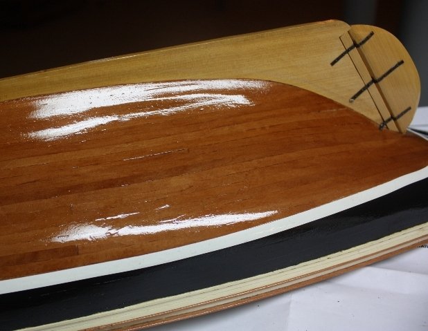
-
Tom According to Lees Masting and Rigging (page 42) the sheer pole was to prevent twisting of the shrouds and were commonly found in the 19th century. He does not say whether they were used or not earlier so it may be appropriate for Leopard. He does say that they were made of 2 inch diameter iron rod. Allan
-
I am searching for brass tube
allanyed replied to Fresh water sailor's topic in Metal Work, Soldering and Metal Fittings
I am with Phil on using MC as a source whenever possible as they are usually MUCH less expensive than a hobby shop and have a much wider selection of sizes and materials. Allan -
Problems with HMS Fly
allanyed replied to shortgrass's topic in Building, Framing, Planking and plating a ships hull and deck
Shortgrass, Hope you don't mind but I can only address the distance between decks. Assuming you are building POB, I measured from the top of the gun deck beams to the top of the QD beams at the center line in a couple places and from the top of the GD beams to the Forecastle beams at the center line. They are marked on the drawing below. These are real world dimensions so you need to adjust for the scale to which you are building. I assume you have already done so, but if not, you can open and copy a high def image of this contemporary drawing of Fly 1776 on Wikipedia https://upload.wikimedia.org/wikipedia/commons/8/84/FLY_1776_RMG_J7978.png Allan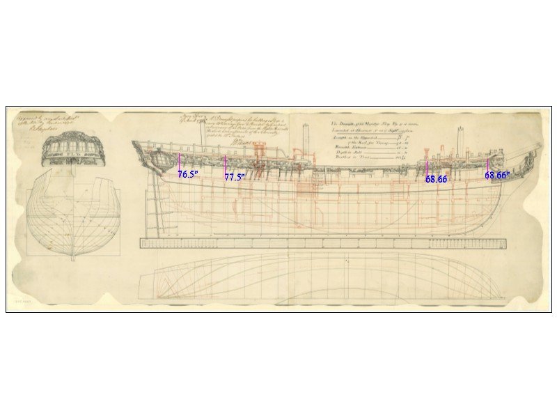
-
Hermie, What do you mean fast way is paper? Can you post a couple photos? Thanks Allan
-
Hi Michel, Sorry for leading you astray on the Young America build log . I based my suggestions on your post describing a clipper ship of Baltimore of 1840/1860 rather than a schooner of 1780-1820. It sounds like you are referring to a Baltimore Clipper which were topsail schooners that came out very late in the 18th century and were used quite a lot during the War of 1812 and well beyond. Allan
-
Bienvenue to MSW Piet de Mol. You can do a search on blocks on the rigging forum. There is a lot of information on blocks from various centuries and how to make them in the rigging forum. Allan
-
Michel, I suggest studying the excellent build log here at MSW on the Young America clipper (1853) by Ed Tosti. Truss bracket pivots were used on the yards and he gives extremely detailed explanations and photos of how to make these. Better yet, you may want to consider purchasing his books on the Young America from Seawatch Bookswhich which provide all the drawings and explanations you will probably need. While it is not the same ship, it was built during the height of the clipper era and is likely to be the best source for details on rigging a clipper. Allan
-
Caullking Planks
allanyed replied to shortgrass's topic in Building, Framing, Planking and plating a ships hull and deck
Dave, There was a lengthy discussion on caulking about a week or two ago. If you do a quick search at the top of the forum page it should come up with a LOT of choices offered. Allan