allanyed
-
Posts
8,149 -
Joined
-
Last visited
Content Type
Profiles
Forums
Gallery
Events
Everything posted by allanyed
-

Using pins
allanyed replied to Oddball's topic in Building, Framing, Planking and plating a ships hull and deck
Oddball, No questions are stupid here. Even the most experienced builders/history seekers here find something new on a continual basis that results in questions that may seem obvious to some, but not to all. Without a time machine to go back to see how it was done we all ask questions. Regarding pins, depending on the era, yes, bolts, trennals, and various other "pins" were used and many model builders make and use them, myself included. But, depending on the model scale, their inclusion can ruin an otherwise great looking planking job. Over sized trennals will make the hull or deck look like it has the measles. Say a hull is planked and "pinned" with 1.5" trennals. At 1:98 scale, these would be 0.015" diameter. The smallest hole on a Byrnes draw plate, which is a top quality piece, is 0.016 so can be done, but making nails that small is not easy, even using bamboo. Plus they will barely be visible. Where bolts are required, they can be down to 3/4" diameter which is only 0.00765 diameter at scale 1:98. EDM brass wire can be found to .001 diameter uncoated so pretty close. Go up to 1:48 and the task is easier, if not extremely tedious, when you consider there many thousands needed on a hull. Side, note --- I don't recall the model or builder, but years ago I saw photos posted somewhere of a model that used no glue at all. Everything was built as was done in the yards back in the day, with trennals and bolts. Allan -
Harve, If you taper and spile your planks correctly and pre-bend the planks to some degree you don't need any clamps or pins. Simply hold them in place with your finger for a minute or so and they will hold. This is assuming you are using pieces of plank of appropriate length, not one long strake the entire length of the hull and are using aliphatic glue. Please do read the planking tutorials here at MSW. Allan
-
Lots of great advice above. You may want to also consider the thickness of the wood and the type. Many kits seem to use walnut that is very thin and grain is also an issue so splitting is not uncommon compared to other species. Dry bending is OK for many species, but not all. Allan
-
Thin hull planking
allanyed replied to Gerarddm's topic in Building, Framing, Planking and plating a ships hull and deck
The type of wood can make all the difference. Walnut is not a good choice as it is so grainy and thin pieces tend to crack and split with ease. Take a look at the "Wood Discussion" section here at MSW and you will get an idea of what woods are being commonly used with success. Some are reasonably price, some are dear. As to thickness variations if you are ripping your own, Barkeater has a great point. A thickness sander is a great way to get even thickness but that is an investment that you may not want to make at this point. Even if they are varying in thickness, once in place on the hull, you will be sanding anyway and this should take out any variations in thickness. Allan -
Hi Jeff, One more comment. Tim's photo is really great.... except..... there looks to be a bottle of CA glue. UGH! (My own personal opinion and certainly not a universal one😕) If you can start your endeavors into wooden ship building without it, I think many, if not most, members here will agree that you will be better off. There is no need for CA anywhere in building wooden ships and based on posts here at MSW it seems it causes as many problems as it solves. I think by now you see what I meant about getting input from the crew. Allan
-
Hello Jeff, I did a quick search and found a couple videos that sound like the ones to which you are referring. (DevMa models?) My apologies to the builder in the video, but IMHO I would not use anything from the planking video as a how-to guide, including his use of pins. First and foremost, study the tutorials on planking here at MSW. Follow some other builds plank-on-bulkhead models like similar to your Albatross. There are numerous posts here at MSW on what tools are needed/recommended and these are a great reference. For the kit, I would guess hand tools will suffice, so no big investment is needed to start off. Specifically, regarding pins, Tee pins to temporarily hold the planks are an option, but definitely not pins shoved all the way home as they need to be taken out. Remember that the magnificent contemporary models from hundreds of years ago that still exist today were built with hand tools. First time builds can launch you into a lifetime of builds or end the journey with the first model. You are very lucky to have this forum available to you as most of us had no such source of thousands of helpers and teachers when we started our first builds, so take advantage of it and learn from our mistakes. Most of all, have fun with your project!!! Allan
-
Thanks to each and everyone of you. Room in the shop is not a problem, but in the house for display, it could be. 1:72 is definitely out. Thanks again and Happy New Year. Allan
-
I hope to start construction of Litchfield (50) 1695 this coming year. Her gundeck is 150 feet. Over all length, rigged she is about 200 feet thus about 50" at 1:48, 37" at 1:64 and 33" for 1:72. I am still wavering on scale, be it 1:48 or 1:64 or 1:72 . As I hope to fully rig her and show good detail, I am leaning to 1:64 (or possibly 1:72) but nothing smaller after discussions with Ed T. I really want to be able to get the detail, yet not have a monster to display but 1:72 worries me. Old eyes and all that need to be considered. I am looking for any advice from anyone that cares to share, based on successful or not so successful experience. Thanks to all Allan
-
Gary, Your shop is larger than our first apartment!!! Good for you on your retirement, super congratulations. Allan
-
If you can live with what appears to be a close substitute, you may want to consider Buxus macowanii, aka Cape Box, from Rare Woods USA. Allan
-
Kapas The dimensions appear to match closely to Sutherland's Shipbuilding Unveiled for a 225 Ton vessel. I saved the image from Gregory above, inserted into a cad drawing, scaled it to the scale laid on the drawing that Gregory posted, then saved as a PDF and printed. Came out dead on and is 76.2 mm (3 inches). If you still need a drawing, please feel free to PM me your email address and I can email you the PDF which you can use to print the sheet on your home printer. Allan
-
Castos, With the equipment you show, you hit home for me. I have similar a situation and have not had a proper work area since we moved south several years ago. We have gone to one car so there is now room in the garage and your layout looks similar to what I have in mind. My only problem is that the summers in SW Florida can be stifling, so at least a ceiling fan and/or a portable AC unit or some such will be part of the set up. Any suggestions here would be more than welcome. I am seriously considering setting up a bit of duct work and large vacuum system or adding a semi permanent shop vac as it only needs to be used when making sawdust anyhow. Would be nice though to enclose it to cut down the noise. Any suggestions on this would be welcome as well. Allan
-
How many riders?
allanyed replied to Bluto 1790's topic in Building, Framing, Planking and plating a ships hull and deck
The following is a higher resolution IB Profile of Vanguard 1748 that shows the floor and futtock riders more clearly. You can save it and enlarge quite a bit. This is from the earlier post on NMM hi res drawings on Wiki. Hope it helps. Allan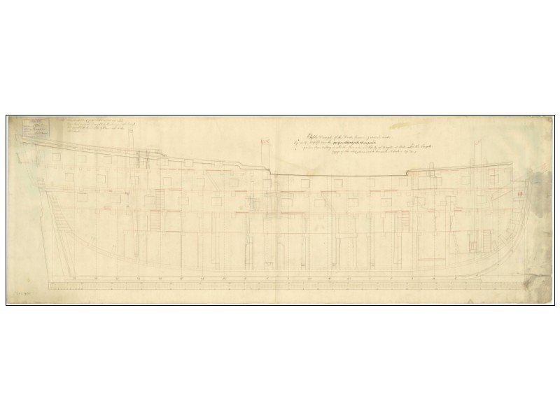
-
How many riders?
allanyed replied to Bluto 1790's topic in Building, Framing, Planking and plating a ships hull and deck
Jim The Shipbuilder's Repository (1788) does not give the number of riders for a 50, but does give three for a 64. The 1770 inboard profile drawing of the Portland class 50s, which includes Portland, Leopard, Jupiter, Adamant, Leander and Europa shows three and their locations. https://collections.rmg.co.uk/collections/objects/81511.html Allan -
Thanks for posting Druxey, I hope there will be more information coming from them even if they have no plans to recover the remaining 75%
- 1 reply
-
- 4
-

-
Hi Colin, As Peter said above 30,000 heads are better than one. You may actually wind up with too much information on occasion when asking questions here but that is a good thing. I have learned more from questions asked by others at MSW than those I have asked on my own. It is win-win for all 30K of us when you or any of us run into a roadblock and need a bit of help. Welcome!!!
-
Tabled Clamps
allanyed replied to allanyed's topic in Building, Framing, Planking and plating a ships hull and deck
I think we have a consensus! Thanks Druxey. I don't know that I look forward to actually making these, but it will be an interesting mini project to be sure. Allan -
Hi Mike, You will get all the encouragement in the world here and great advice as well. Welcome to the team, you just picked up thousands of new friends, and advisors!! Allan
-
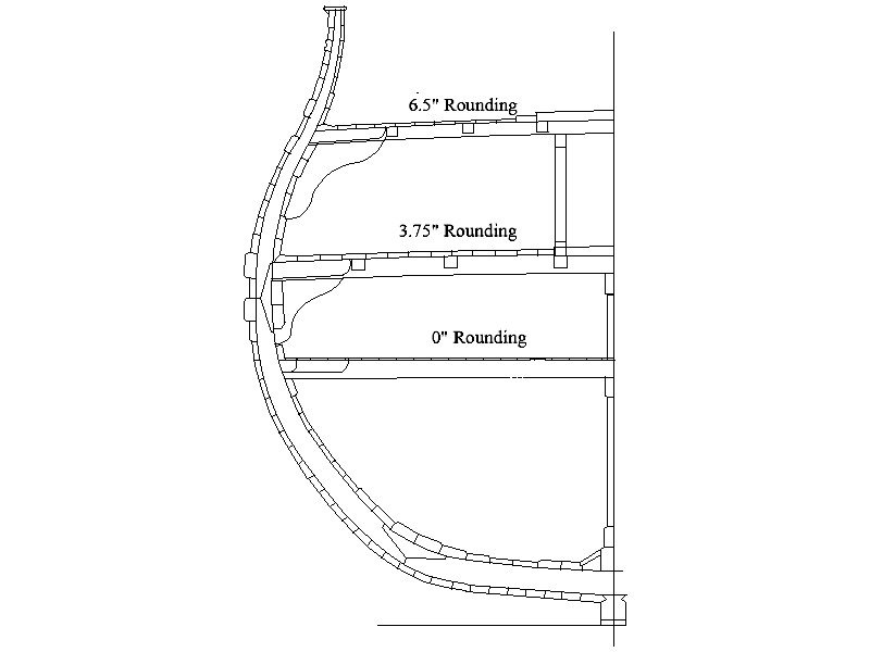
I am not sure what you mean by skyward. Decks generally had deck beams with rounding of various amounts although the Orlop often did not. The below is from a fourth rate of the late 17th century. When you describe skyward I was thinking it to be concave, not convex which I don't think would be correct on any ship of any era. Allan
-
Sergeant Tom ( I assume this is the source of your screen name as you served as a marine) There is a mention of nails to hold wet planks in place above. Planks will swell when wet so do not try to glue wet planks in place as they will shrink when drying and leave a slight gap between strakes. You can pin the wet planks in place without glue then remove them when dry and then glue the dry formed pieces in place. I will not go into spiling as I understand most if not all the kits only include strips for the planking and you will be relegated to using these and the included issues with bending in two axes. If you do use pins there are going to be holes that can be seen so consider using the pins in the spots where you would use treenails after the planks are glued in place. As also mentioned above, there are a variety of planking clamp ideas here that you may wish to try. Just be attentive to clamping wet wood as you could leave dents in the planks made by the clamps. Regarding CA glue, based on having used it in the past, my personal opinion is there is no need for it in ship modeling. PVA for wood, silver solder for metal work, epoxy when needed, and diluted white glue in rigging when called for. Please do consider posting a build log as you will get a lot of great advice as you progress. Allan
-
Tabled Clamps
allanyed replied to allanyed's topic in Building, Framing, Planking and plating a ships hull and deck
After further discussions directly with another astute member here, another possible solution has been raised. The verbiage in the contract describes the clamps and spirketting of two strakes to be "Tabled in the meeting edges AND scarphed hook and butt" Taken literally this could be that there are two parts of the construction in play. The following sketch is what was proposed as a possible design based on the worded description. Allan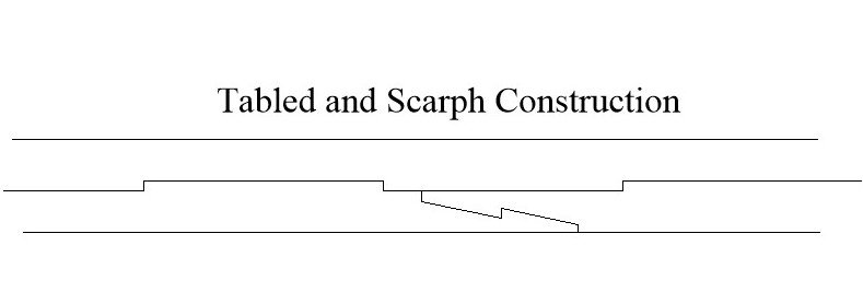
-
Chocks for futtocks
allanyed replied to allanyed's topic in Building, Framing, Planking and plating a ships hull and deck
Bob and Alex, I have gone to Batchvarov's thesis a number of times over the past few years and I thank you for bringing it up as it is a great source. He describes the use of chocks that cross the keel as well as chocks where the futtocks join in Chapter 3 of his thesis, Framing of Ships in the Second half of the 17th Century including a sketch showing shouldered chocks on page 51. He has several charts showing a number of vessels with information from contemporary sources, including contracts, that indicate the use of scarphs on some and chocks on others. I have just recently emailed Karoum to discuss this very topic but no luck so far in getting a response. Jaager, I appreciate your response and sentiment. I have not really researched ships of other nations on this project but in sketch C in my earlier post it shows a chocked joint found on a Swedish ship wreck frame. I have no idea on their use in other nations. Whether they show on the model or not, they do add strength to the framing and for me, these details are part of the fun in construction. I would not encourage nor discourage the use of such details to others, it's just my own personal preference to include many details even knowing no one will ever see them or that they would even care if they did 😆 Allan -
Chocks for futtocks
allanyed replied to allanyed's topic in Building, Framing, Planking and plating a ships hull and deck
Thanks!! I do hope there are some photos or drawings to be found from wrecks of the late 17th century. And the search goes on...… and on...… and on....😁 Allan -
Tabled Clamps
allanyed replied to allanyed's topic in Building, Framing, Planking and plating a ships hull and deck
THANK YOU DRUXEY!! -
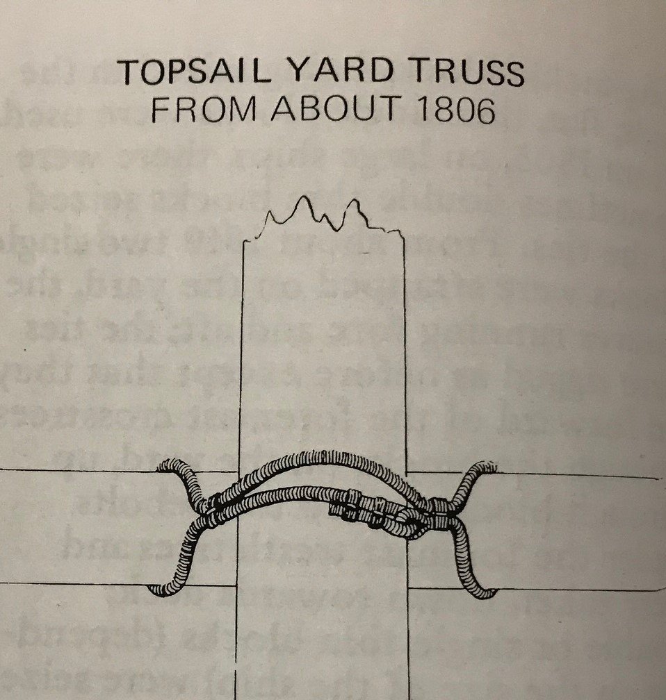
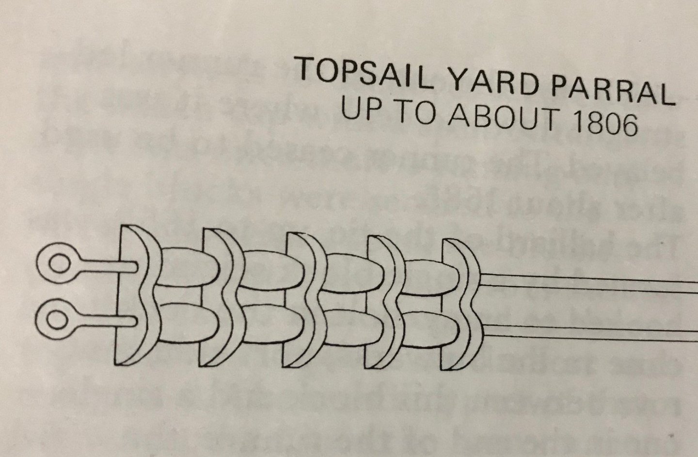
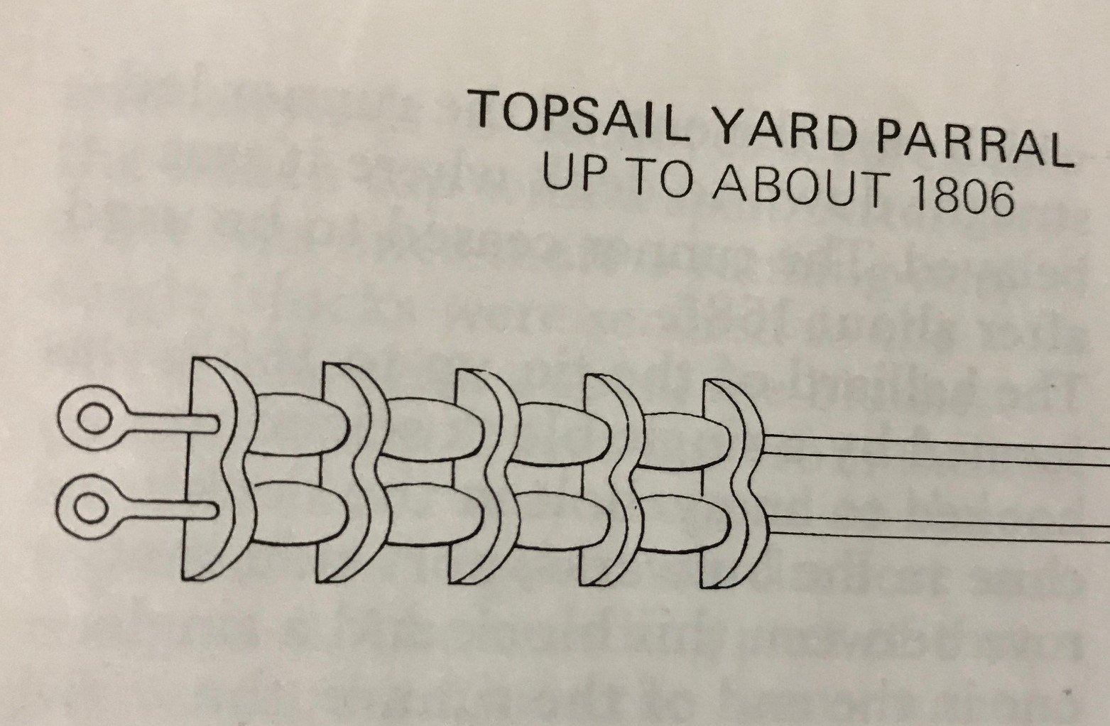
As Henry said, you need something to allow the yards to be moved, be it a parrel with trucks and ribs or a truss parrel, which was made of rope with no ribs or trucks (beads) The following pictures are from Lees' Masting and Rigging page 84. Allan