HOLIDAY DONATION DRIVE - SUPPORT MSW - DO YOUR PART TO KEEP THIS GREAT FORUM GOING! (89 donations so far out of 49,000 members - C'mon guys!)
×


allanyed
-
Posts
8,149 -
Joined
-
Last visited
Content Type
Profiles
Forums
Gallery
Events
Everything posted by allanyed
-

Endeavour Longboat
allanyed replied to Rick01's topic in Building, Framing, Planking and plating a ships hull and deck
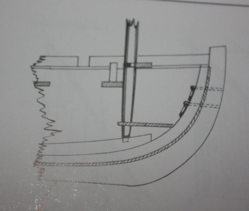
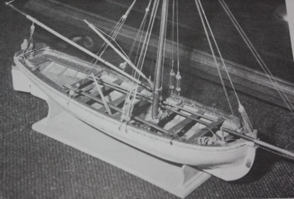
Rick, I apologize if this comes out badly, but there seems to be a couple mistakes in this kit designed boat from what I can see in the photo. There would not be belaying pins as shown, but rather thole pins to keep the oars from sliding forward or aft or space between splash boards' supports. Also, if the boat was single banked (one rower per thwart), the thole pins would not be directly across from each other port and starboard but would alternate for thwart to thwart. If it was double banked (two rowers sitting side by side on a single thwart) there would be thole pins on each side in line with each. Double banked boats were the largest and usually found on much larger ships than the Endeavor. My guess is that it was a single banked boat. Most long boats used one mast, although some did have more than one. I have some doubts that there would be two on a long boat for Endeavor but have no hard evidence to the contrary. There are no frames showing in the model. They would be pretty much exposed. The stem is much to high. The planking does not look at all right. The mast would taper as shown on the attached as well as towards the top. I suspect all the other spars/sprit, etc. would taper as well, but I may be wrong and some one else can confirm or correct. The attached are from Lavery's Arming and Fitting 1600-1815 Allan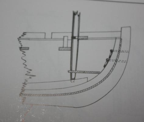
-
Tony, I spoke with Bob and he does not have any spare disks, they are all wrapped in the books so he agreed I should make a copy from the originals and send your way. I am traveling and out of reach of my files but will burn a copy of the frame drawings on a disk and send your way when I return next week. Please send me your address via PM. Hope this is at least a little good news. Allan
-
Tony, I will ask Bob at Seawatch the status. Allan
-
I think adding the bolt rope to the model sails should be done, if only to keep the sails from fraying, especially where the mast hoops are tied to the sail. Allan
-
Danny, You know the quality is top shelf when you can show those close ups and there are only flawless pieces of workmanship to be seen. Well done and thanks for being willing to show those close up shots. They are very helpful. Allan
-
The devil is in the details. Your tank is a great project in itself, and those are the kinds of details that separate the best from the rest! Allan
- 3,618 replies
-
- 1
-

-
- young america
- clipper
- (and 1 more)
-
I had the privilege to preview this book and see the model while under construction and I can say that it is a must for any scratch builder or kit basher. There are a lot of new areas covered that are not to be found in the TFFM series such as an extremely detaled description on building the galleries, not to mention the design and construction of a ship with the specific purpose of being a fire ship. I was supposed to be proof reading for errors but I became totally engrossed in the text and illustrations and enjoyed the read as much as I found an appreciation for its usefulness to the model builder. Allan
-
I have Petersson and TFFM and they are super, especially TFFM. My fall back is James Lees' Masting and Rigging as he addresses lines, line sizes, blocks, the works, for any size British Warship between 1625 and 1860. Allan
-
Chris, For length of a hull plank, any length between 25 and 30 feet long would be realistic. The width will vary along the length of each strake. The deck planks will vary as well as in both cases, the ends must land on a frame or beam. In addition, the outer strakes of deck planks in naval vessels often were anchor stock or other variation rather than straight pieces for added strength. A hull will have a number of different thicknesses between the keel and rails. Each deck will have a different plank thickesses as well, plus different dimensions for binding strakes if used. What ship, size, year, etc. are you working on. Allan
-
Keel taper
allanyed replied to Redshirt's topic in Building, Framing, Planking and plating a ships hull and deck
Daniel, I don't know if they are appropriate to the Eagle, but the scantlings in the 1719 Establishment, the 1788 Shipbuilder's Respository and David Steeles Elements of Naval Architecture all include the sided dimensions of the keel afore, midship and aft. As Druxey mentions above, none of them indicate where the taper begins, and I agree with the assumption that it begins at the cant frames, but it is obvious from these dimensions, there definitely is a reduction in siding. Allan -
Jeff Are you sure the standing rigging for the Wasa was tarred? If it was, would it be more of a dark brown versus black? Maybe the kit is accurate historically in providing tan line. I don't know, just a thought. Allan
-
Tim, What ship and year do you have in mind? Bulkheads were not always moveable or removeable. They are describe in a contract of 1666 with no suggestion that they should be removeable, (from Deanes Doctrine page 118 and quoted in Lavery's Arming and Fitting page 172.) Lavery also goes on to state that the bulkheads became lighter and more mobile during the 18th century but even so the captain's cabins on late eighteenth century frigates were permitted some semi permanent bulkheads. By an order of 1779, there were to have "one firm bulkhead at the fore part of the captain's apartments and fixed between two guns so as to admit of their being worked in case of a surprise in the night. The after bulkhead to be of canvas, and fixed as the captain shall desire." Allan
-
Richard The index in volume two is several pages long so I will not detail it here, but basically Vol II continues the construction of the hull through completion. Volume III is basically a series of photos of Greg Herbert's build (Well worth having) and IV is masting and rigging. Allan
-
Jeff, is the strop on the real block "buried" in the block or on the outside? I have built blocks for buried stropping in layers and if they are really tiny, I have drilled holes to bury the wire versus using a strap, leaving enough out to for an eye. These have been for schooners from 100 years ago. I do not know if this would be appropriate for the J boats, even the oldest ones. Is the following the type you need to make? Allan
-
Al, If this was already mentioned above, my apologies, but I did not see it and was surprised it was not mentioned. Not for now, as it is too late unless you want to start over, but for your next challenge, the lower strakes of hull planking should not run so far forward. The planking tutorials as mentioned above are worth their weight in gold so definitely study them. Welcome to the world of ship model building, also known as the angst society. Allan
-
Ciao Mauro I like your model very much. The rigging looks very good, including the beautiful knots for the ratlines on the shrouds. I have one question, I hope you don't mind. There is the main sheet block rigged to the horse on the transom, but there is also another block rigged to the same horse. What is the second line? Again, very well done model, thank you for sharing. Allan
-
Ed, I like that you showed the photo of how you fit the ledge. As you have shown, I also field fit each ledge as well as the carlings at times. As close as one can be to the plans in their build, there is always the need to field fit some items and the model builder should not feel they have made a mistake by having to do so. There is not doubt that the full scale ship yards measured and cut in the field at times just as you have shown in your scaled shipyard. Showing these little things in your log is huge.. Kudos Allan
- 3,618 replies
-
- 1
-
-
- young america
- clipper
- (and 1 more)
-
CA glue question
allanyed replied to MikeB4's topic in Building, Framing, Planking and plating a ships hull and deck
jud Say you have a 30 foot long plank, thus about 14 frames on a fully framed model. I used to use aliphatic glue on all but two or three frames. On those couple, I would use gel CA to get an almost instant bound to hold the plank in place. I have since quit CA altogether as I hate the fumes and use aliphatic and clamps as needed to hold the part in place until the glue cures. Allan -
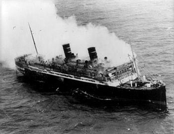
Today is the anniversary of the fire on the Morro Castle. Some of the crew abandonded ship and there were lifeboats launched with many spaces available. There is a theory the Captain was murdered and the fire intentionally set. Allan
-
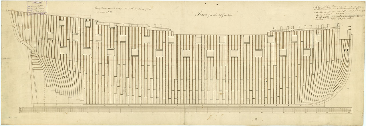
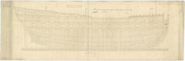
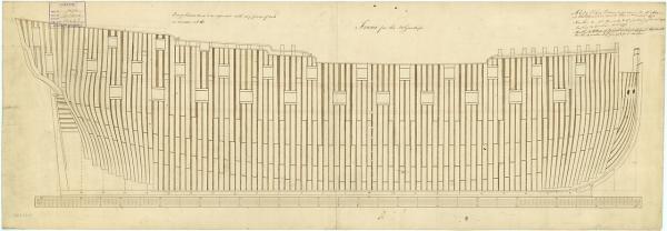
Thank you very much Wayne, I had not seen those and appreciate you posting. Alas, I am looking for drawings with cant framing in the disposition drawing and a bit more detail.. The drawings I am used to seeing show offsets and canting of the various futtocks around gun ports, sweep ports, etc. Sutherland is pretty basic, not unlike the majority of framing on the contemporary dockyard models. I wonder if the Sutherland drawing is supposed to be more suggestive than actual. Some of the gun ports do not meet the framing on both sides and others show half the siding of a frame cut away to allow the gun port in place. Two examples of dispostion drawings from the National Maritime Museum Collections website are attached, a 74 from 1763, and a 50, the drawing of which is from 1776. Sorry to be so picky. I really do appreciate your taking the time to post your response. Allan
-
Rob, If you find a framing disposition plan earlier than about 1760 please let us know. I have been researching like crazy circa 1719-1745 and have found none. The only thing remotely close is the fully framed model from 1715-1717 that shows all square frames on one side, and use of cant frames on the other side. Franklin has a lot of photos of this model in his book and the NMM site has several. http://collections.rmg.co.uk/collections/objects/66366.html Allan
-
Nenad, I have the magnifier on more than off these days. Silver soldering and drilling and bolting 2 mm is not bad so bad. 1mm, now that is getting more difficult! You can make bolts with 0.010 brass wire which is 1/2" at 1:48. Even with 1mm, there is plenty of room for this size "bolt". Allan
-
J If you want the rudder to be able to move, you will need to make working "hinges" The rudder can be completed first then the hull straps with the gudgeons temporarily tacked to the pintles on the rudder and then held to the hull to mark hull strap locations. I would not use glue as you will be gluing to the varnish, not the wood. Or, scrape off the paint and varnish to expose the wood. I prefer to "bolt" the straps with tiny brads. Allan
-
Danny I like the varying vee block set up. Are there just the two we see in the photo or do you have more to support longer pieces so they do not bend during the chiseling process? I am very happy to see you demonstrate that a sharp chisel can do wonders, and dowels are not necessary to make masts or spares. Allan
-
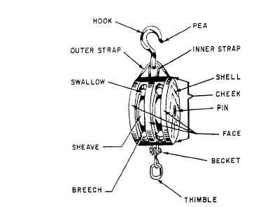
Lees gives similar dimensions. Pick your medicine Common single block Width of the sheave was 1/10 more than the diameter of the rope, the diameter of the sheave was four times the width of the sheave. The width of the sheave hole was one sixteenth more than the width of the sheave and the length of the sheave hole was one and one third the diameter of the sheave. The length of the shell was eight times the width of the sheave hole; the width was two fifths the length of the shell; the breadth was six times the width of the sheave; and the position of the pin was eleven twenty- firsts from the top of the block. The edges of the sheave hole were chamfered off and the shell slightly rounded. The pin was made of wood on small blocks and iron or brass on larger blocks. For common double or triple blocks they were made in the same proportions as the single blocks except in the width of the shell. This was increased by the separating piece or pieces between the sheaves which were five sixths the width of the sheaves. James Lees; The Masting and Rigging of English Ships of War page 164 Allan