allanyed
-
Posts
8,149 -
Joined
-
Last visited
Content Type
Profiles
Forums
Gallery
Events
Everything posted by allanyed
-
Steven Those sails are gorgeous Allan
-
The really may be worth a try as the ink will bleed through giving a mirror image. LOTS of ink going to be used though and it might require a double pass which is what I have done on flags on silk span.
-
You are of course right Ron. What I do to get a light color on a dark background is use light grey or thistle in TCW. Not a pure white for sure, but maybe an option. Allan

-
If you use silk span for the sails you can make a drawing of the symbols with any CAD program including something as simple as Paint so you can then print the symbols onto the sail material. You will need to do a mirror image as well to have it show on both sides. Silkspan is easy to pre-paint the red you show before doing the symbols. Print before cutting to shape. If the sail is larger (8.5X11??) than what your own printer can handle it may be best to take the sails to a print shop along with a flash drive that has your drawing on it for them to do the printing. There are a number of posts here at MSW on using silk span as well as super information in on sail making in a little booklet by David Antscherl available from SeaWatch books for $5. Hopefully other members will have some alternate ideas that will be more helpful. Allan
-
 Very neat work Aydingocer. One thing that looks off and it may be the photo but the blocks in the last photo appear to be upside down so the line would rub against the inside of the shell rather than around the sheave. If they are upside down it would be pretty easy to drill the second hole as in the second photo below and would look as found on real blocks anyway. Allan
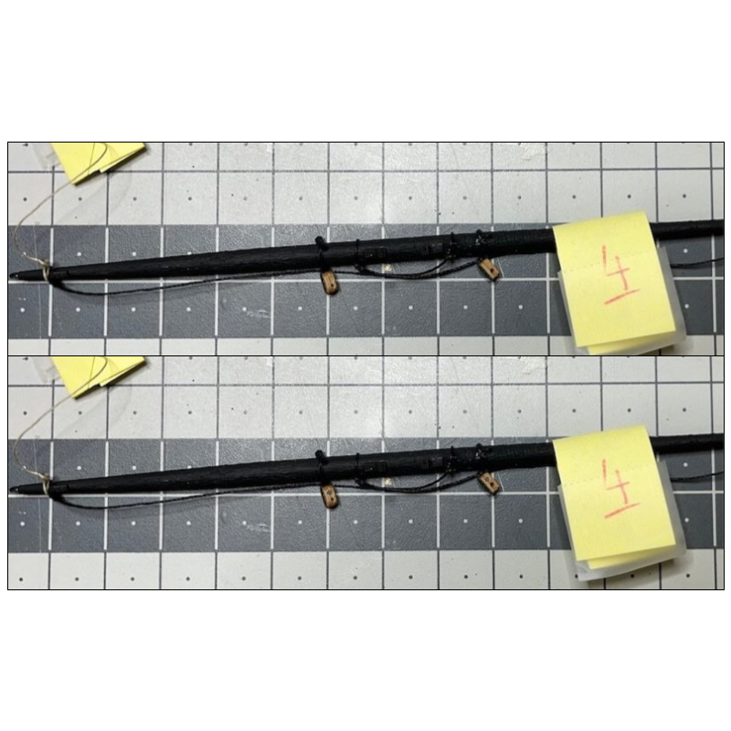
-
Love the ship's boats, especially that you appropriately showed both single banked and double banked construction. Too often instructions incorrectly call for double banked design even on the small boats. Allan
- 302 replies
-
- 1
-

-
- Diana
- Caldercraft
- (and 1 more)
-
How to measure masts for Sovereign of the Seas
allanyed replied to Andy Whincup's topic in Masting, rigging and sails
Welcome to MSW Andy. Do post a little intro about yourself in the new member forum here at MSW If you are measuring for the SoS of 1637 From 1627 to 1640, according to David Lees, Masting and Rigging, page 183 Main mast length = Beam X 2.4 46.5 X 2.4 = 111.6 feet. It was measured from the heel where it enters the step that rests across the keel. The foremast length is the length of the main mast times 0.8 111.6 X 0.8 = 89.28 feet At scale 1:78 the main mast is nearly 12 " above the upper deck. There should be plenty of room for the top (crow nest) The largest diameter of each mast for this time period would be 1 inch for every 3 feet of length. There are a lot of contemporary drawings and paintings of SoS at RMG that may be of interest to you. https://www.rmg.co.uk/collections/search/Sovereign of the Seas 1637 Allan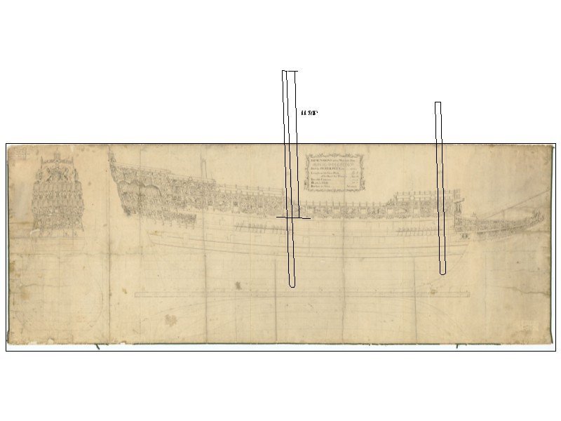
-
That sentence would work well in the Them Old Jokes forum here at MSW. I think I speak for all who have tuned in, to use an old maritime phrase, we have every confidence you will finish with flying colors. Allan
-
Spectacular rope work Dave. The seizings are beautifully done and add a lot to the overall work. KUDOS! Allan
-
The construction paper I have is 0.007" thick so would be about a half inch seam which would be OK, but you may find the appearance to be a little too thick. If you can. experiment with both to see which looks best to you. After you make your planks to the breadth and thickness that you want, glue a few planks on edge on the sheet of paper and let it dry. I usually lay down several strips on edge at a time with a little space between. (You will only need to glue the paper on one edge.) Once the glue is cured use a scalpel or other sharp razor cutter and cut the strips apart then shave off the excess. Just be careful not to gouge the edge of the wood of the plank. Allan
-
Jorge, What scale are you working on? If you are not happy with a pencil or marker, black tissue paper that you can find in most any craft store works very well for smaller scales. There is no seepage so the line is constant. It is visible but subtle. If you are working at 1:48 or larger black construction paper works very well. Both can be glued with white or yellow PVA or even matte medium. PVA (wood) glue for wood to plastic does not work well. If you do go with the plastic, epoxy or polyurethane glue should work well. I am guessing trimming plastic would be difficult. If you are working very small scales 1:96 or so it may be better not to use anything as it could look overdone. Allan
-
For the future you might want to check out the string of posts in https://modelshipworld.com/topic/34577-taper-of-the-keel-stem-knee-of-the-head-and-stern-post/#comment-985522 Some find it of some importance, others not so much. Allan
- 129 replies
-
- 4
-
-
- Victory Models
- Pegasus
- (and 2 more)
-
Thank you Craig, This study has been a fun topic for me, and I hope for those that have tuned in as well Allan
-
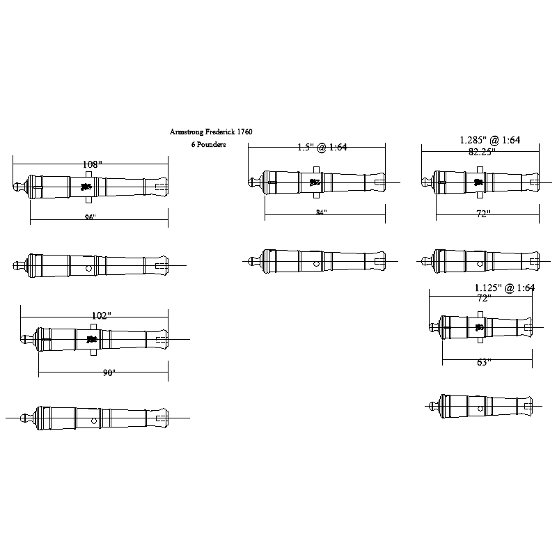
Sorry for the late reply. If you have not already gotten the information that you need do you know what the designated length or actual length of the 6 pounders were in full size? I can send you the appropriate drawings and dimensions at your scale of the Armstrong Frederick pattern in a high resolution, but in the meantime, the below may help. The designated length was usually as measured from the breech ring to the muzzle, but for these small vessels, they were sometime shorter than the common length. See David Antscherl's TFFM Volume II page 129. Also, from The History of English Sea Ordnance, Volume II by Caruana, page 217, while lengths were generally expressed in whole feet and half feet, in reality the actual variation was as much as plus/minus 2 inches (or for 1:64, +/- 0.03" (+/-0.8mm)) There are a number of sources for turned and cast barrels, but I have had very high quality barrels printed in black resin, including the cypher and trunnions for well under $1US each including postage. Allan
- 129 replies
-
- 8
-
-

-
- Victory Models
- Pegasus
- (and 2 more)
-
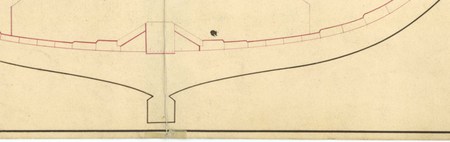
Hi Darius I have found that the four books you show are some of the most useful to be had. One comment, hope you don't mind. The strakes near the keelson would normally be about a foot away from the keelson. There would be limber boards between the keelson and the first limber strake which is rabbeted to accept the limber boards. From both Steel's Elements and Practice of Naval Architecture 1805 and The Shipbuilder's Repository 1788 the limber boards were small pieces not to exceed three feet long and on a first rate were 3.5" thick. They typically had two holes in which fingers could grab hold to lift them. They rested as shown in the drawing below without fastenings. On a 100 gun ship the first limber strake was 8 inches thick and 15" broad. The second strake was 6 inches thick and 14 inches broad. Allan
- 25 replies
-
- 1
-
-
- Victory
- Cross-Section
- (and 1 more)
-
Thanks Craig. While this is a bit later than the era I am working on for now, it is very informative. I see sandwiched trucks at this point in time as well. Regarding the straps, most models don't show these and at our common scales, probably not worth the extra work as they will be barely noticeable at the most. For larger scales such as 1:24 or larger, they could be a nice added touch. Allan
-
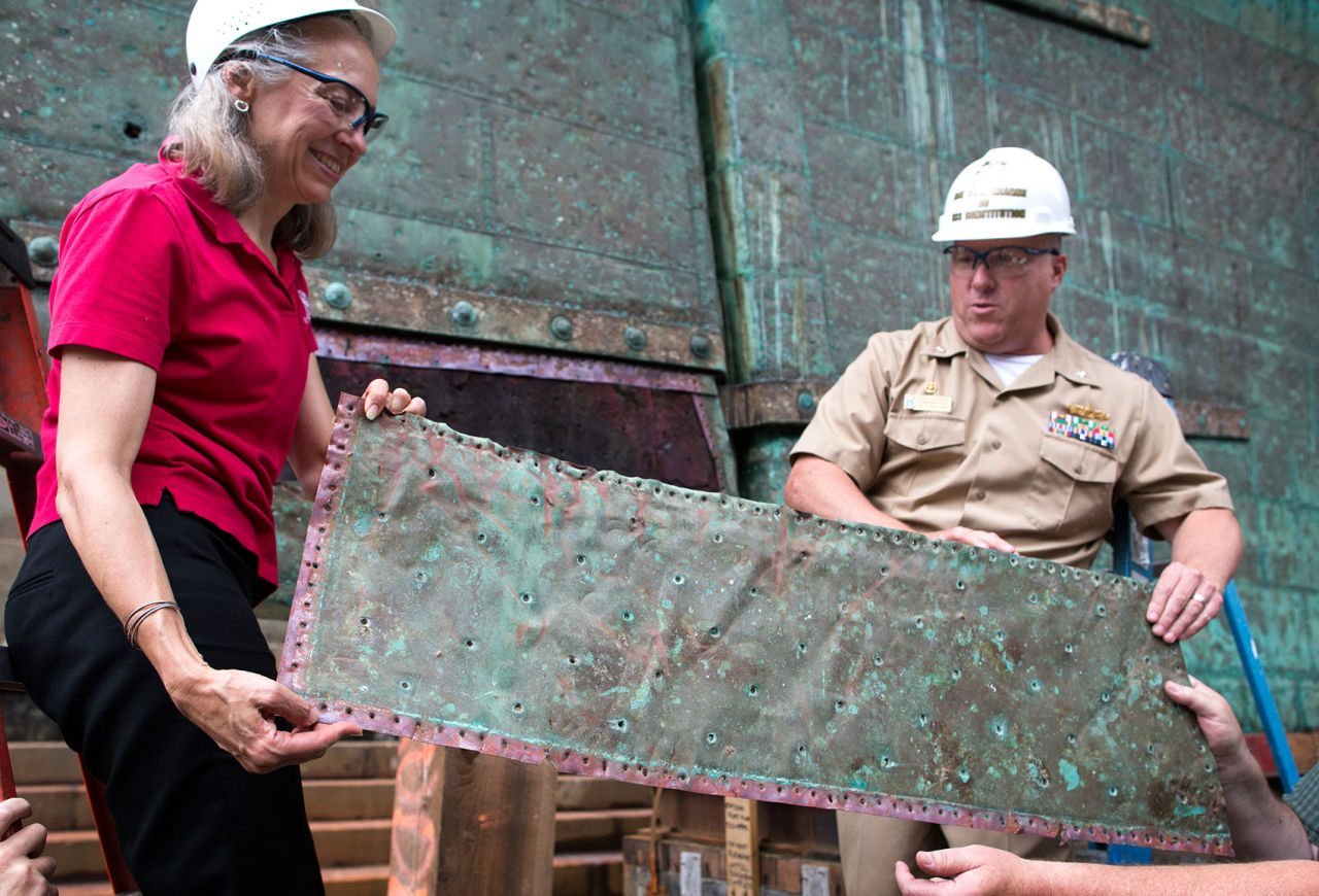
Picture of USS Constitution copper plate says it all regarding color. I realize many folks won't like the look of weathered copper, but it is another choice. Note the number and size of the nail holes rather than the over scale rivet-like bumps seen on some model plating. Can the plates with bumps be reversed so as to look more realistic with nail dents versus the look of rivets which were never used? Some manufacturers have gone to laser marks that etch small dents so there are no bumps and look much more realistic. Allan
-
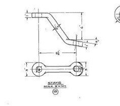
Thanks Pat and Craig. You Melbourne guys are tops in my book! Allan This is what I would have gone with had I need seen the drawings above. Do you have a source that shows the rectangular stay rather than the US version? The rectangular version would have been much easier to make full size, but if there was to be a rabbet cut into the axletree, the reduced arm width on that found on the Constitution would use a smaller cut into the axletree and thus less weakening. Thanks again! Allan
-
A very warm welcome to MSW Ian. Enjoy the ride!!! Allan
-
Even 40 plus years in this hobby does not alleviate the opportunity for me to learn. Seems I find new and useful information on this site nearly every day. Allan
-
Love the J Class and I am anxious to follow your build to see how the kit is outfitted. Looking good so far😀 Allan
-
This is a really interesting method using bulkheads in large numbers instead of few bulkheads then filler blocks. Almost a cross between POF and POB, a really great idea!! Allan
-
I just received some additional information from Chris Watton who was kind enough to send me the following references which cover from 1720 into the 19th century. He let me know that AOS books on the Alert, Blandford, Victory and Pandora and Alan McGowan's 'HMS Victory, her construction, career and restoration, show carriage details. I looked at a couple of these that I happened to have and noted that Blandford 1720, which would likely have carried Borgard pattern guns when launched, shows no straps on the carriage drawings. She may have been re-outfitted after 1724 with Armstrong pattern guns and different style carriages but I am not sure when the use of the straps was introduced. Allan
-
Bob/Lucy Have you looked at any planking expansion drawings? The strakes widen at the stern towards the keel and in the following cases they narrow closer to the wales. https://www.rmg.co.uk/collections/objects/rmgc-object-83709 and https://www.rmg.co.uk/collections/objects/rmgc-object-83495 show two examples. They show outboard planking as well as inboard planking. Allan
-
Thank you Pat. Can you post or PM me a higher res version or maybe give the dimensions on the stay as I cannot make them out when downloading and enlarging. Looking at the lower drawing, it appears that the strap is going into a rabbet in the axletree rather than having a rounded bottom. After seeing these various drawings, it is likely another case of multiple solutions to the same problem, none being wrong. I never realized the American long gun is very similar in appearance to the Armstrong patterns right down to the button ring. The top plan looks like an Armstrong pattern where as the lower looks more like the Armstrong-Frederick pattern. Live and learn! THANKS AGAIN Allan