


allanyed
-
Posts
8,065 -
Joined
-
Last visited
Content Type
Profiles
Forums
Gallery
Events
Posts posted by allanyed
-
-
28 minutes ago, DaveBaxt said:
First off ,Would this tool work on cotton thread
HI Dave,
Cotton does not melt, but dry cotton will burn at about 420 degrees F. (232.22C). Once lit, cotton thread can act like a fuse and continue to burn. Cotton will ignite spontaneously at about 760F. Other sealing methods that you mention have been discussed ad infinitum and each method has its fans and detractors. Whatever you find works best for you is the way to go.
Allan
- Canute, mtaylor and thibaultron
-
 3
3
-
Anything from Chuck Passaro or David Antscherl's three craft series.
https://modelexpo-online.com/Model-Shipways-Shipwright-3-Kit-Combo-Series_p_5465.html
https://syrenshipmodelcompany.com/hms-winchelsea-1764.php
Allan
- Canute, Knocklouder, hollowneck and 2 others
-
5
-
I realize she was not a warship and it may be an OcCre design, but FWIW and maybe for the future, the deck planking shift patterns on British ships, according to Peter Goodwin in The Construction of and Fitting of the English Man of War, page 58, were as follows:
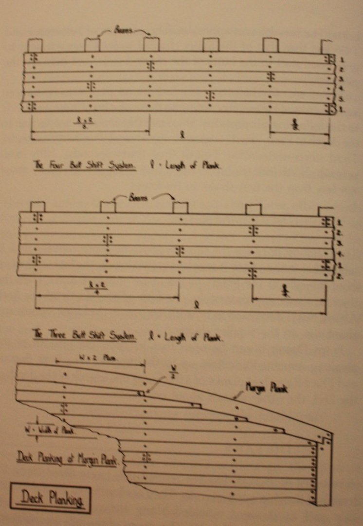
He goes on to say that these shift patterns were necessary so the deck was not weak.
Allan
-
On 2/28/2024 at 5:31 PM, ERS Rich said:
Mucho important. The instructions probably do not emphasize that planks must be tapered. If needed look it up here, along with the concept of planking belts. An understanding of planking is probably the biggest thing one needs to learn when getting started. See my Constitution log, link below for pointers.
This is an incredibly important comment if a realistic model is part of your goal. In addition to the planking tutorials in the Articles data base here at MSW, if you have not already done so, study the four part tanking tutorial videos. Part one-- https://www.youtube.com/watch?v=KCWooJ1o3cM
Allan
-
Fàilte to MSW Gaz!!!!
Allan
- Keith Black, Gaz and mtaylor
-
3
-
2 hours ago, paul ron said:
lets not split hairs...
Hi Paul,
😀Not splitting hairs at all, just genuinely curious about the origins of terminology in the various eras and how, why and when some terms changed.
Cheers
Allan
- Keith Black and paul ron
-
1
-
 1
1
-
23 hours ago, paul ron said:
im building the flying fish clipper 1851. my plans, and after searching, i cant find any references to lights used on these ships
Just saw this post string and it brings up a terminology question as it was confusing in the first post. On English ships of the 17th century and into the 19th century (maybe earlier and later??) lights at the galleries and stern are the windows, not lamps or lanterns. Did this change circa 1855 as Pat mentions above such that the lanterns and lanterns on clipper and other ships were then called lights and the lights became known as windows or some other term such as bullseyes and portholes? Not a major thing, just curious. Tx
Allan
- Keith Black and mtaylor
-
2
-
Rob,
I TRULY hope all goes well for you!!
I have recently been doing some more studying of the Portland class as the 50 gun ships of any era are probably my favorites.
This is very late to the table--- Christian mentioned I think that Portland has the conventional framing pattern with double and single frames. This made sense to me but I just noticed a few days ago that on the framing plan for Portland there is a note that there are to be dry pieces of oak between every frame. They show an example of these pieces at station O. Whether this carried over to the later ships of the class I have no idea, but barring additional contemporary information to the contrary, I think one could argue there were no double frames.
Allan
- scrubbyj427, mtaylor and Mark P
-
3
-
1 hour ago, Ingo said:
Mossel Bay, South Africa,
Welcome to MSW Louise!! Made it to Cape Town, East London, and Durban way back in the day, but unfortunately missed Cape St. Francis (surf's up), and Mossel Bay both of which we wanted to visit. Beautiful part of the world, sharks and all.
Allan
- Keith Black, mtaylor and AJohnson
-
3
-
Wherever you decide to paint the bottom, the line would usually be parallel with the earth. Your photo appears to have a curve to the tape. There are hundreds of photos you can check out of contemporary models on the RMG Collections site, including the one at https://www.rmg.co.uk/collections/objects/rmgc-object-66510
In any case, if you want a very clean line, before painting, spray a couple clear coats which will seal the tape at the edge. Afterwards, after you paint the color and it has dried peel off the tape it will be a very straight line.
Allan
-
1 hour ago, Thukydides said:
In our modeling world, that seems impractible
I agree with Daniel that fixing the yards makes things easier and it will also provide security over the many years to follow. I use small diameter brass rod as described in The Fully Framed Model volume IV. Most importantly follow Daniel's advice about pre rigging as much as possible on the yards before hanging on the masts. For a LOT of great detail on rigging my two favorites are James Lees' Masting and Rigging and David Antscherl's The Fully Framed Model volume 4 and his sail making supplement. The order of dressing in TFFM is more user friendly for modelers than the OOD in Lees which I believe was that which was done on actual ships.
Allan
- mtaylor and Thukydides
-
2
-
WELCOME TO MSW!!!!
Allan
- Keith Black and mtaylor
-
2
-
Blacky,
I have all of the Ardent (1764), Ardent (1782) and Anson 1781 plans in high resolution downloaded as they are available on the Wiki Commons site. With the deck plans and Inboard profile you should have everything you need. I would attach here for you but each is 35mb to 70 mb. Go to the Wiki site https://commons.wikimedia.org/wiki/Category:Ship_plans_of_the_Royal_Museums_Greenwich Pages 1 and 4 have all the drawings for the above vessels in high res. You can also contact Bucklers Hard to see what information they have on Agamemnon. They were very helpful in the past when I was doing a lot of research on Euryalus which was also built at Bucklers Hard.
Allan
-
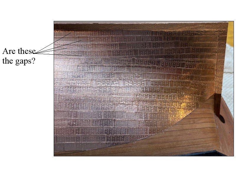
8 hours ago, Yabuhebi said:
I may be lost in the terminology here. I know that I have tapered the stern to accommodate the addition of both plankings.
Hi Chris
Sorry if my question raised more questions. It is probably easier to look at similar discussions here at MSW when this was raised on another build. I suspect your kit does not address this as only two kit makers I now of appear to give this any attention even though it is found on virtually every RN ship in the 17th to early 19th centuries. https://modelshipworld.com/topic/34577-taper-of-the-keel-stem-knee-of-the-head-and-stern-post/#comment-986943 and https://modelshipworld.com/topic/32748-hms-bellona-by-nearshore-corel-1100/page/2/#comment-982279 Post #40
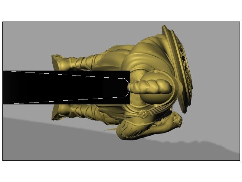
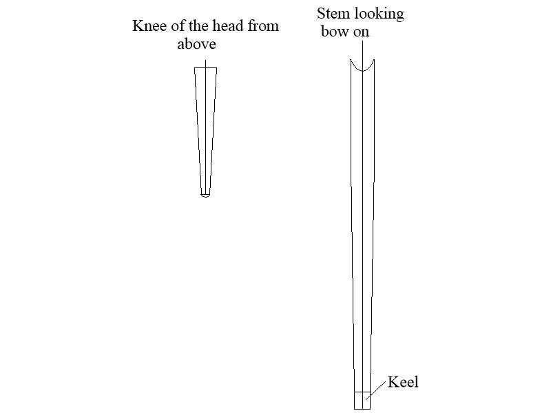
Just as the stern post narrows in breadth from the upper portion down to match the keel, the stem also reduces in breadth so it matches the breadth of the keel where they meet at the boxing joint as the keel tapers in breadth for and aft from midships. Looking down on the knee of the head from above it also tapers from the stem down to about 6 inches at the area of the figure head on a 74. I do not have my books with me so not sure on a first rate, but I am guessing it would be similar. In the end, as with the majority of kit makers, most model builders are not aware of the tapering or are not overly concerned with it so it will likely never be noticed if not done. The downside is that the figure head, if a carved person will surely be bowlegged. 😀
Allan
-
Looking good Chris. Hard to tell from the photos if the knee of the head and stem have been tapered which would be a significant amount. Do the instructions indicate how much the stem is to be tapered vertically and knee of the head from the stem to the seat of the figure head?
Allan
-
At your scale, the method of assembly of the ratlines themselves makes sense but how do you secure/wrap the shroud pairs around the mast? What is the spacing from ratline to ratline?
Many thanks
Allan
-
-
On 2/25/2024 at 11:29 AM, rvchima said:
Spoiler Alert - I am about to copper the hull. The Sphinx was coppered in 1781. Would the copper go under, over, or around the iron reinforcement plates? Same question for the rudder hinges.
FWIW Bellona coppering. https://www.rmg.co.uk/collections/objects/rmgc-object-66299 Copper is over the rudder hardware.
-
Hopefully Ed Tosti (Naiad and Young America) sees this and can add some information. I had the privilege to visit him at his home quite a few years ago and see his collection of miniature military figures prior to his fabulous work on the ship models and books. I have never seen better representation than his collection. Maybe PM Ed to ask if he can lend some advice/methods based on his experience.
Allan
-
Hi Eric
If the hull is going to be painted over or otherwise covered, it does not really matter. But if the planking is going to be uncovered look at the planking tutorials in the article database here at MSW and you will see instructions on starting with lining off the hull and then planking starting with the wales then working down to the garboard and up to the highest strakes. https://thenrg.org/resources/Documents/articles/APrimerOnPlanking.pdf There are differences in some kits' planking, including OcCre where they have planks that are not properly tapered so some of them do not end at the rabbet as they would in real practice (with the exception of a drop strake or stealer if needed.) If you have not already seen them, these four videos are well worth watching as they give an alternative to spiling that works well Part 1 --- https://www.youtube.com/watch?v=KCWooJ1o3cM
Allan
- mtaylor and SiriusVoyager
-
2
-
-
11 hours ago, Darius359au said:
I think it's on the NMM Pegasus quarterdeck plan, there's the large section with "grating" written
The inboard profile confirms these are gratings and a ladder way as there is nothing above the deck indicating a skylight which could be instead of, or in addition to, gratings and ladderway. Pegasus was launched in 1776 and fitted out in January 1777 and the RGM plans were drawn between late 1776 and early 1777 so might be as-built plans. If you look at the Pegasus drawings from 1775 (https://www.rmg.co.uk/collections/objects/rmgc-object-84572) there are differences between this design drawing and the drawing made at about the time of her launch. (https://www.rmg.co.uk/collections/objects/rmgc-object-84573)
Greg makes a good point that the clerestory-style companionway may be appropriate, but I just wondered why the kit plans do not match the originals as there is nothing to indicate there was such a companion way.
In TFFM David does state that the inclusion of a companion top is a thorny subject, He goes on to say ships-of-the-line had clerestory style lights from about 1750 that could be removed and replaced by gratings. And, as Greg points out TFFM makes note there was a reference from 1779 that allowed sloops of 300 tons to have one companion. As Pegasus sunk two years before that, I am not totally convinced she ever had one, but as with so many things in our hobby, who knows?
No matter, I agree with Greg that they add character to the deck layout and you should go with what makes you happy.
Allan
- Knocklouder, mtaylor, Keith Black and 1 other
-
4
-
Hi Richard
This is really interesting. Neither of the QD or inboard profile contemporary plans of Pegasus 1776 show a skylight, just gratings and ladderways. Perhaps the skylight was added later but she sunk 10 months after being launched. I thought maybe the draftsman just left it off the drawing but, while it is a larger ship of which there was a Pegasus (28) 1779 in the group it is very clearly shown on the Enterprize (28) 1774 drawings (second set below). I would think that if there was supposed to be a skylight when launched, it would be on the original plans. If you just leave it off the model, it can be argued, based on contemporary evidence, it never existed.
Allan
https://www.rmg.co.uk/collections/objects/rmgc-object-84573
https://www.rmg.co.uk/collections/objects/rmgc-object-84575
https://www.rmg.co.uk/collections/objects/rmgc-object-83179 also available in high resolution on the Wiki Commons site
https://www.rmg.co.uk/collections/objects/rmgc-object-83181 also available in high resolution on the Wiki Commons site
- Keith Black and mtaylor
-
2
-
3 hours ago, No Idea said:
I have never successfully used water to unglue my work.
If the piece is already glued on the model I tape a soaking wet paper towel to the part and rehydrate it every few hours. Takes overnight and then some at times. Another example, but purposely gluing parts together that will need to be separated....... when I have to make very small strips of wood such as window frame pieces that are about 0.025" square at 1:64 I thickness sand a board to that thickness then cut strips with a rule and scalpel. These are never exactly at the same thickness as the original board, but too small to take through the thickness sander one at a time. I glue 5 or 6 pieces side by side with the hand cut edge being the wider face of the glued up strip. I then can run through the sander without worries. Once done I soak the assembly for an hour or so and the glue melts and the pieces come apart very easily. Takes a little scraping of the glue afterwards but otherwise a relatively easy task. Thicker pieces take longer but can be done. The hard part for me is having patience.
Allan

Hello from British Columbia!
in New member Introductions
Posted
Welcome aboard! Is your dory kit the Antscherl designed kit from Model Shipways. If so, you picked the best starter available. With the three kit series, you will learn great skills and habits that will carry over to other very accurate and more complex models such as those from Syren Ship Models.
Allan