

NavyShooter
-
Posts
441 -
Joined
-
Last visited
Content Type
Profiles
Forums
Gallery
Events
Posts posted by NavyShooter
-
-
Function will define form.
Size will define cost.
Are you turning wood? Are you turning metal? How big an item?
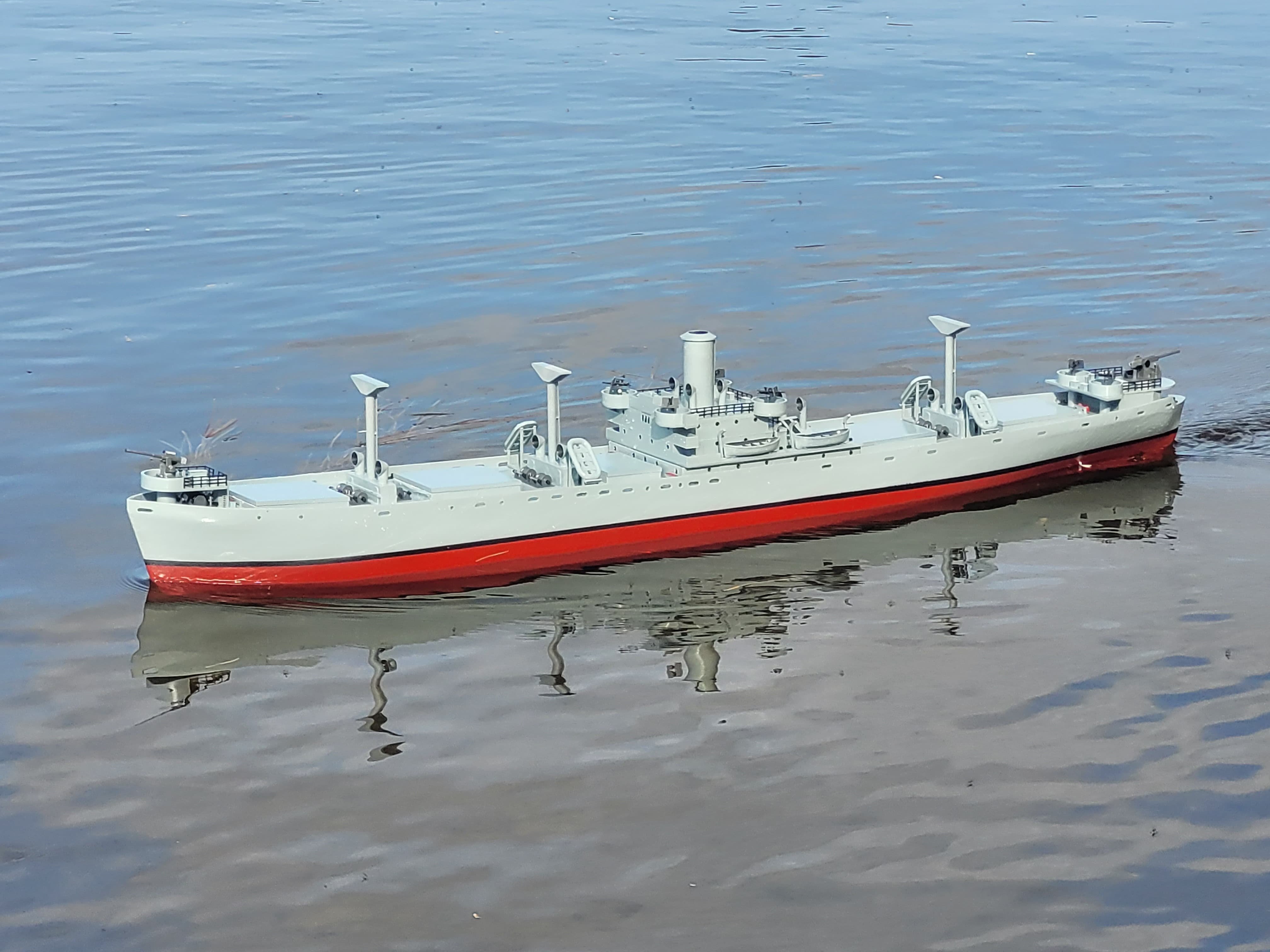
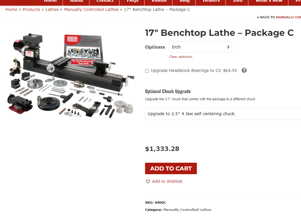
I've owned a Unimat, Taig, and a Sherline over the years. I upgraded to a used Southbend 10K, and have moved since then to an import 10x30 Lathe that didn't have the 'issues' that an old high school shop class beater lathe has in terms of wear and abuse.
If all you're turning is cannons and bushings from brass, then a Taig or a Sherline will do you OK.
If you're planning to build something large (bigger than about 1/2"), made of steel, or plan to do anything that's threaded, then you need bigger than that.
There is a lot of info about the import 7x14 lathes that are out there - they're cheap, and you get what you pay for in terms of quality. You'll find yourself working on upgrading/fixing the lathe more than you do building parts on the lathe.
In the end, I dumped about $1500 into bits and pieces for my Sherline. I had the milling attachment, the extended bed, and so on. It was still only barely capable in terms of what I wanted to do.
I now have a 10x30 Precision Matthews lathe, and it's capable of doing everything I've tossed at it so far. Cost me about $4K (Canadian) landed to my door with all the import fees/taxes/etc, and it was well equipped - both 3 and 4 jaw chucks included.
For $1500, you can get a Grizzly 8x16" lathe - 8" x 16" Variable-Speed Benchtop Lathe at Grizzly.com
That's less than $200 more than the biggest Sherline mini lathe, with a heck of a lot more capability.
To be honest, if you've got the space for a Sherline, you've got the space for the Grizzly, and it's a heck of a lot more machine.
NS
- mtaylor, Bob Cleek, Ryland Craze and 1 other
-
 4
4
-
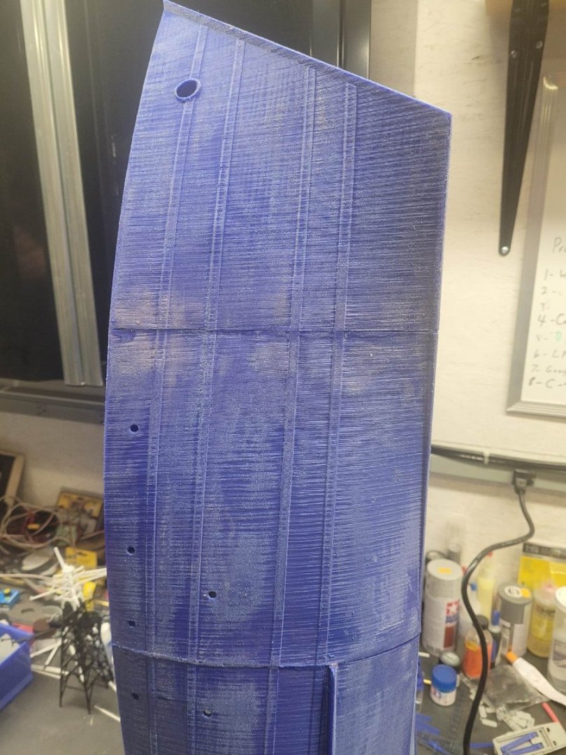
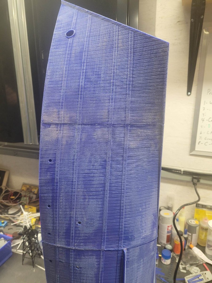
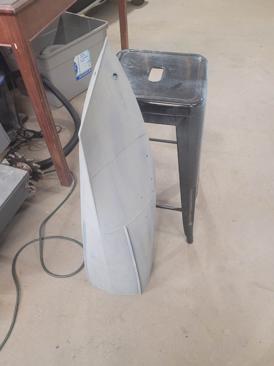
The printing is substantially complete - I have a few detail bits left to go (boats, etc) but have moved the 'bulk' of the kit out to the garage to get things started.
Here's the first bit of sanding and a layer of primer on the 'bow half'.

- yvesvidal, GrandpaPhil, Canute and 3 others
-
6
-
1 hour ago, Prowler901 said:
Excellent looking prints. What filament are you printing with? I have the Ender 3 Max. Still tweaking it's settings for best prints.
Todd
I use PLA that I get at the local shop - Eurekatek. They're just around the corner from me.
My experience is that their Royal Blue is absolutely delightful to print with.
-
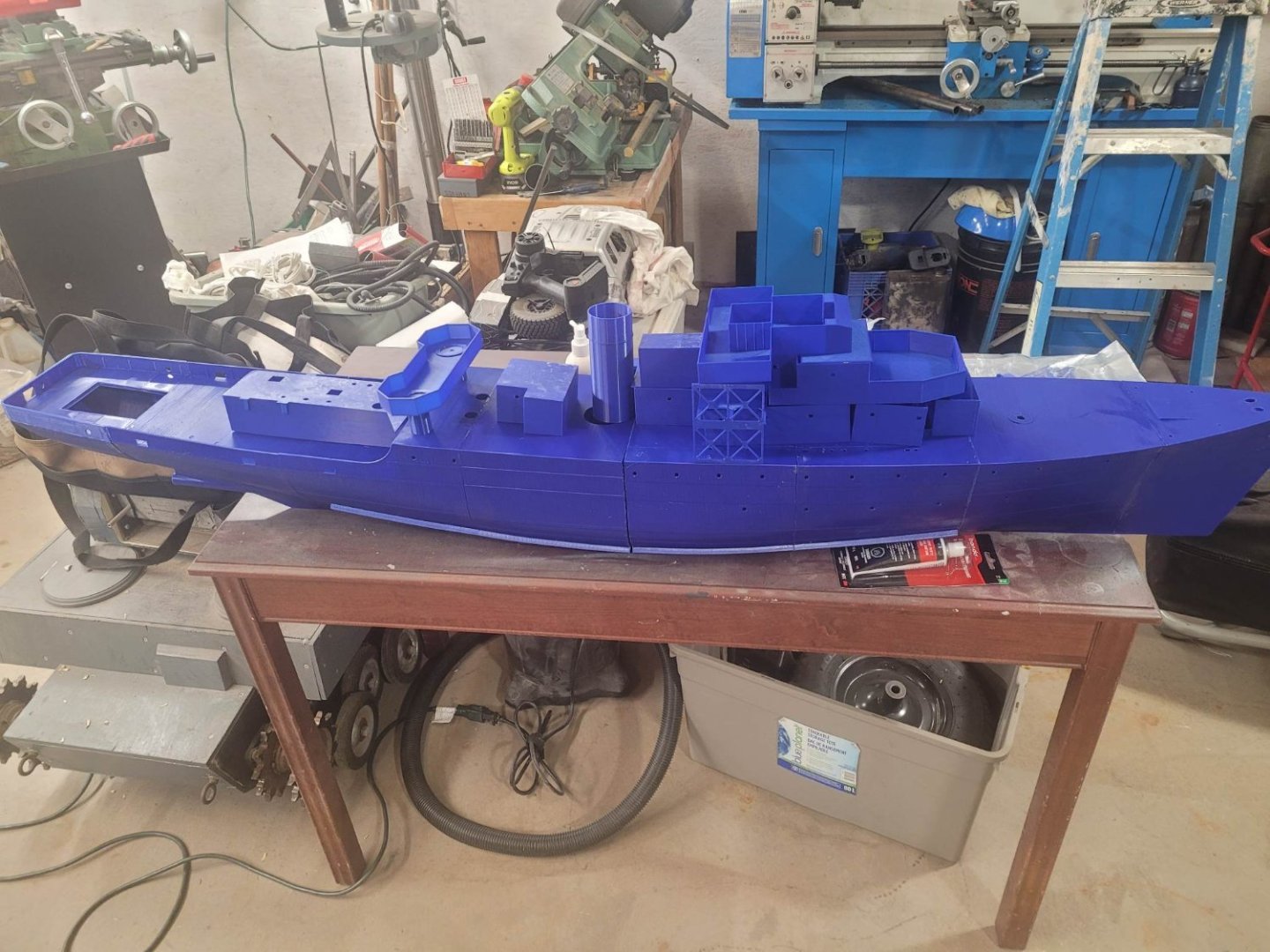
Of note....this boat is going to be 63 inches long. For some reason I didn't think it was going to be that huge.
On the other hand, the Titanic is going to be over 8 feet long when it's all done...and the first module for it is now on the printer.
- Canute, Prowler901 and mtaylor
-
3
-
Welcome aboard Squid!
I'm an ex-RCN Skimmer type that spent my career on the East Coast. I was a SONAR tech (Maintainer - not an operator) so if you're familiar with Monty Python, I'm the guy who fixed the machine that goes "PING".Enjoy your time here on the forums, I'm sure you'll find your niche! The amount of expertise here is amazing to me at times!
NS
(Brad)
- Keith Black and Ryland Craze
-
2
-
-
-
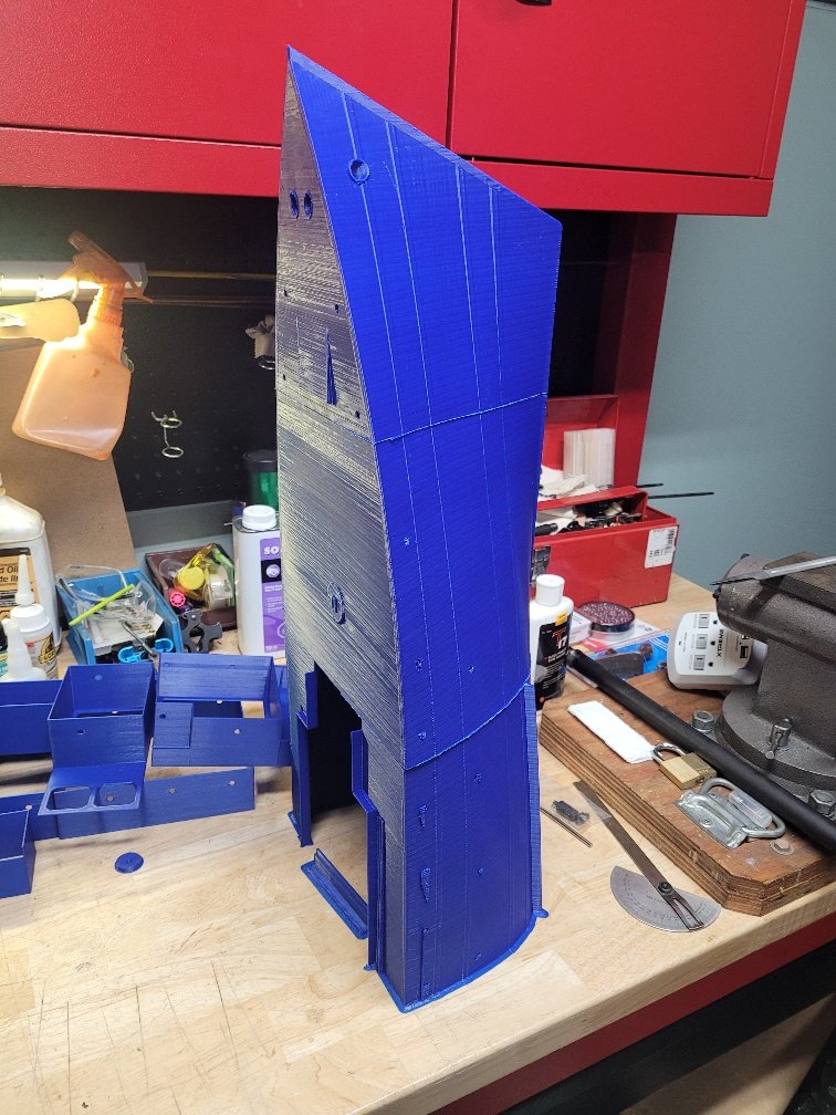
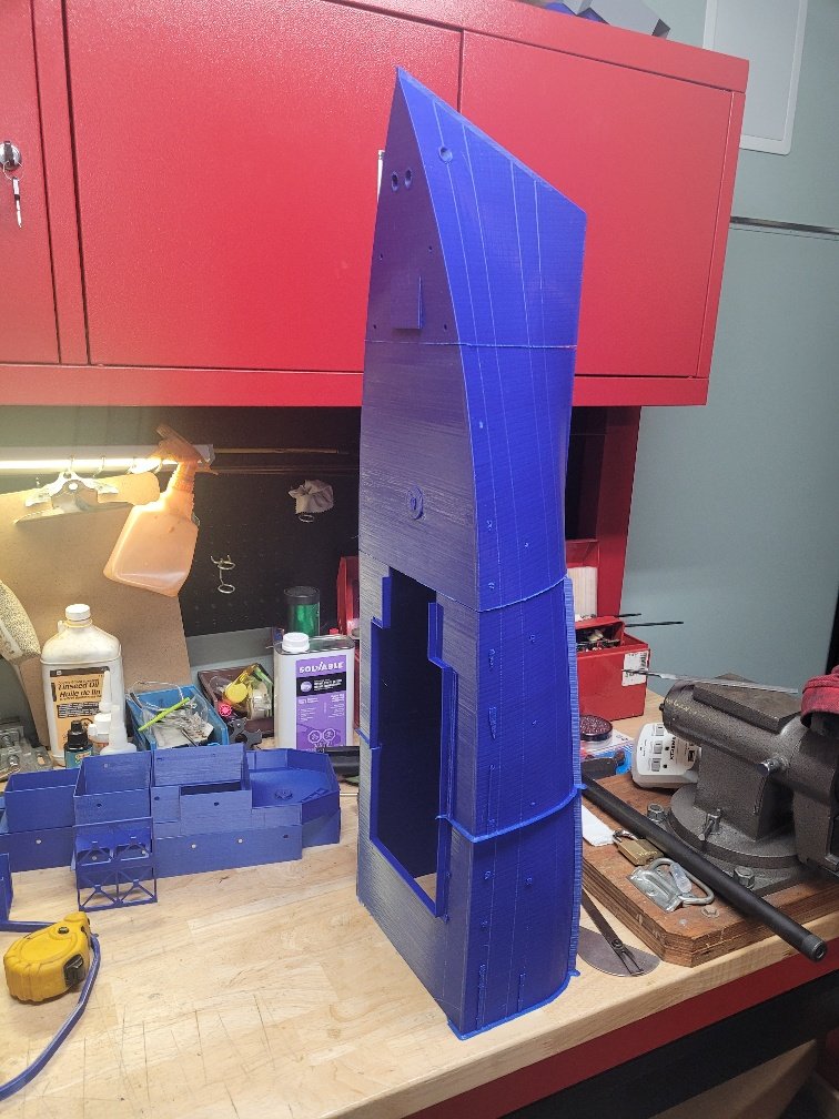
And....25.5 hours into a 26 hour print...things went off the rails and I'm having to redo the last module.
Alas!
- Prowler901, Canute, mtaylor and 1 other
-
 4
4
-
-
-
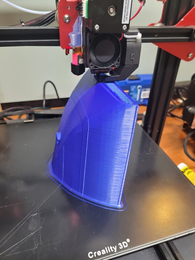
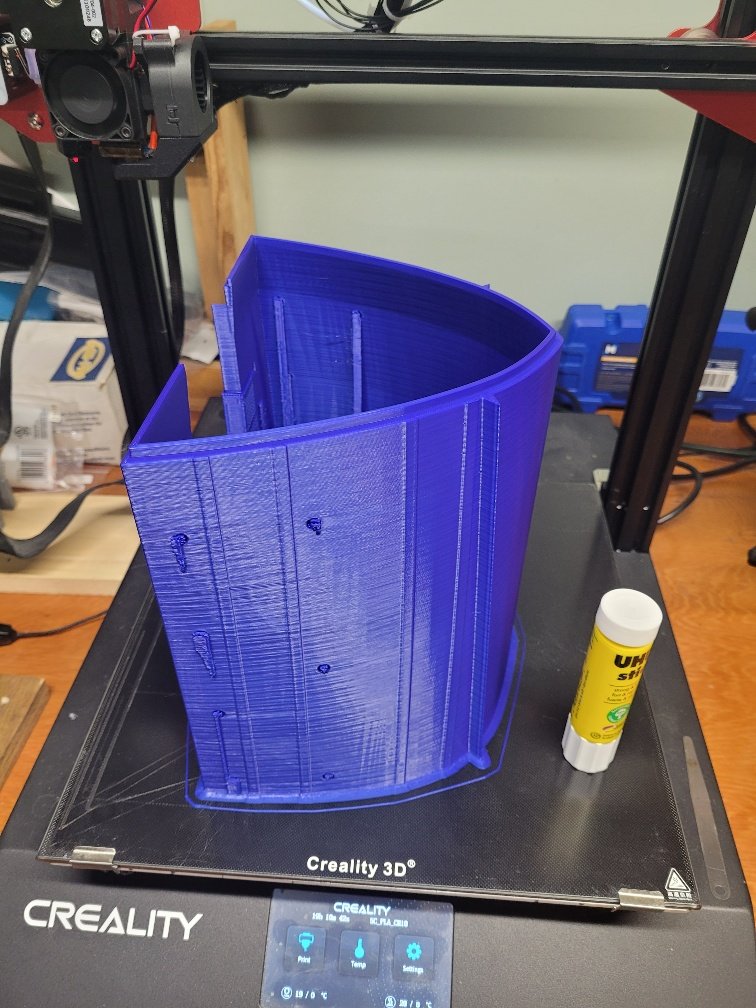
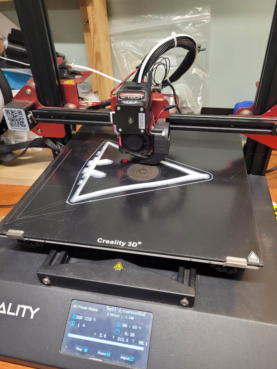
Here's how the printing is going....module 6 of 8 is going to be done later this afternoon. I should have the hull printing done early next week!
- GrandpaPhil, goatfarmer11, ccoyle and 7 others
-
9
-
 1
1
-
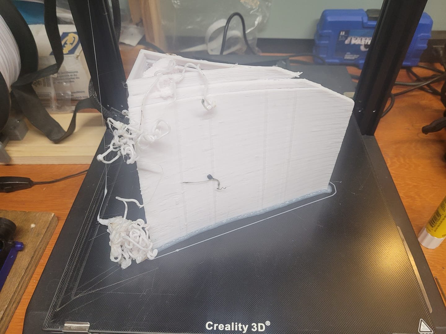
And, in keeping with the way my life usually goes, here's the beginning, and the failed end of one of the modules being printed.
This was still in the 'troubleshoot the new-to-me' printer stage, so I'm not hugely concerned about the failed print. It helped me figure out the real core problem, and things are trucking along now. I've got 2 modules completed, and the 3rd will be done in about 3 hours.

- Prowler901, Canute, mtaylor and 2 others
-
5
-
Good evening gents,
I've decided to take on a project - I'd originally purchased the print files from Bensworx last year to build a version of his Castle Class Corvette in 1/96 scale as a fleet-mate for my HMCS Bonaventure project. That said, scaling the print didn't work so well. The hull wasn't thick enough and many of the superstructure parts scaled down to a single layer (0.4mm) thick plastic which was not thick enough to be workable. So, to the backburner it went.
Then I saw this thread by King Derelict:
I enjoyed reading his work, but wasn't really in the mindset of building the Castle after the initial issues I had at 1/96 with her. Additionally, due to the size of the prints, they'd be a tight fit on my Prusa printer.
Then. I had a change of heart.
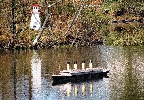
We had our monthly modeling guild meeting, and there were a couple of things that came up. First - our club normally maintains the RMS Titanic model that floats in the Halifax Public Gardens. Well, that model sank last summer, and needs some 'considerable repair work' to get her back suitable for service.
At the end of the meeting, we had a chat about getting the old model fixed up, or...should I try and print another one? So...I'm working down that path right now working with a 3D modeler to adjust his 1/1000 scale model to 1/100, and provide me with a hollow interior solid object that I can print, with hull sides of about 5mm thickness. At the same time, I found myself a 'new to me' Creality 10S Pro that I need to sort out - I'll need the larger printer (30x30x40 cm) to be able to print the Titanic hull modules, so I decided to print some of the Castle files as test-jobs.
Then I found out that the "Friends of HMCS SACKVILLE" organization in Halifax normally provide a model of the Sackville to be anchored out in the pond as well. The status of that model is uncertain...and I realized that I have a set of plans for a Castle Class Corvette....and...as luck would have it, an old shipmate of mine is now the XO of the Naval Reserve Division in St. Thomas Ontario - and one of the 12 Castles in RCN Service was the HMCS ST.THOMAS.
So.
Current 'plan' is to print the Castle, set her up as the HMCS ST.THOMAS, and once the hull files are clear of the bigger printer, I should be able to print everything else on the Prusa, as I switch the bigger printer over to hammering out the Titanic parts.
I've briefly mentioned to my buddy, and he may end up coming to Halifax for either the Launch, or the Recovery, as the intent is that the HMCS St Thomas will end up following him back to his unit for display.
We'll see how it goes.
For now, here's a picture of the original Titanic model in the pond at the park.
Here's the link to the 3D print files as well in case you're interested:
1 48 Castle Class Corvette RC Model Ship 3D model 3D printable | CGTrader
- Prowler901, GrandpaPhil, yvesvidal and 4 others
-
7
-
Not much to report lately - the searchlight print didn't go as planned, and the prop shafts only got shipped out to me on Thursday.
I expect I'll have them in hand in about 2 weeks.
- Canute, Keith Black and mtaylor
-
3
-
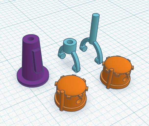
As the newest version of the Skegs is almost done printing (should be there when I get home tonight) I decided to do some design work for some search lights. We'll see if these will work out better than the file I got from a friend:
- Keith Black, GrandpaPhil, Canute and 4 others
-
7
-
Thanks!
A new version of the Skegs is heading to the printer in the basement in the morning - the aft end of them wasn't looking very streamlined, so that's been fixed up a bit.
- mtaylor, Canute and Keith Black
-
3
-
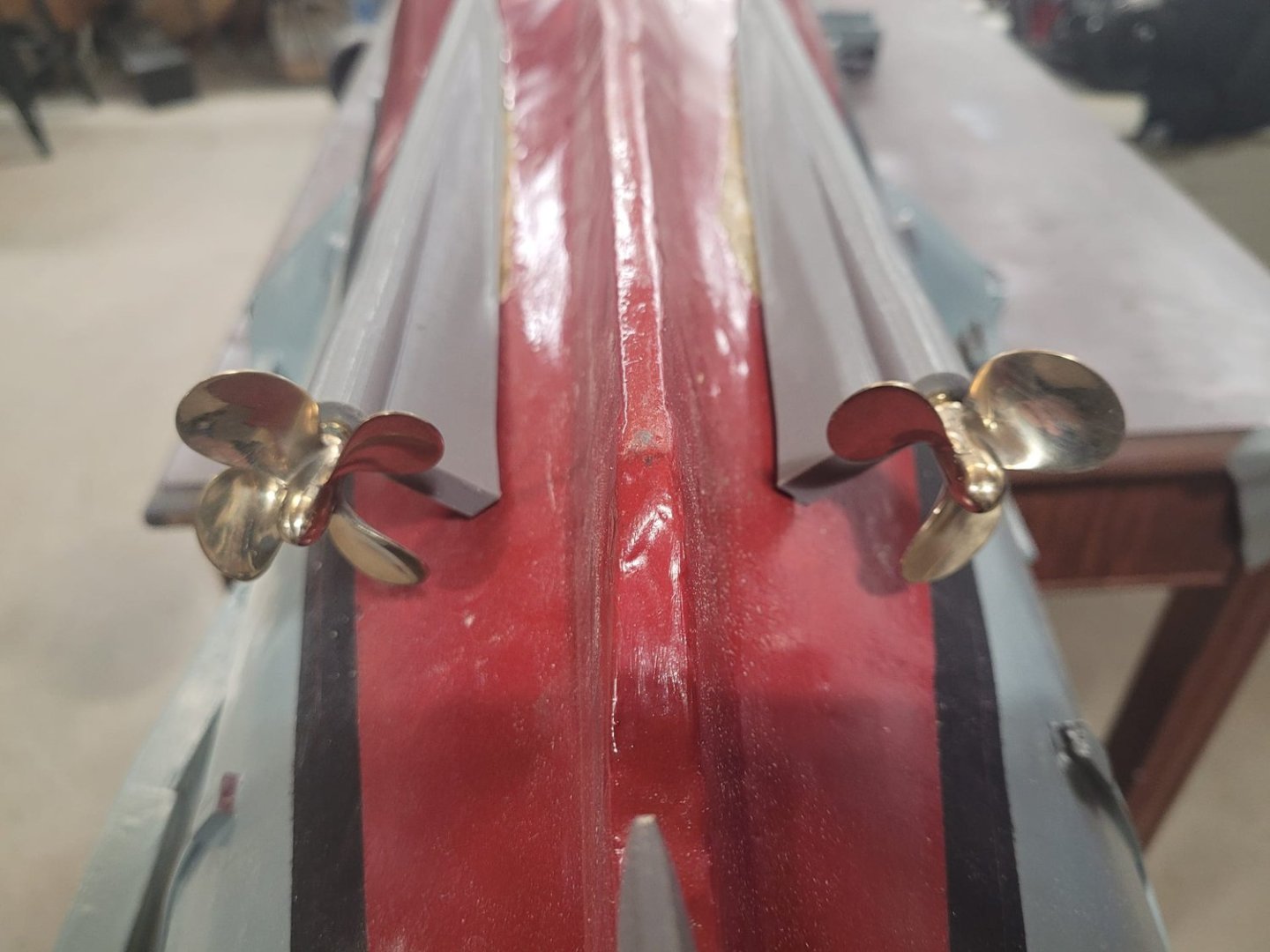
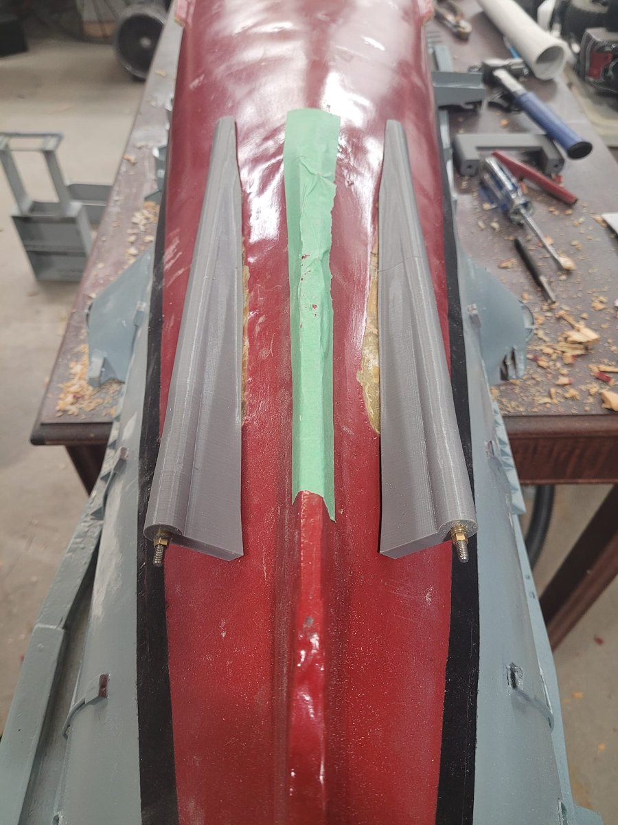
At the end of the evening, here's how things look. The replacement 3D printed Skegs are almost a perfect drop-in replacement. I'm shocked actually at how well this went together.
There is a small question of alignment and shaft length - I think I need to order a pair of 20" shafts, but I'll re-visit that tomorrow when I am able to thing about rebuilding her.I am quite pleased...yes, sanding, aligning, epoxying, fiberglassing and gell-coating are all still ahead, but damn....this is looking really really good.

-
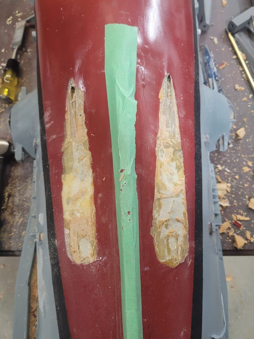
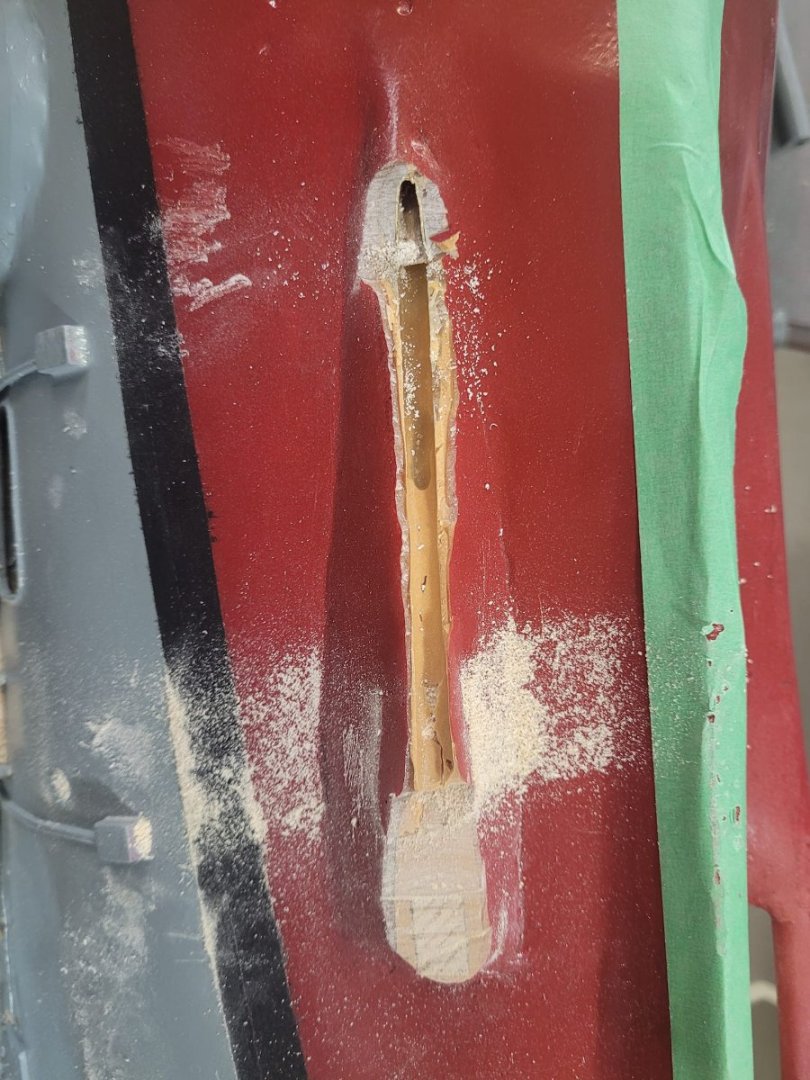
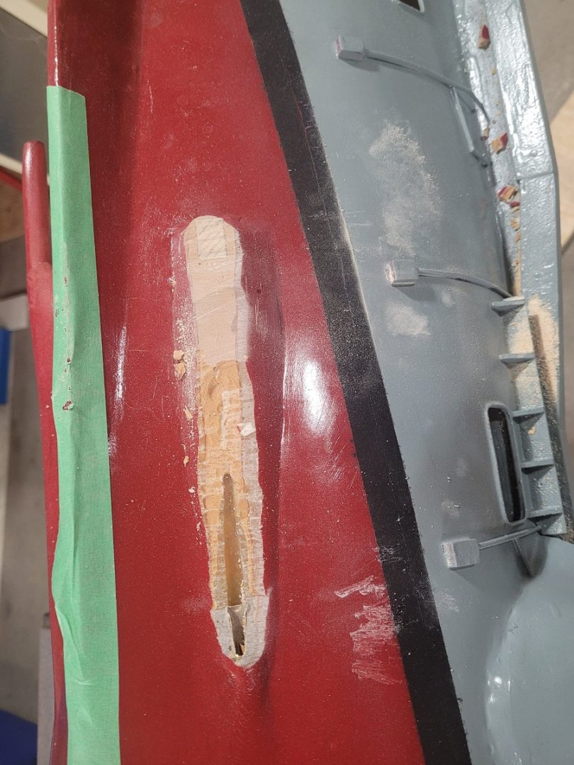
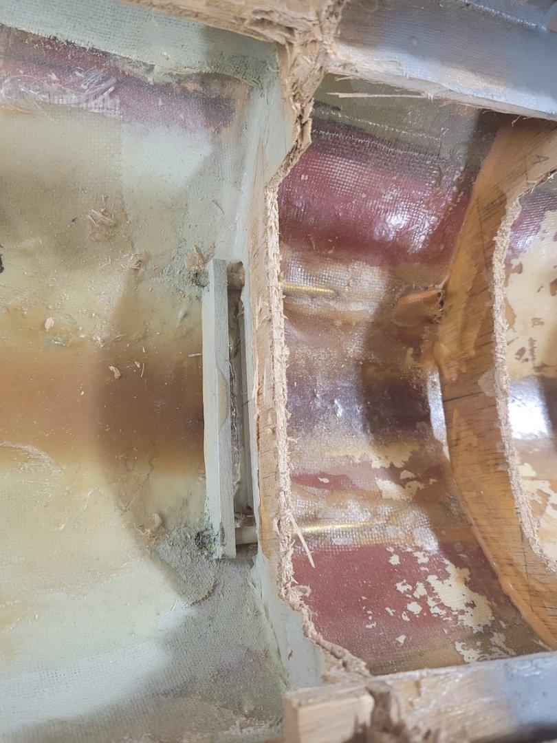
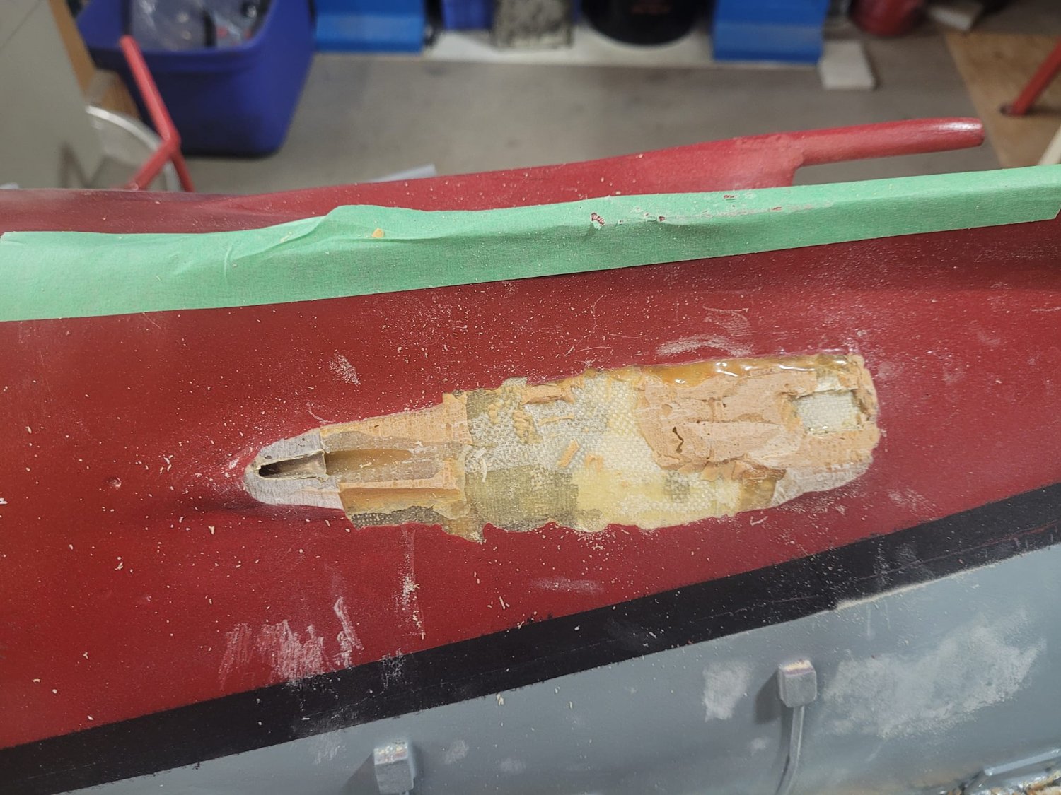
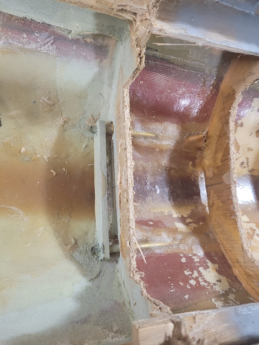
I then had the measure of the task, and of the durability of the hull, so I went to town...and about 20 minutes later, here we are...both old shafts stripped out.
There is still sanding to do - but this is the bulk of the destruction completed.
With the chisel, it took a lot less time that I'd anticipated.


- Keith Black, Canute, mtaylor and 2 others
-
5
-
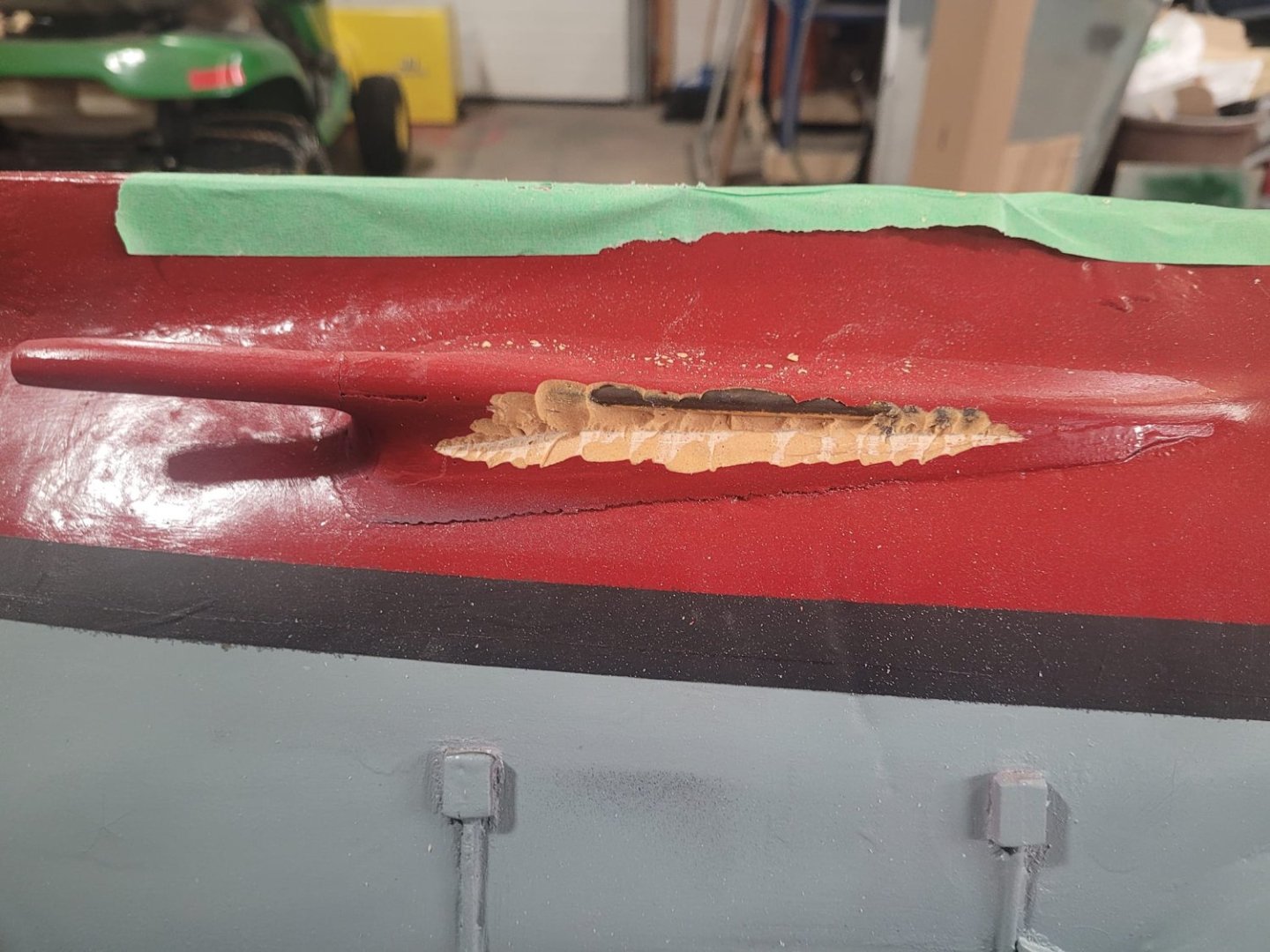
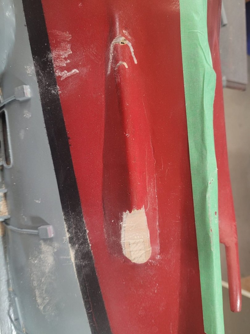
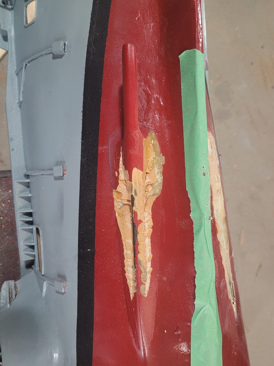
That is the assessment of the situation....here's what happened next. I pulled out the coping saw and started cutting. It was slow going.
After about 10 minutes with the coping saw, I decided that I needed to go big...so I dug out the old 1" Stanley chisel and an 8 ounce hammer, and started tapping away.
- Keith Black, GrandpaPhil, Canute and 2 others
-
5
-
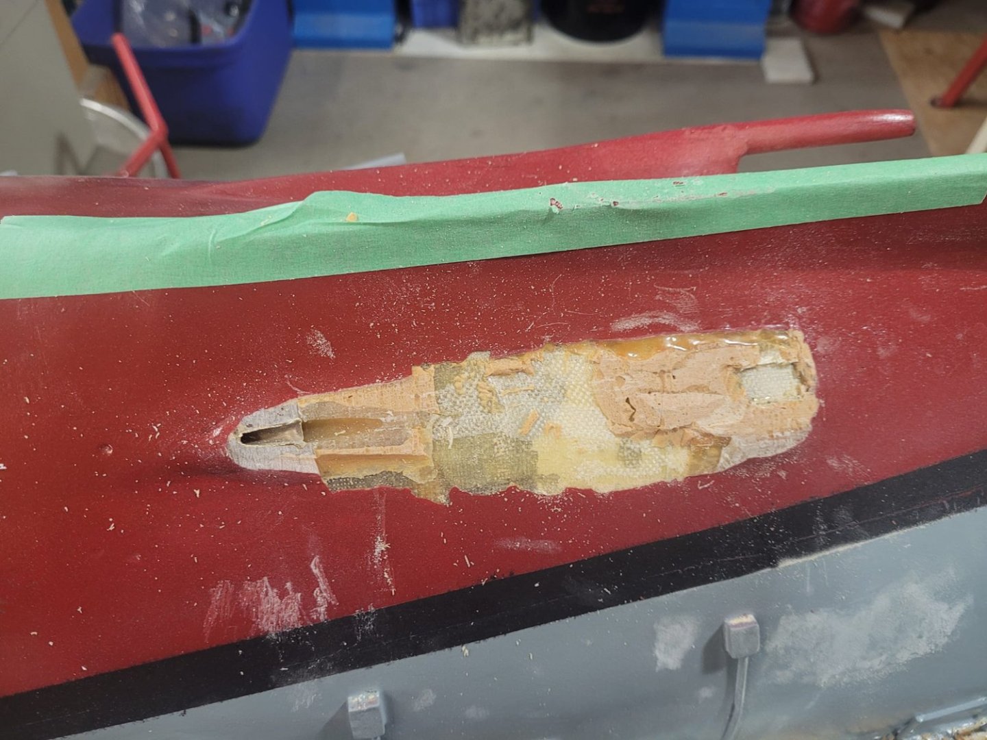
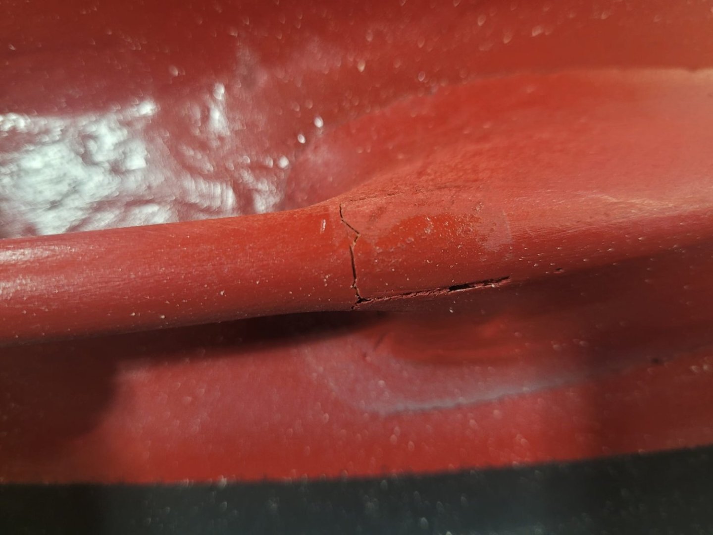
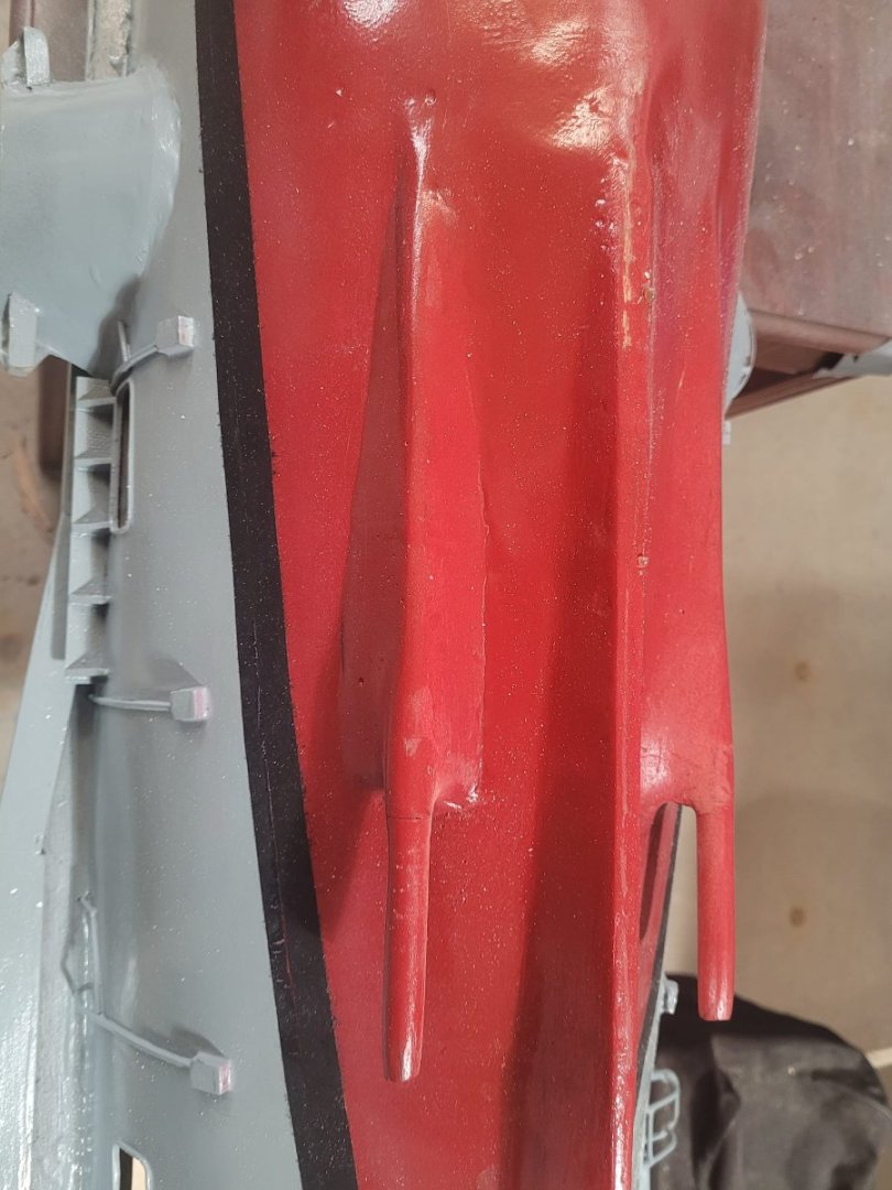
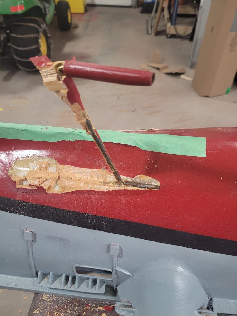
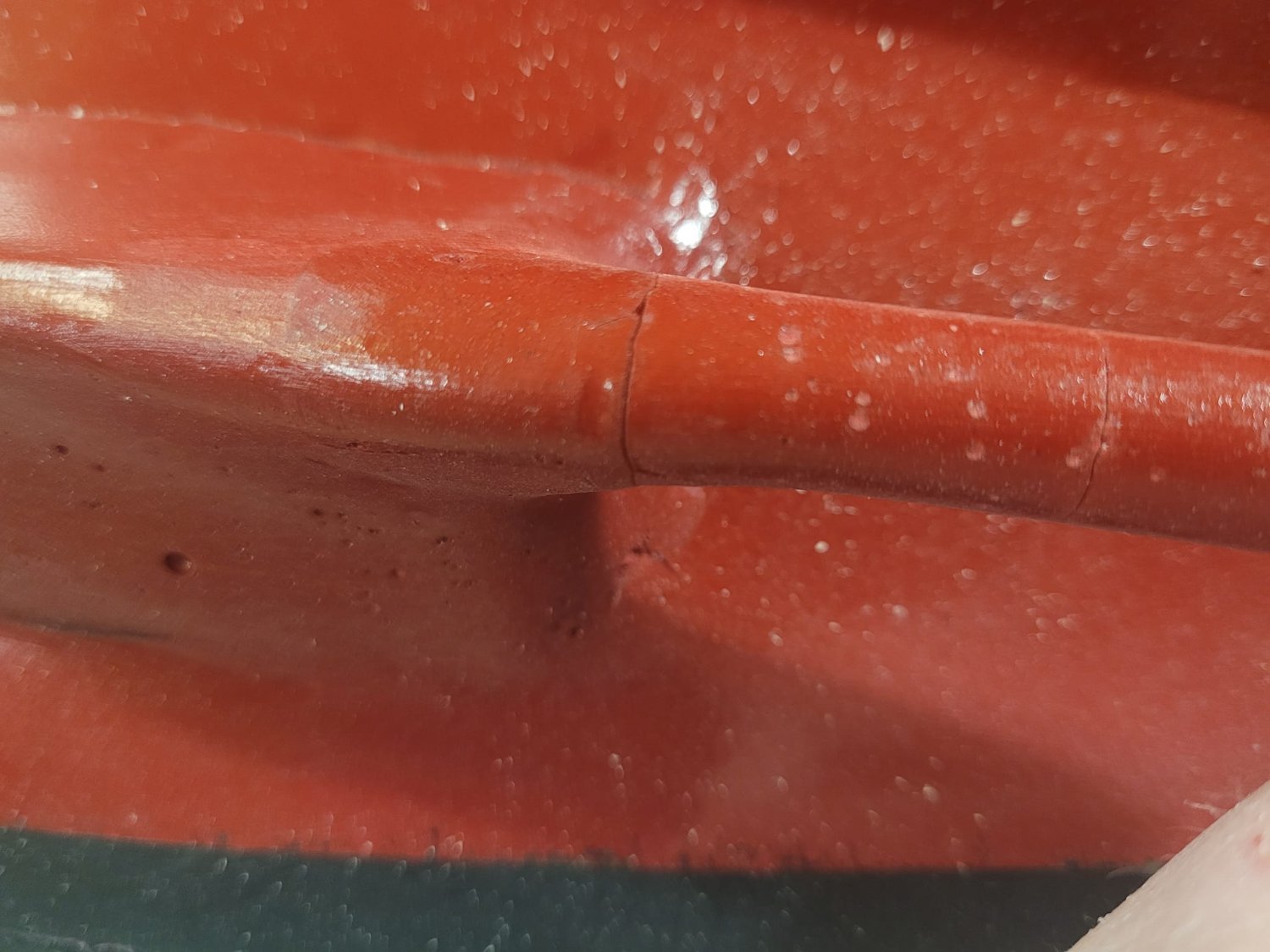
OK, so this is how my evening started. My wife had a dinner party with some of her friends over, so after picking a minion up from hockey, I had the chance to head out to the garage and putter about.
If you look closely, you'll see the cracks, and you can clearly see how the 'skegs' do not extend the whole length of the shaft line. The last 3.5" is free hanging, and you can see the cracks which resulted from that.


- Prowler901, Keith Black, Canute and 1 other
-
1
-
3
-
It was nice to have met you! You're welcome to come out to the boat club meetings at the Maritime Museum - 3rd Saturday of the month at 10 AM!
Now that the show is behind me, I can look at the next major milestone, which is, I think, getting the shaft lines and hull fixed.
One of the problems with the Bonnie model I'm working on is that the prop shafts aren't quite right. I tested the ship in a friend's swimming pool once and the props were poorly balanced, the shafts leaked, and were not proper stuffing boxes, rather, just a piece of 1/4" brass rod inside a snug fitting (but not tight, nor sealed) brass tube.
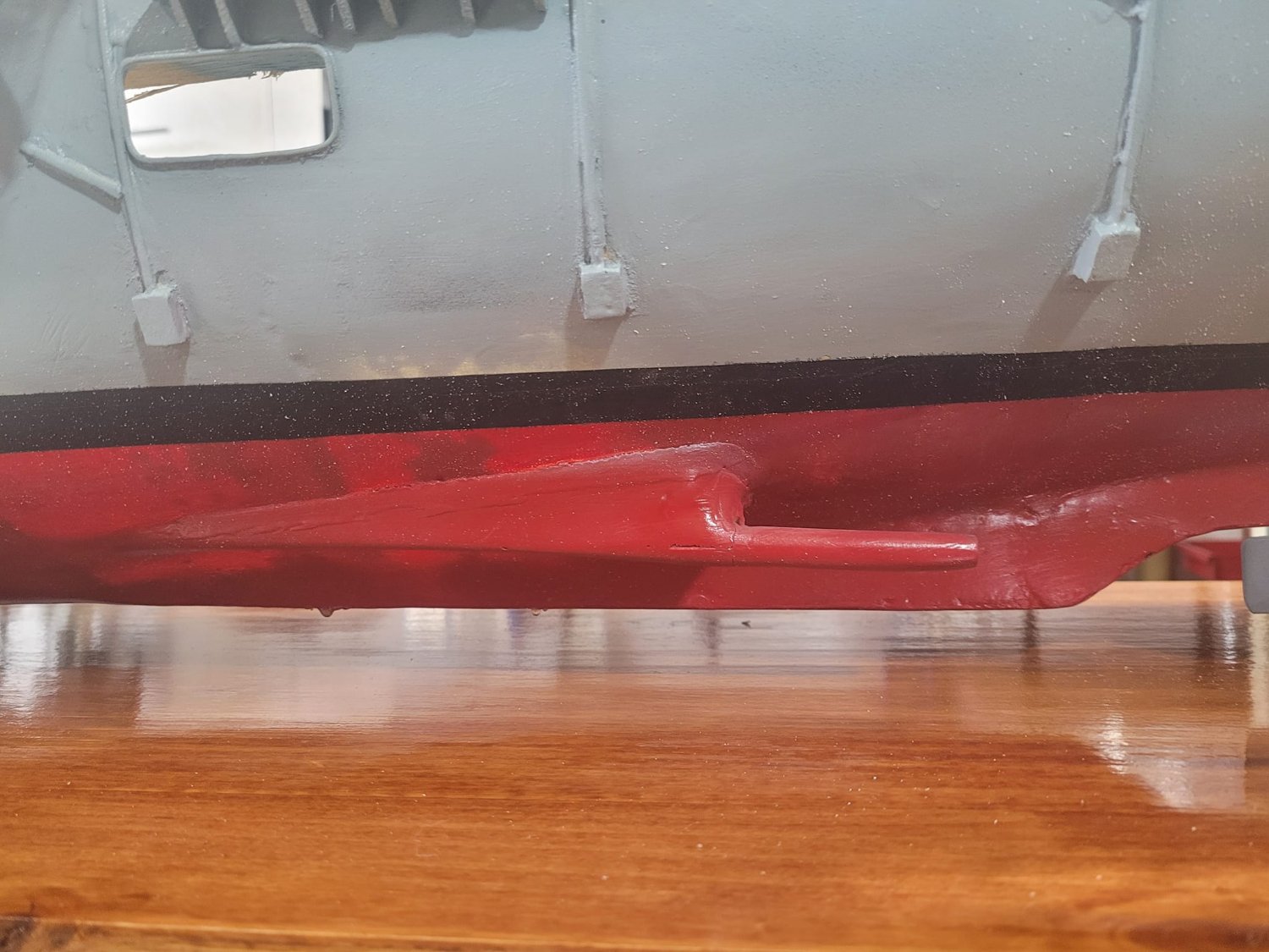
The other piece of the puzzle is that the 'skegs' that support the shafts end about 3.5" short of the end, so instead of support straight to the end of the shaft, instead there's a poorly balanced prop, with about 4" of shaft to flap around on. That's....not good.
So.
How to fix that? Can I get stuffing tubes that will fit inside? Not really. Still doesn't fix the skegs...so....the only answer I can see is to de-construct/destroy, then rebuild.
So.
I ordered a set of 15" long 6mm stuffing tubes with 4mm shafts, and a new set of props.
I've started with measuring some things...and realize that I need longer shafts than 15", but these will get things started at least in terms of fitting.
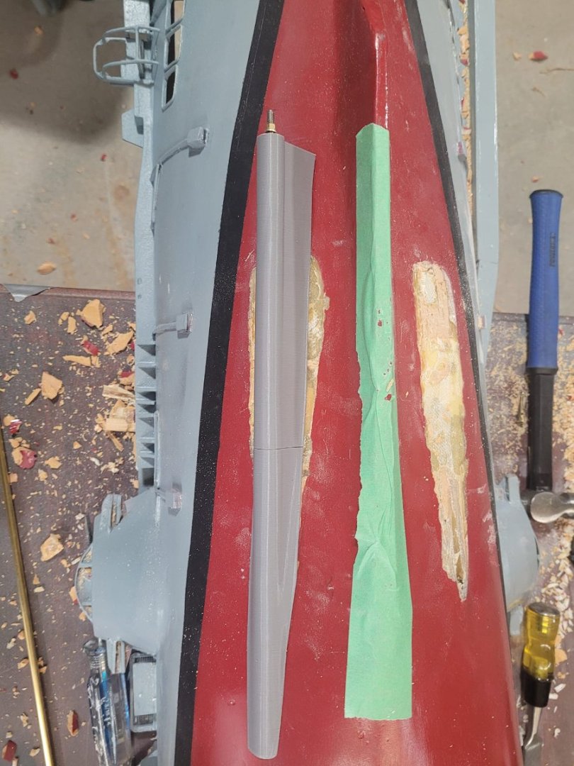
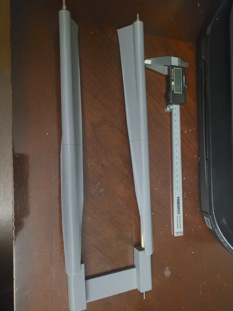
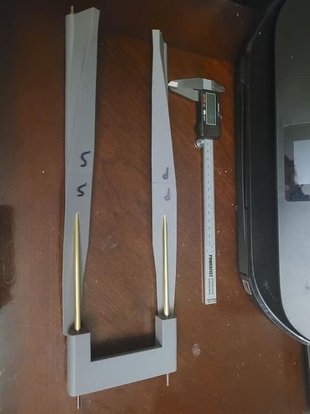
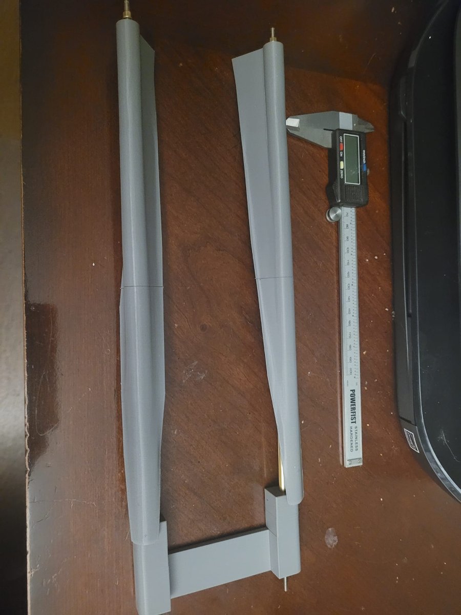
I'm going to end up having to remove the 'as fitted' skegs on the model, and replace them, and in pondering the right way to do that, I decided to try my hand at some basic 3D design - and I have been able to successfully loft/blend these together. There's still work to be done, but this is a good start.
With the Skegs made, I also made an alignment block for the shafts. This will hold the shafts in the correct alignment to each other as they are inserted and glued in place.
Intent is to glue/epoxy the replacement skegs on, then put a layer or two of fiberglass over top and blend them into the hull. We'll see how that all works out.
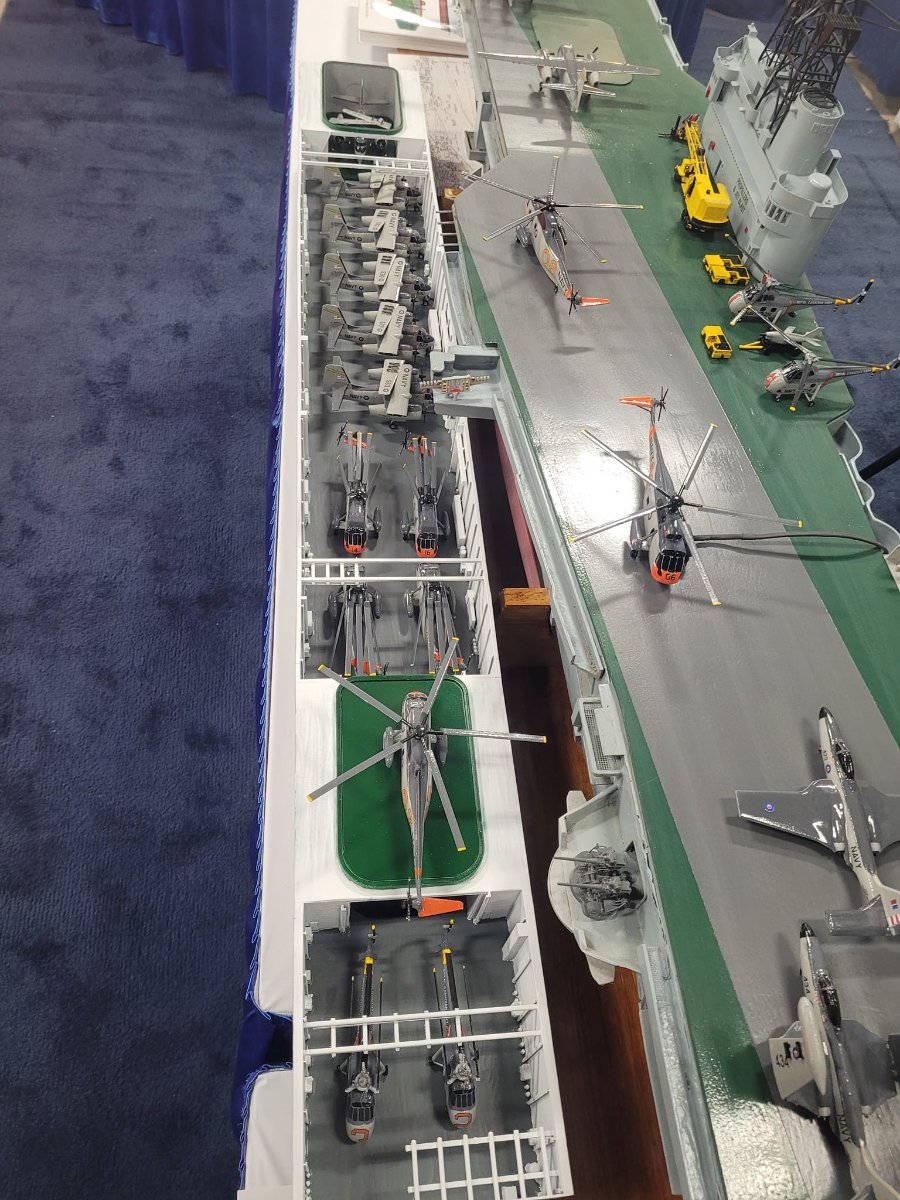
I'm thinking that there will be some pauses while waiting for weather warm enough to have the fiberglass actually set...so that'll give me time to detail out the hangar deck a bit as a background activity.

- Keith Black, mtaylor, Canute and 3 others
-
7
-
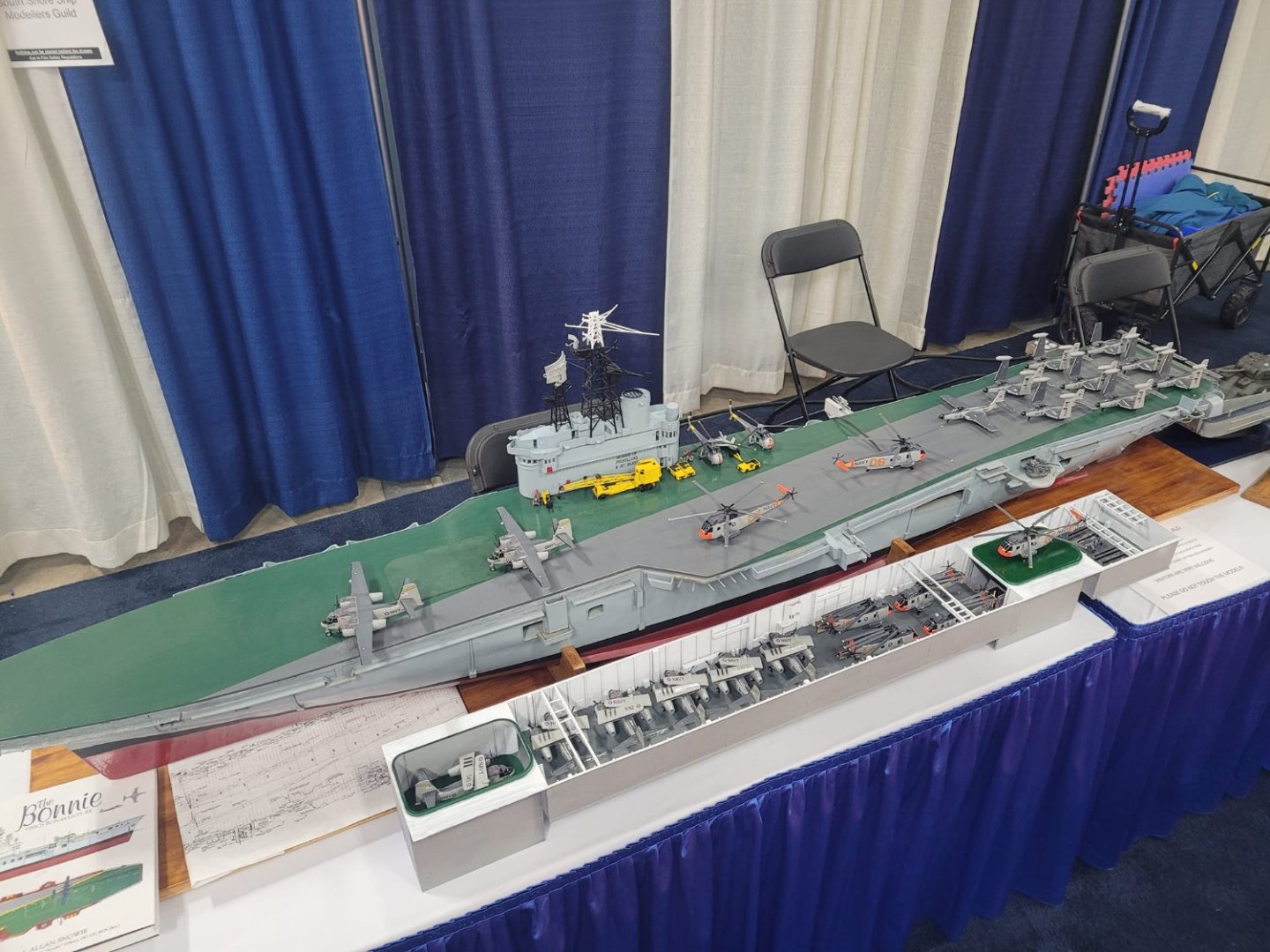
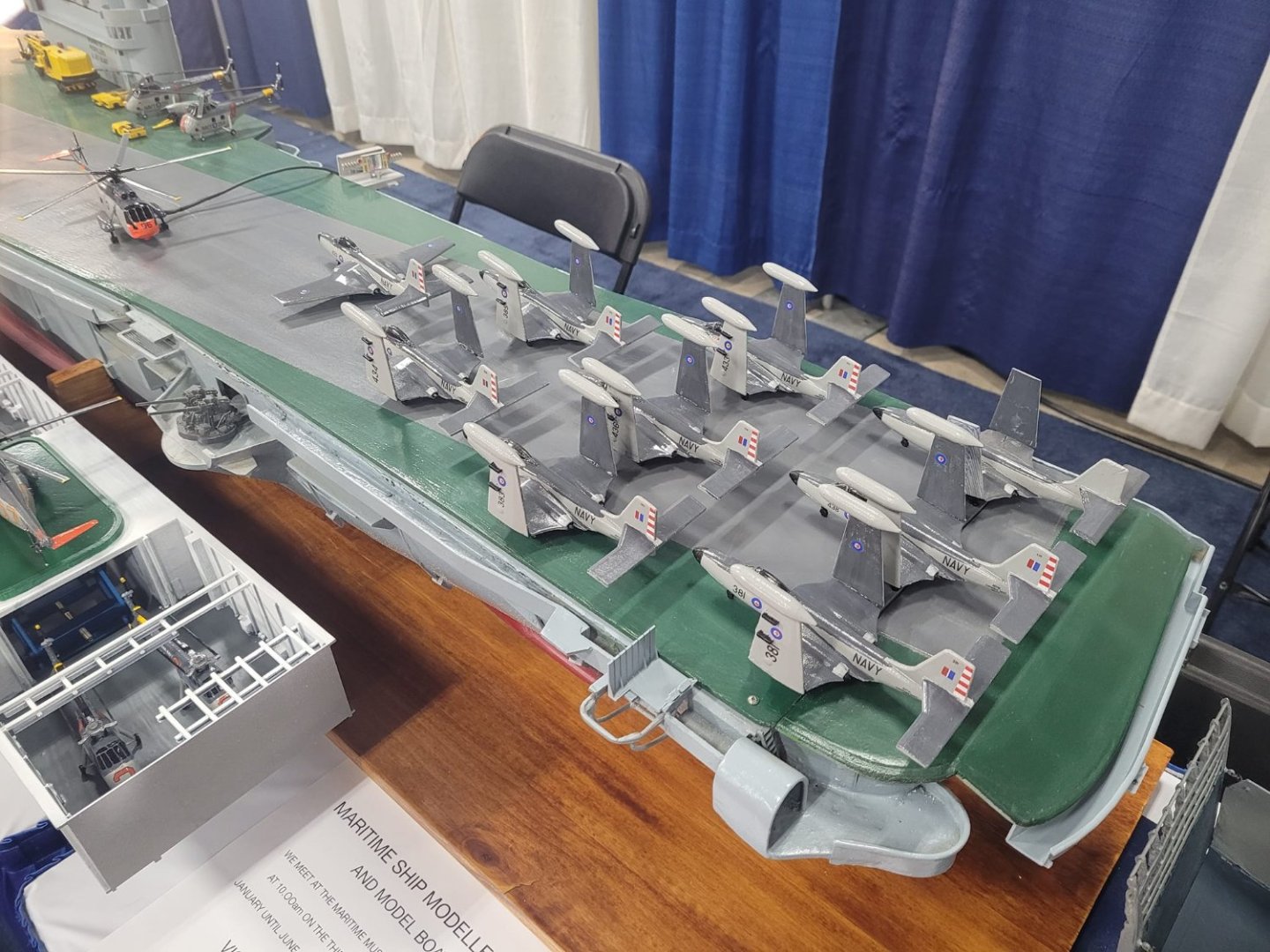
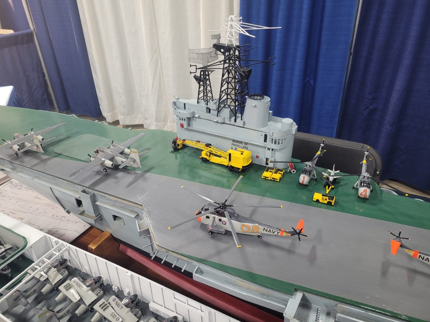
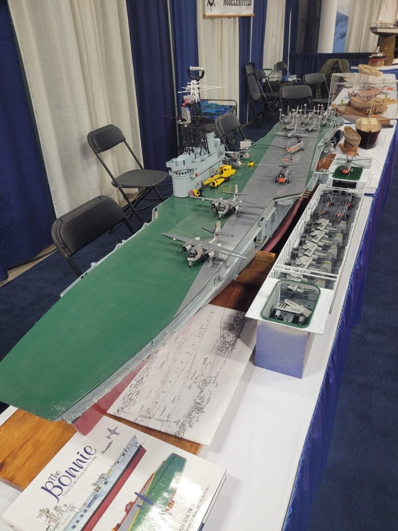
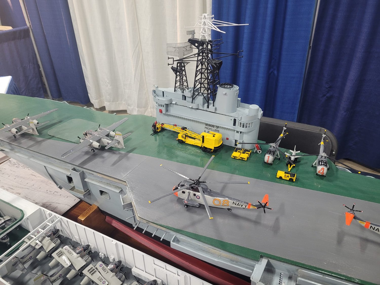
I brought the Bonnie out in her current state to show at the Halifax International Boat Show with some fellow modelers and their ships from the Maritime Ship Modeler's Guild.
If you're in the area, feel free to drop out tomorrow afternoon, Saturday or Sunday!


- Keith Black, Prowler901, AON and 2 others
-
4
-
1
-
That's nice work! Well done!
-
I've got a good start on the plank that I'll be using as the base - a layer of polyurethane applied to both sides of it this evening. I need some more lumber to finish it up - some oak for the supports, and some rails for the bottom edges to add some stiffness and strength.
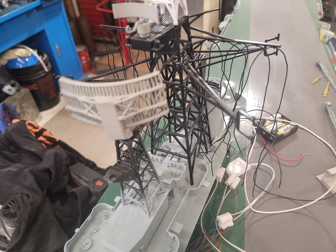
So, while I was waiting for the paint to dry, I decided to have a peek at the mast, and maybe run some of the signal halyards.
Ended up running all 10 of them. I didn't tie them yet, I haven't thought that far ahead, but the lines are run, so that details is about 1/2 done.
I'm not sure how much more rigging I'm going to add - in looking, there's definitely a flag to be hoisted from the mainmast, but I'll have to see where that is to run. This is the first time I've ever actually done rigging on a ship model, so I'm pleased that my initial design actually worked on this!
- yvesvidal, Keith Black, mtaylor and 3 others
-
6


HMCS St Thomas by NavyShooter - FINISHED - Bensworx - 1/48 scale - 3D printed
in - Kit build logs for subjects built from 1901 - Present Day
Posted
Here's a couple more pictures of tonight's progress.
A bit more printing (small boats) plus some more sanding, and the first layer of gel-coat applied. We'll see how well that dries in the garage overnight.