

NavyShooter
-
Posts
438 -
Joined
-
Last visited
Content Type
Profiles
Forums
Gallery
Events
Posts posted by NavyShooter
-
-
OK, had a great visit with 3 veterans who came out, alas, the gent who sailed on the Bonnie wasn't feeling so great and didn't come with the others. The 4 of us had a great time telling old sea stories, and poking about my workshop. A relaxing night.
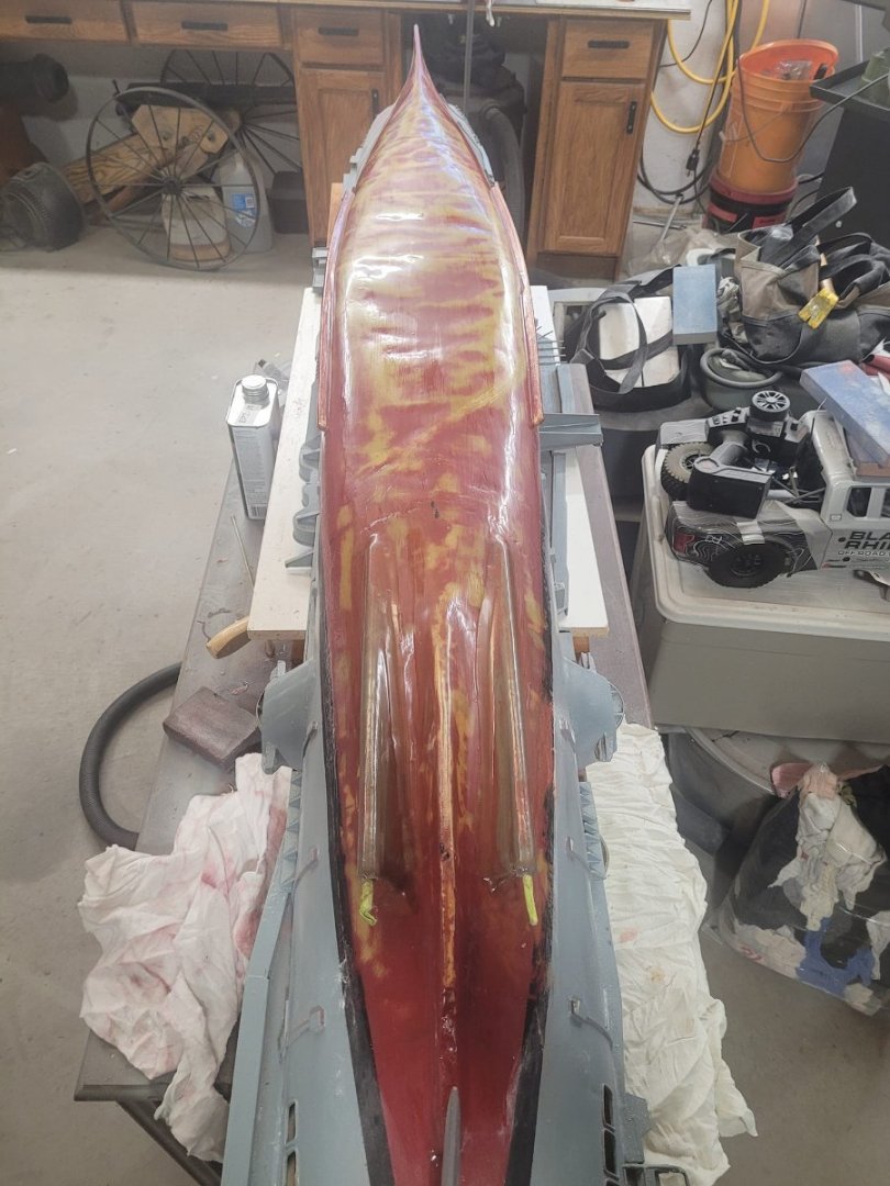
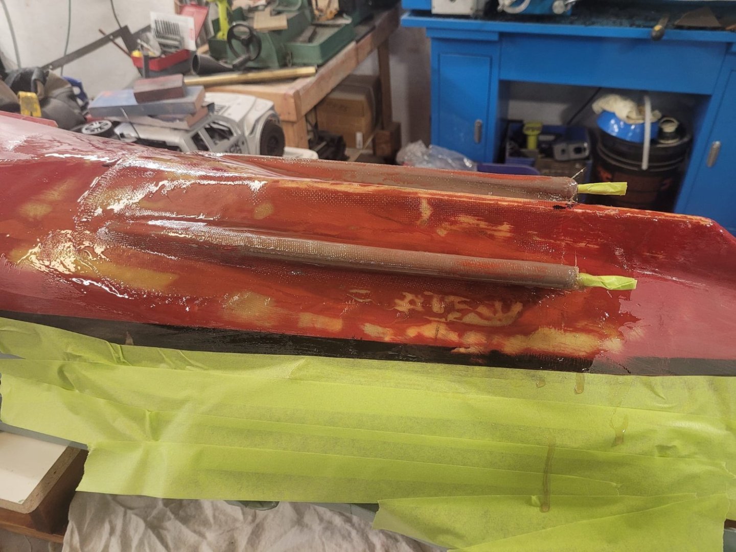
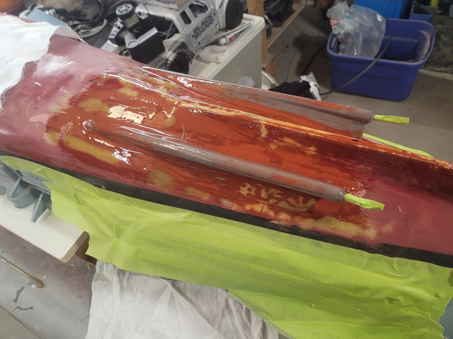
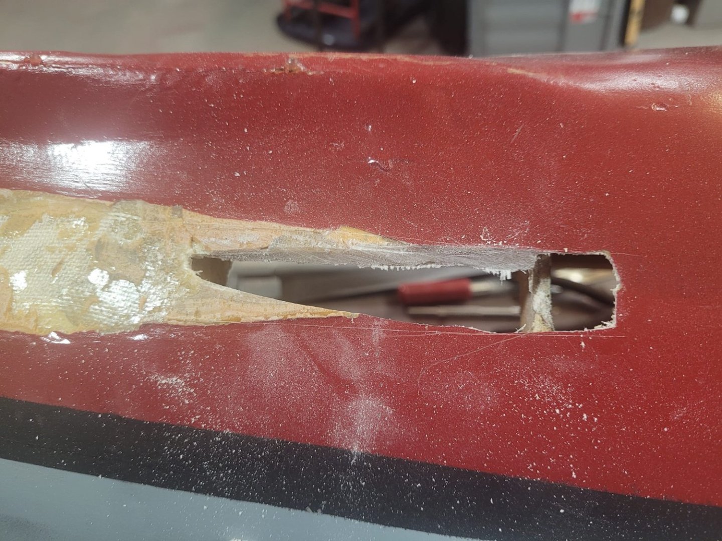
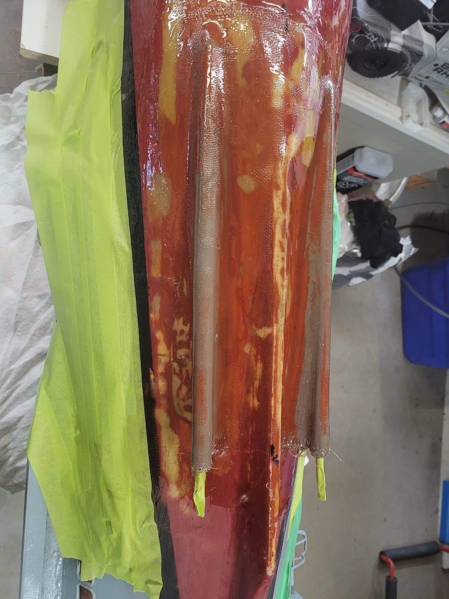
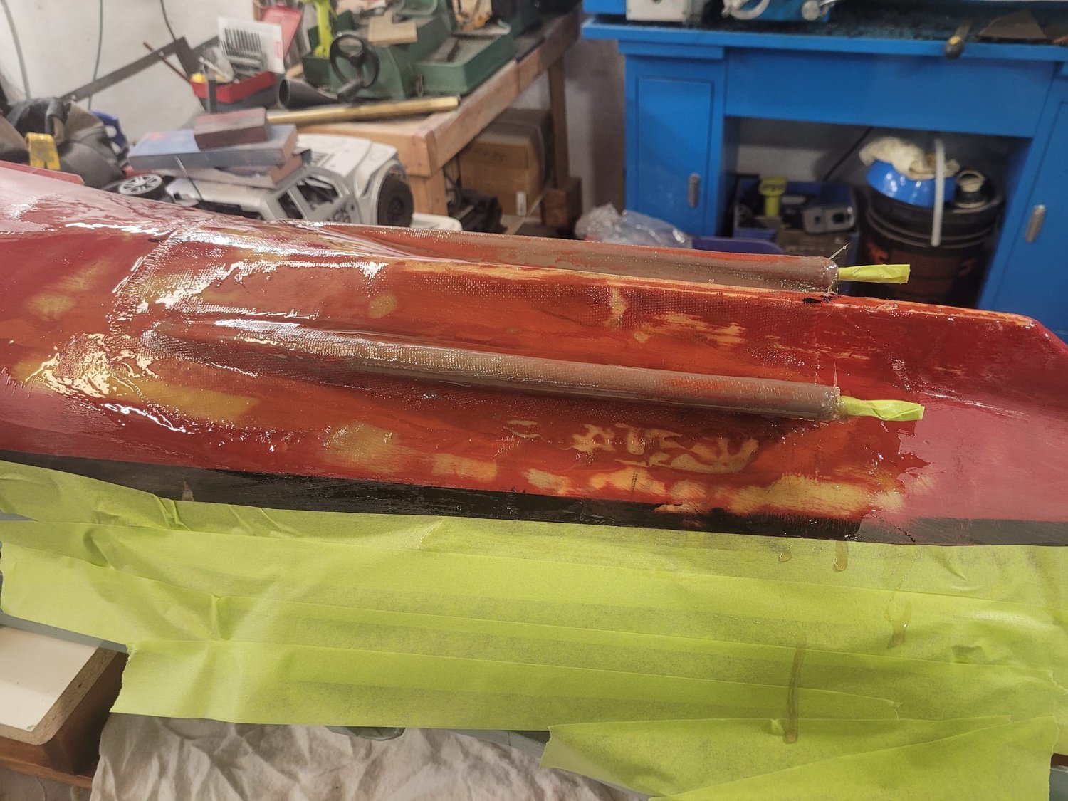
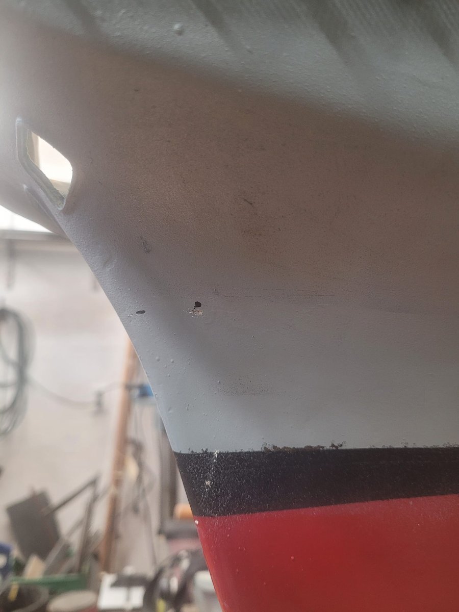
With a hurricane visiting Halifax this weekend, I had some time at home to do some puttering about, and this afternoon I finally started the fiberglass work on the skegs. And the bottom of the hull. I ended up having a look at the keel, and oh my, there was a bit of a mess that I really hadn't appreciated before. So. Solution is a couple layers of fiberglass with a bit of sanding between.
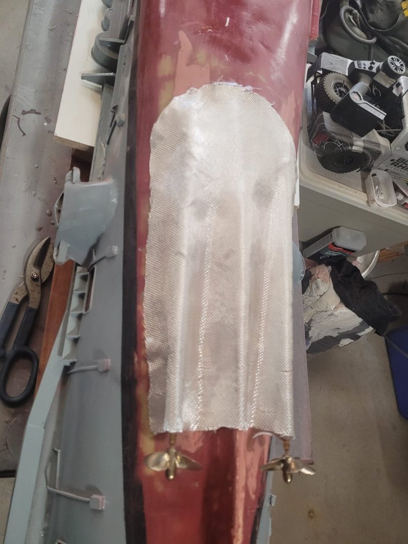
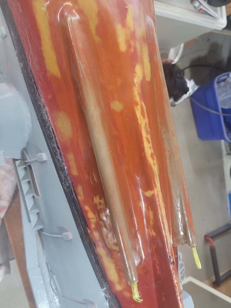
The skegs got a layer of cloth added, and several layers of resin. (Got 4 layers down this evening.)
Here's some photos:
In the beginning....
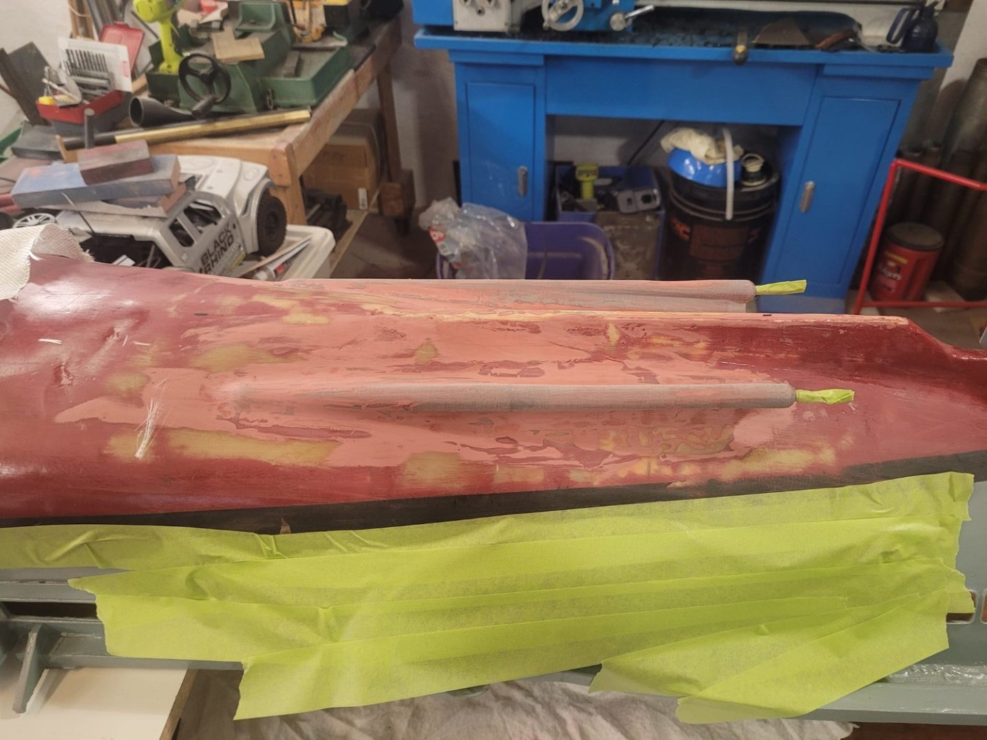
The Cloth.
The end - after 4 layers.

-
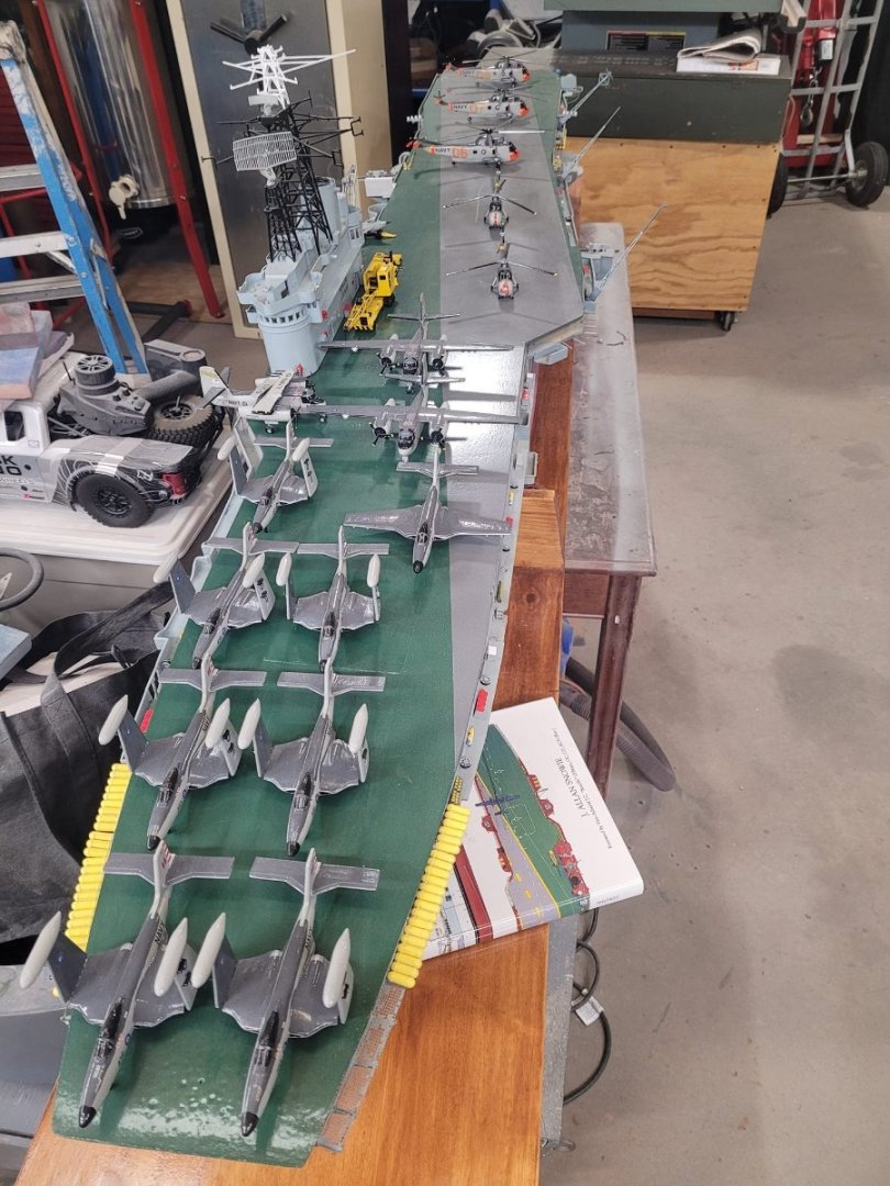
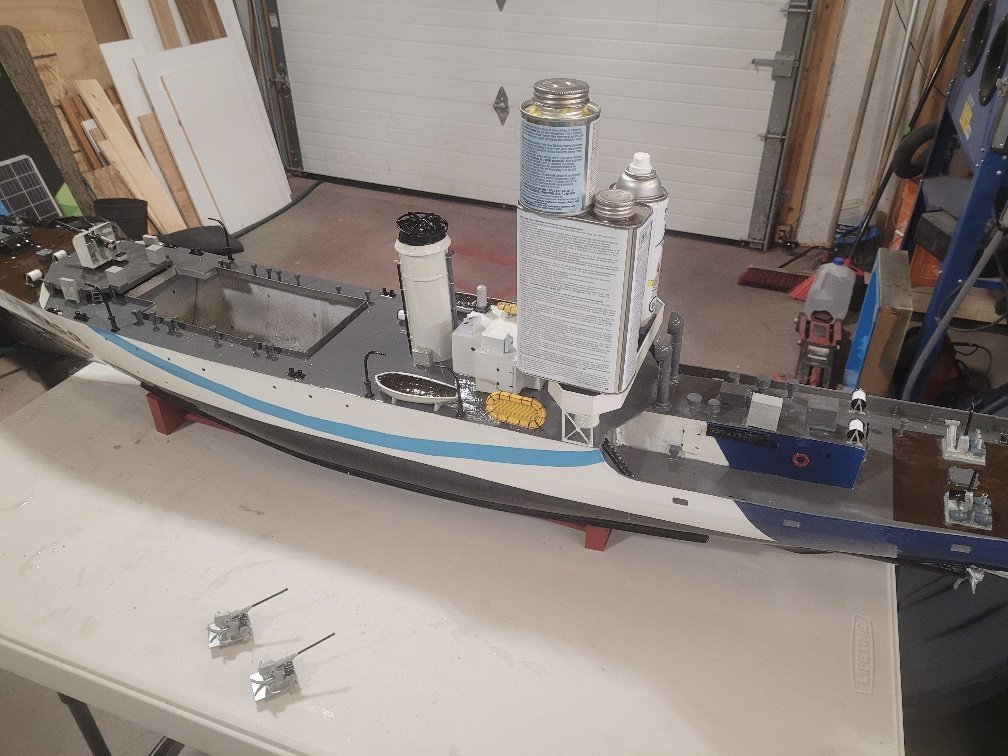
I've got some Veterans dropping over on Wednesday evening to have a look at the Bonnie...including a couple who sailed on her back in the 60s.
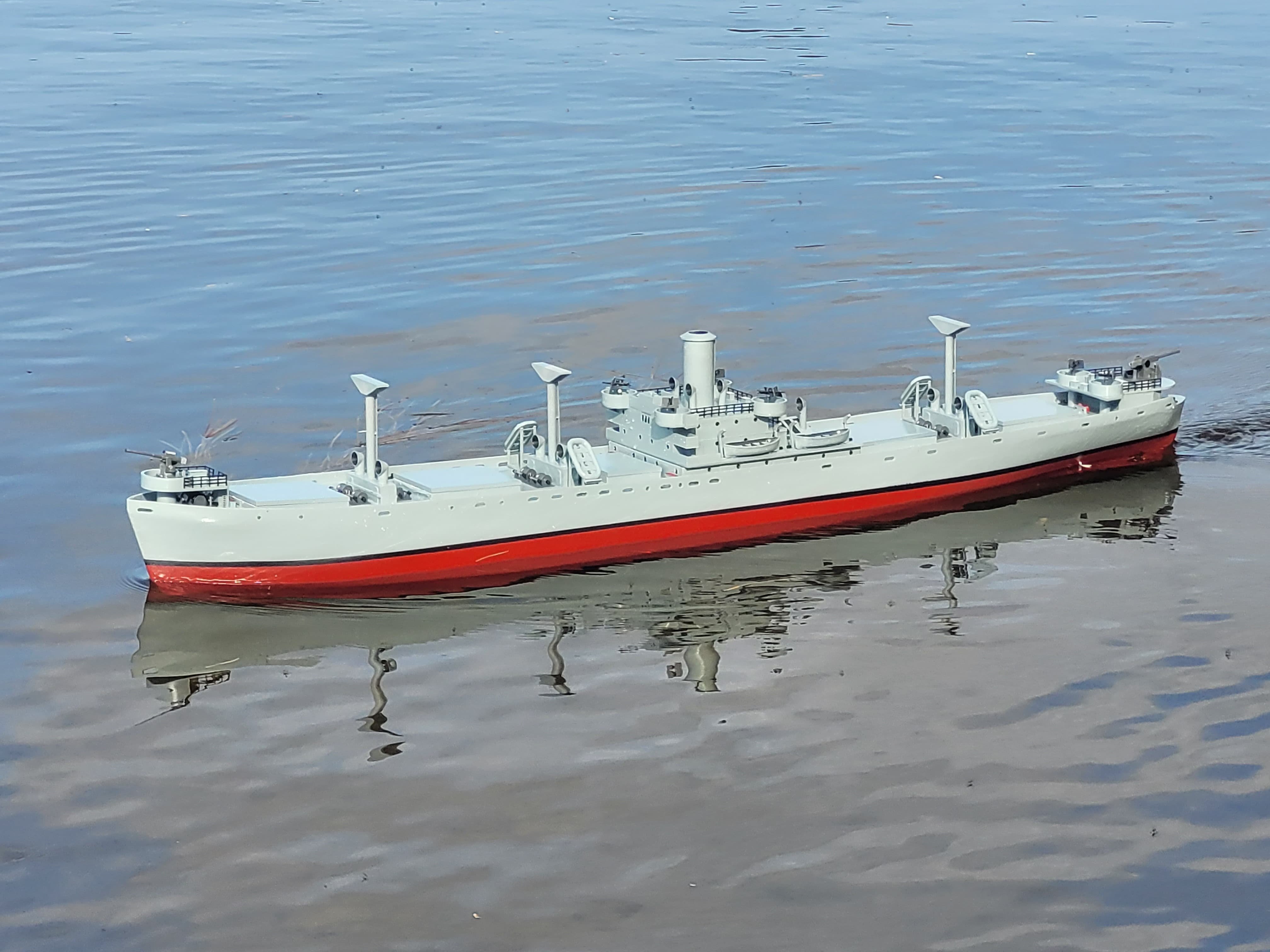
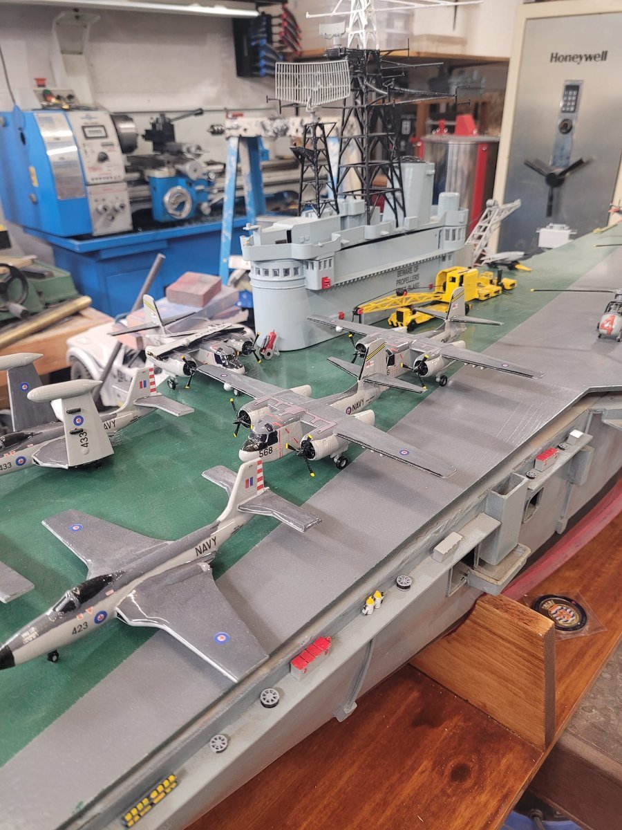
So, I set aside the work on the shaft lines, did some tidying, and dressed her up to show her off.
Here's how she looks tonight:

-
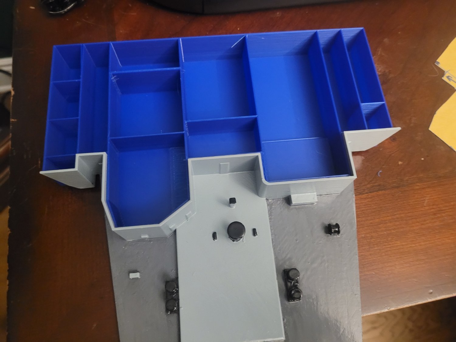
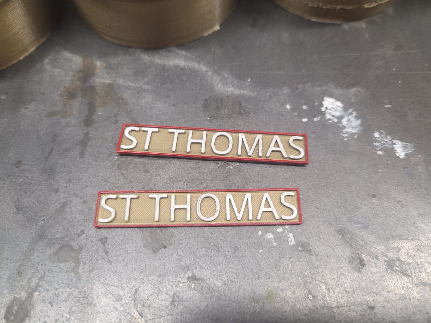
Great thing about 3D printing is that if things ain't quite right, you can modify and pop out a new part in just a few hours.
Here's where we are at tonight...version 4 seems to be about right.
- yvesvidal, mtaylor, Keith Black and 2 others
-
 5
5
-
Alrighty....and I discovered that I'm sometimes a bit of a dummy...
I took the printed part out to the shop and tried to test fit it...and couldn't get it into the hull. Too wide. Of course. The overhead frame did not allow it to sit in...so now it's chopped into smaller sections and we'll see how that looks tomorrow.
And I fixed a few minor points of alignment in the model...
- Keith Black, mtaylor and Canute
-
3
-
-
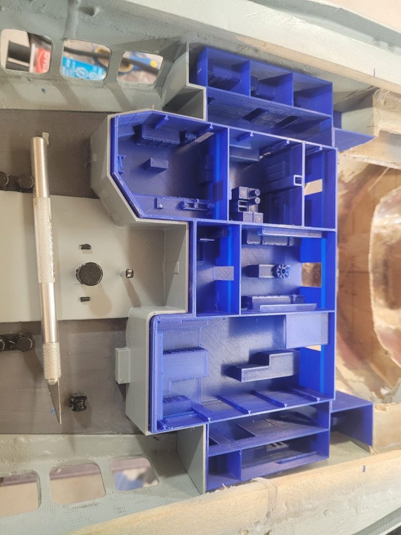
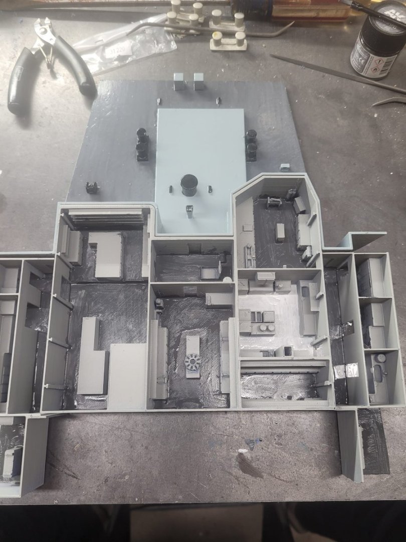
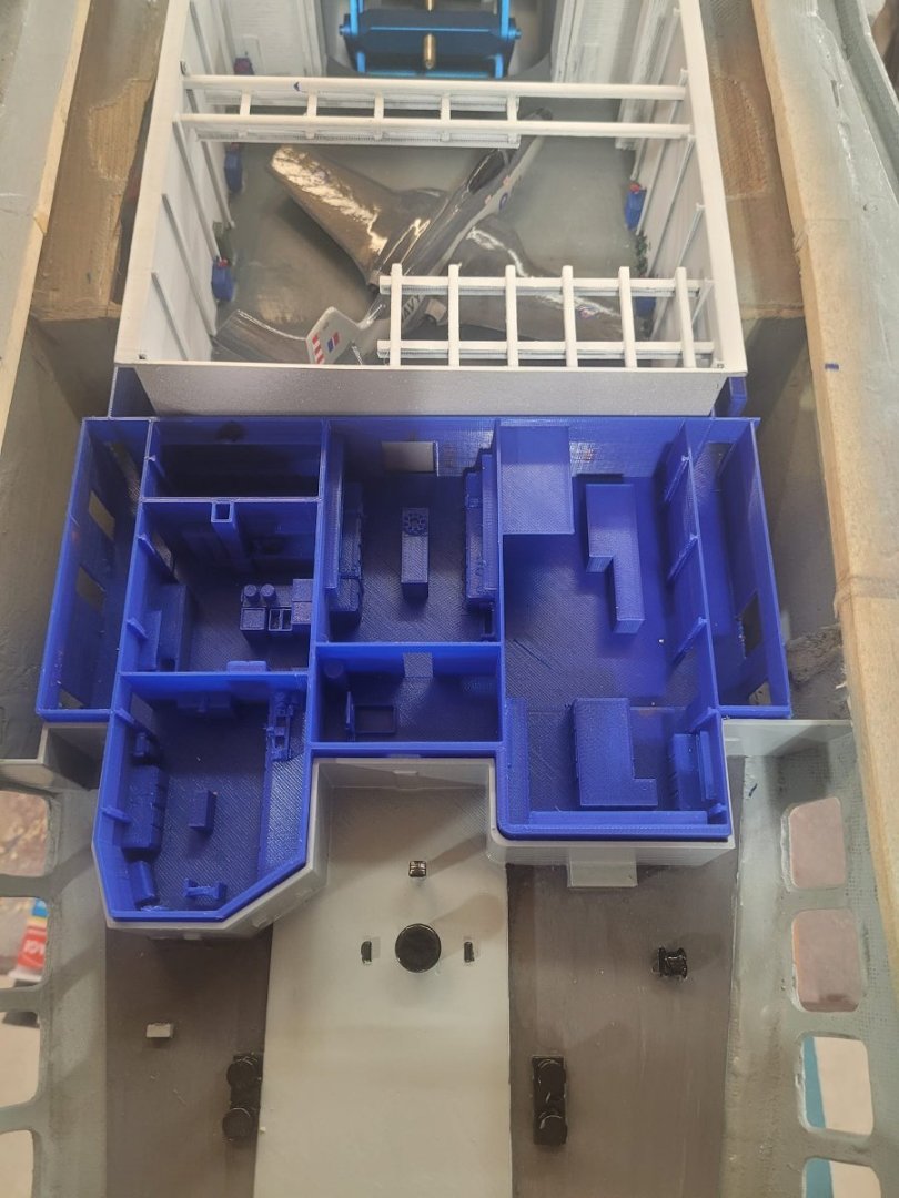
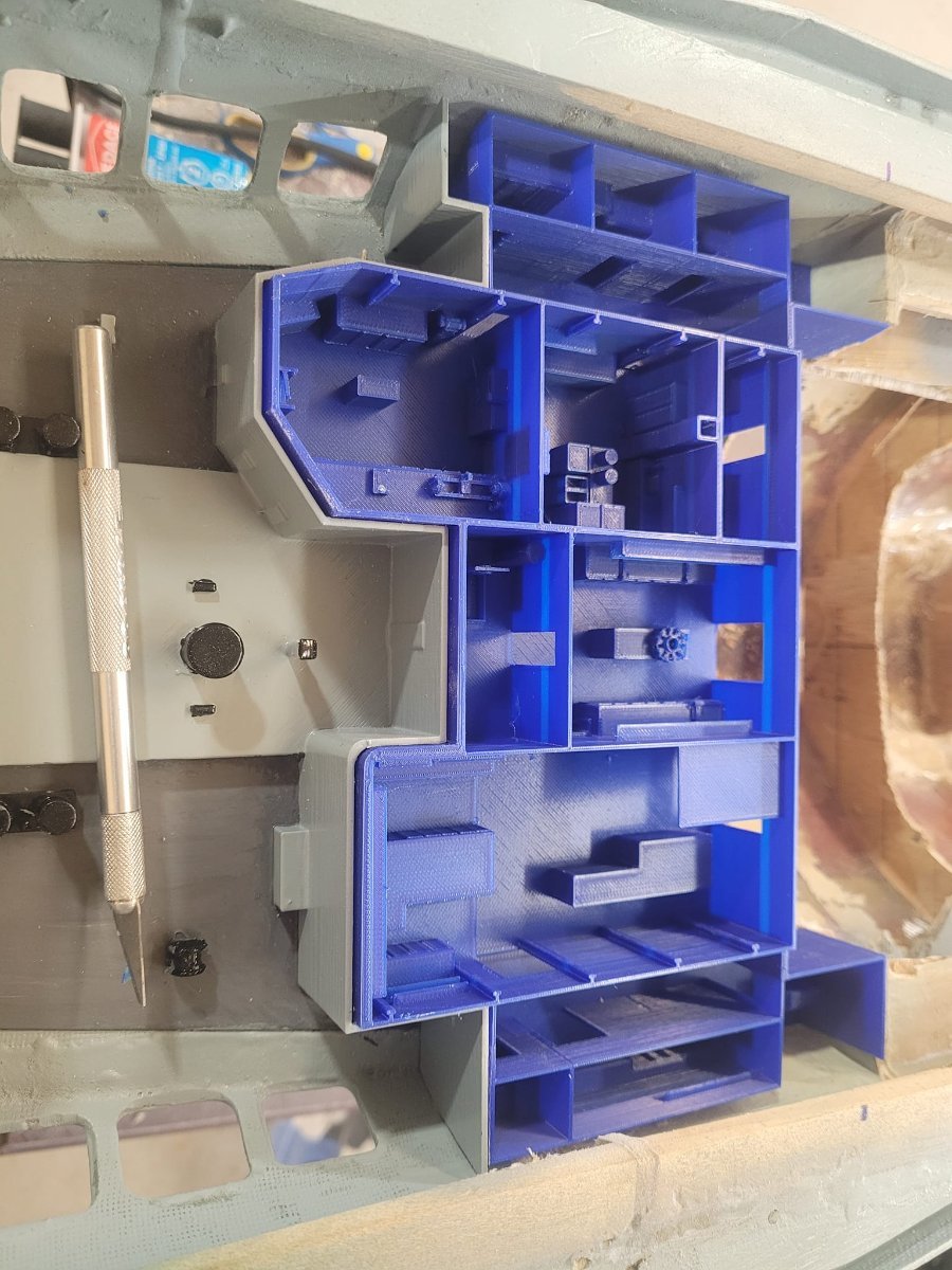
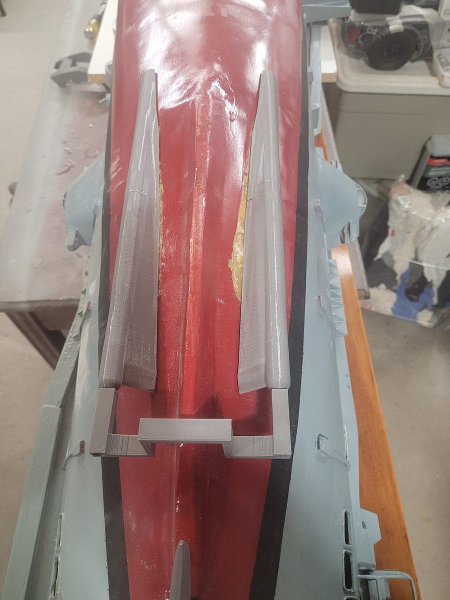
So....in looking at the photos above, I realized that there was a gap that bothered me. That being the gap astern of the aft hangar bay. When the flight deck panel for the aft hangar bay is open, it will let this space be seen, and I'm not a fan of this big ugly gap...so what to do about that?
I stepped back to the plans, and pondered things.
See the plan view with the red highlights....That's what I'm going to build to fill the gap.
Some 3D design wizardry and 4 hours of printing, and presto...I have the 'sample' to test fit and adjust ready to pop into the hull tonight. There WILL be changes necessary to this, however, the most important part of fitting in with the already printed cable deck section was key.
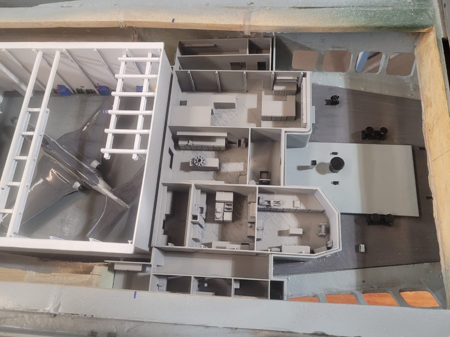
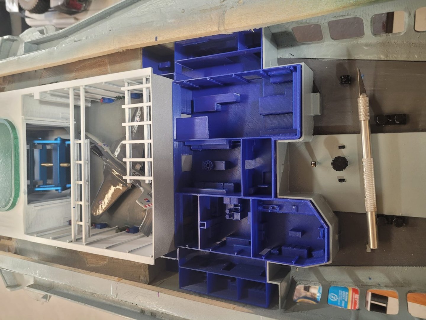
It fits as can be seen in image 3. Which is a good thing.
I've already started doing some detail-work on the interior spaces - there is a selection of workshops and the wardroom galley space in here, so I'm going to have fun designing and printing some of these bits. We'll see how it all looks in the end!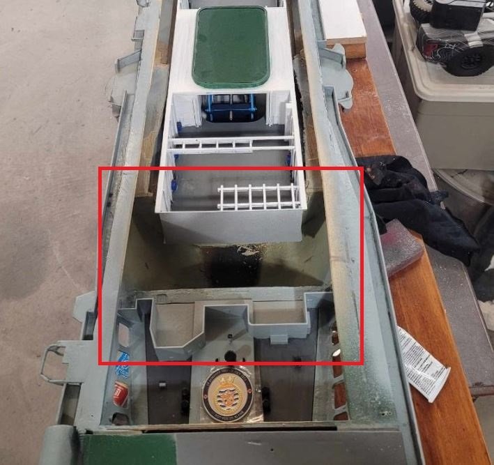


-
-
Nice job on the casings - a question though - some Russian systems used lacquered steel (green-ish) casings. Was this the case for the 85mm? Or were they brass? (mid-war brass shortages were a thing.)
As for hurricanes, I grew up in a house with a leaky basement, so I only every bought houses on hills...water would have to come up over 20 feet from the lake to get to my basement level in my current home. I've got 2 generators, lots of gas, sufficient food, and other 'stores' that would be useful. After living through a few hurricanes now here in Halifax, I'm reasonably well setup. I go out with my chainsaw to help others now, and usually lend out the smaller generator to a neighbour that ain't got much, and certainly cannot afford to lose a freezer worth of food.
-
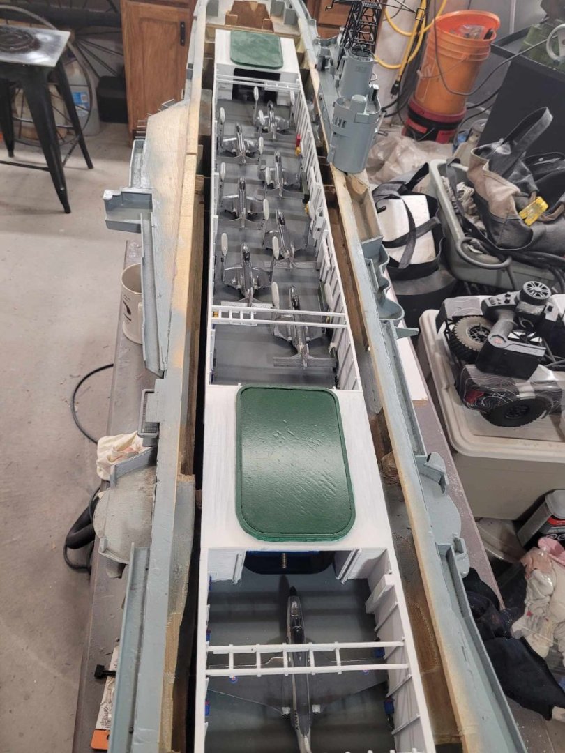
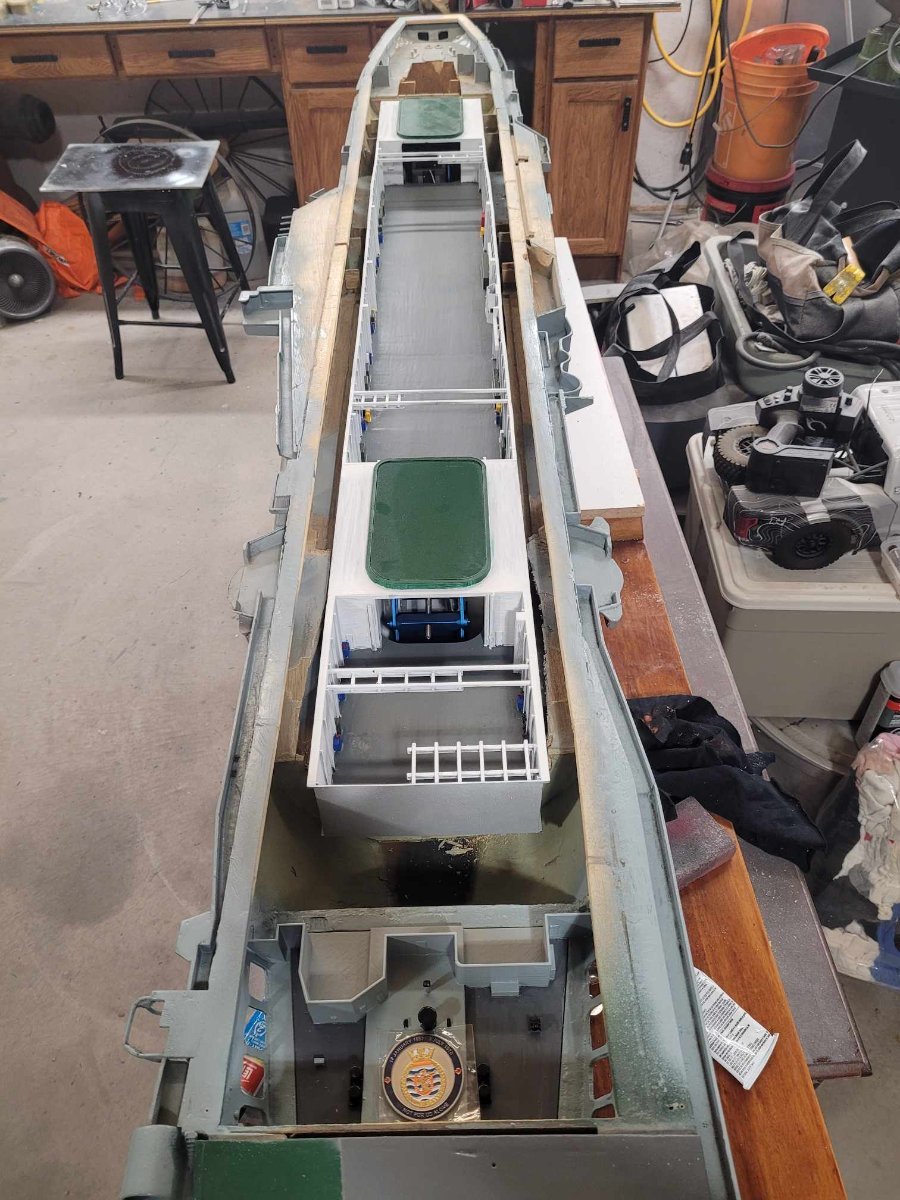
So, as I waited for the epoxy to dry so that I can sand down the protruding bits, I decided to have a look at how things are going together...and so I set the hangar deck into the hull. With the new motor mount in place, I wanted to make sure I had clearance below the hangar (which I do!) Then I looked at things a bit harder, and realized that I still had to cut a couple of inner frames down by a bit to fit the hangar fully into the hull.
So.
Out came the razor saw, and off I went, having marked the frames. 5 minutes later, the hangar deck is now resting flush with the flight deck, where it belongs!
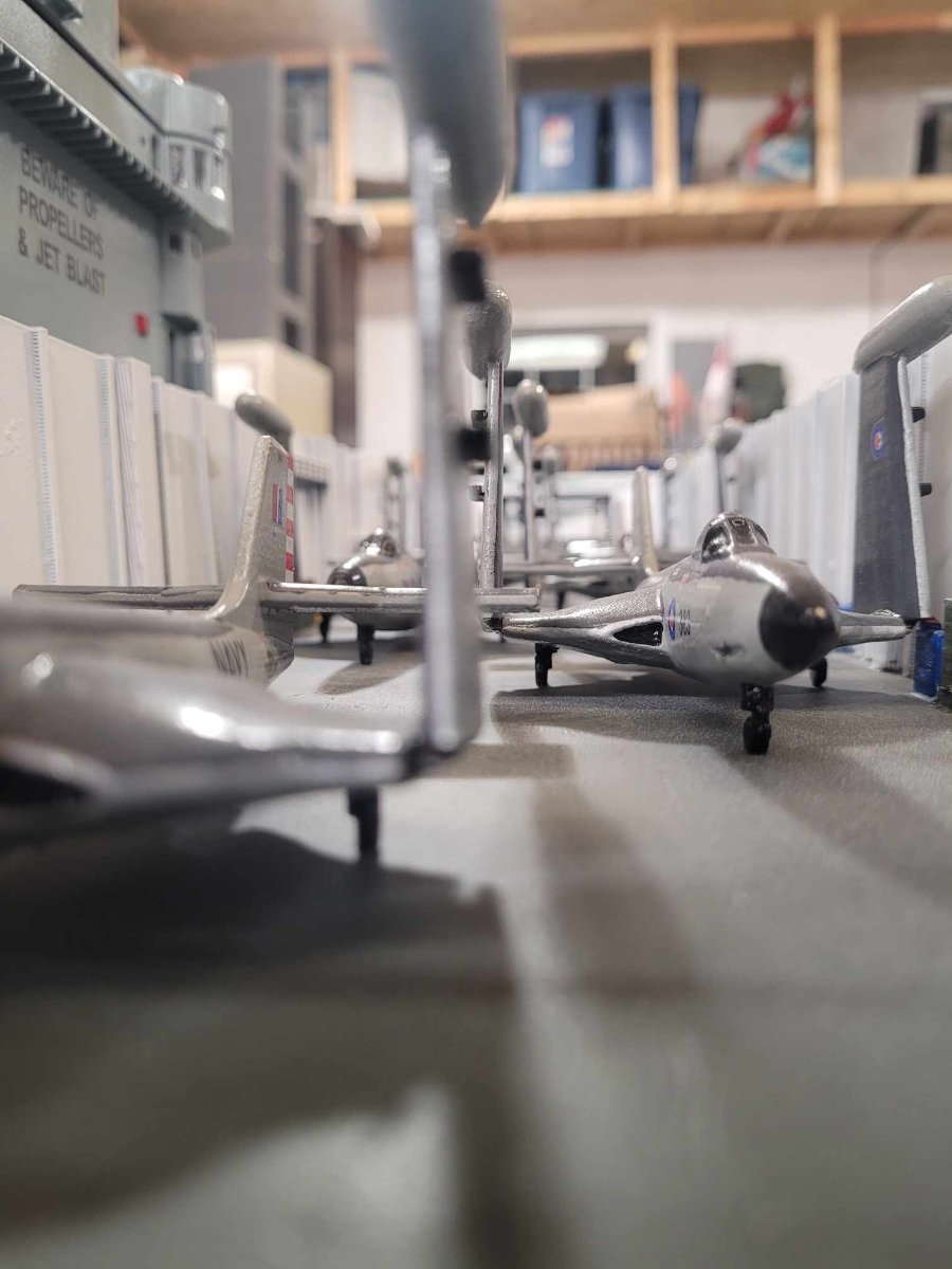
I put the island on to check clearances, as the plan is to have the island fixed in place, and be able to remove the hangar deck when necessary without removing the island. All of the 'major' electronics will be along the keel, below the hangar deck.
So...this was the first time I'd had a chance to fit it all up, and by thunderin', she fits!
Here's a few more photos for your viewing pleasure. I decided to stick some Banshees into the Hangar for the last couple of photos.


- Keith Black, Canute, mtaylor and 2 others
-
5
-
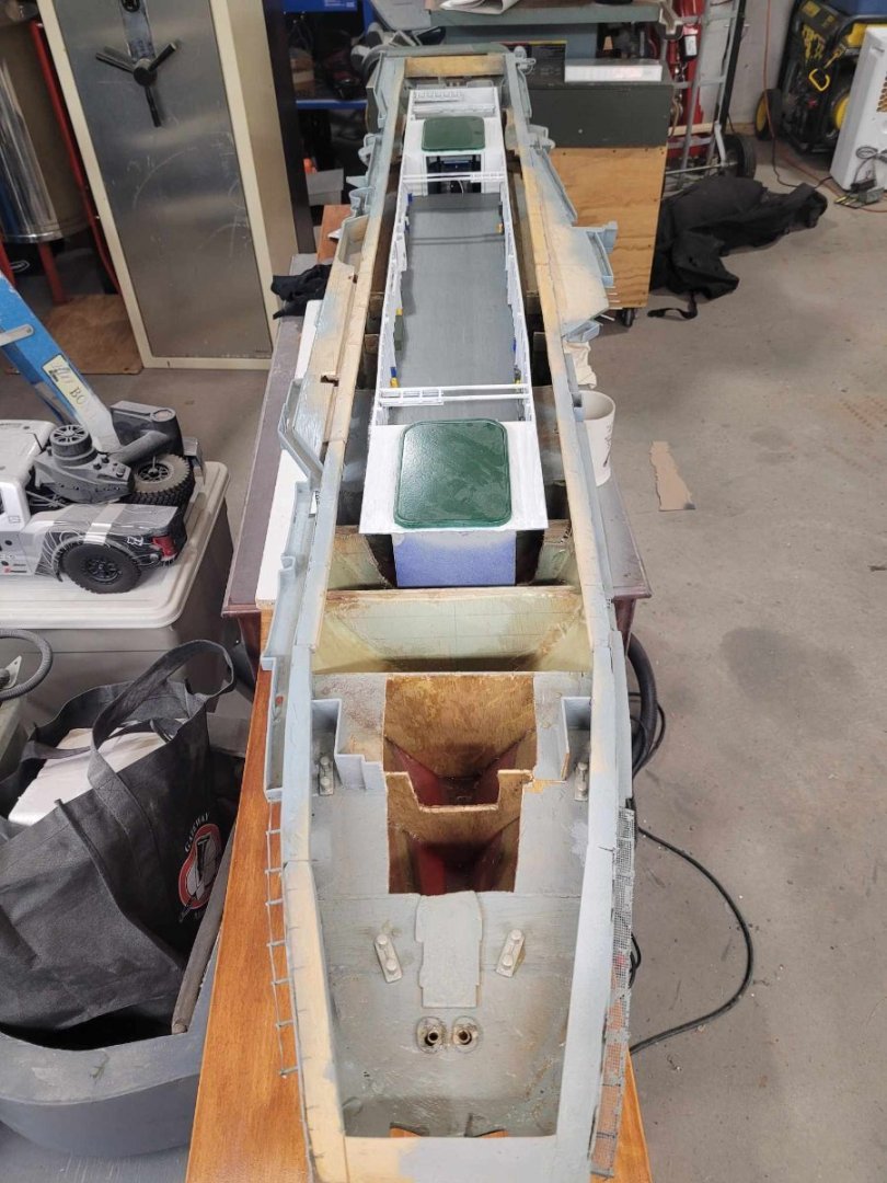
OK, after a second application of epoxy, I have 'adjusted fires' to putting on some putty. Once the putty dries, I'll be sanding it, then putting a layer of fiberglass overtop to lock everything together.
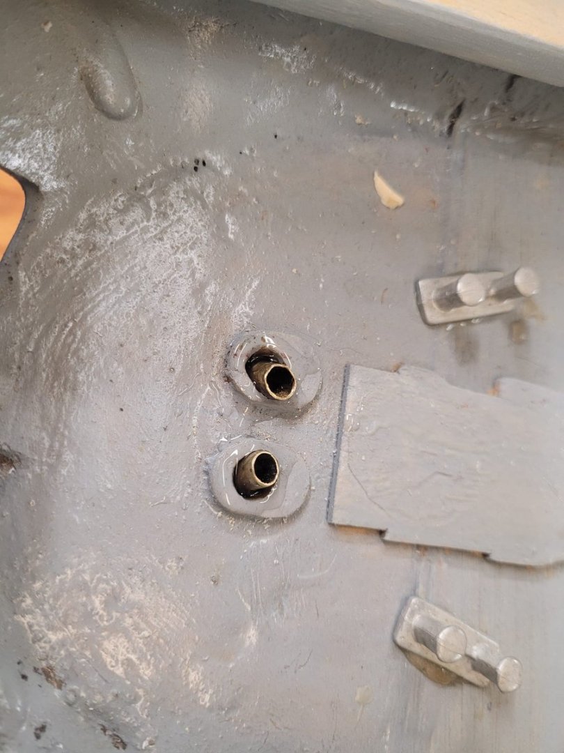
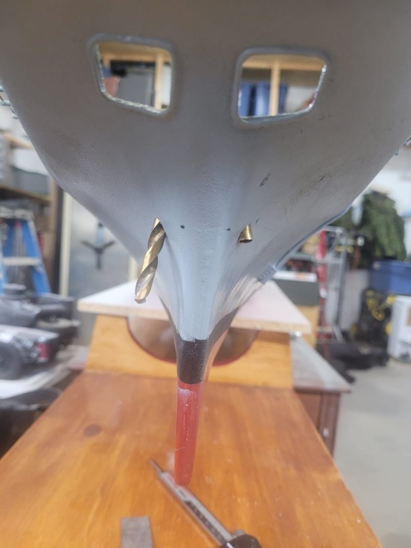
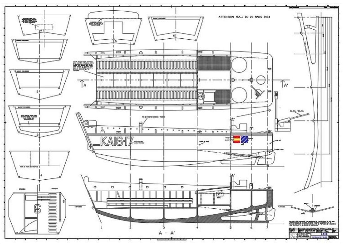
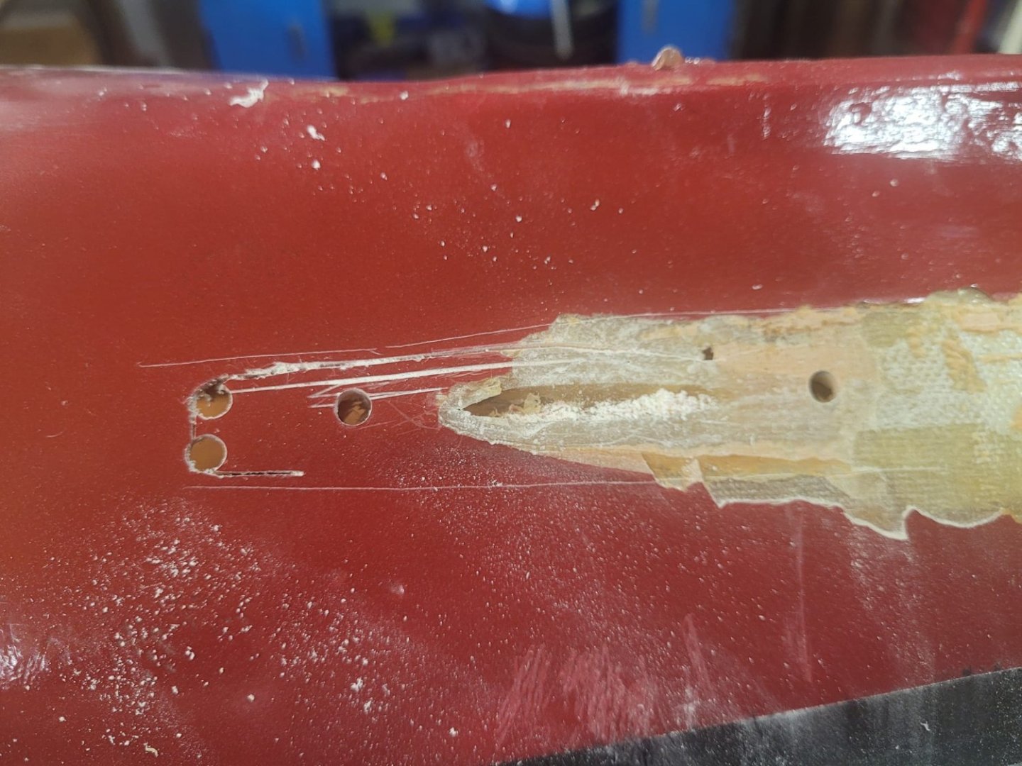
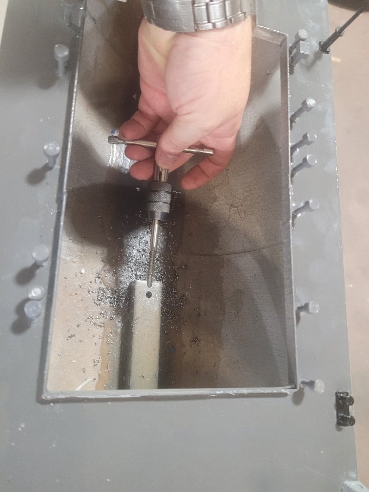
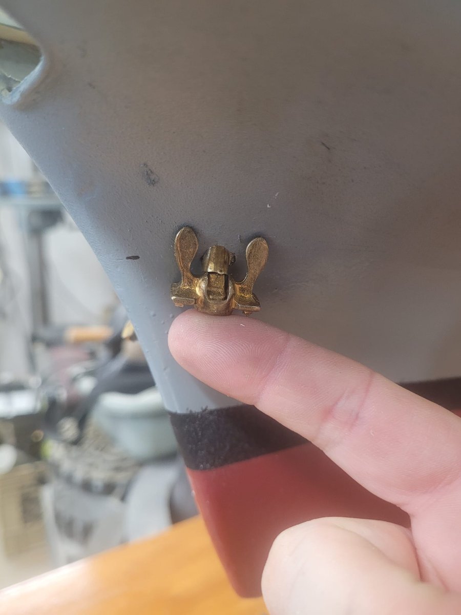
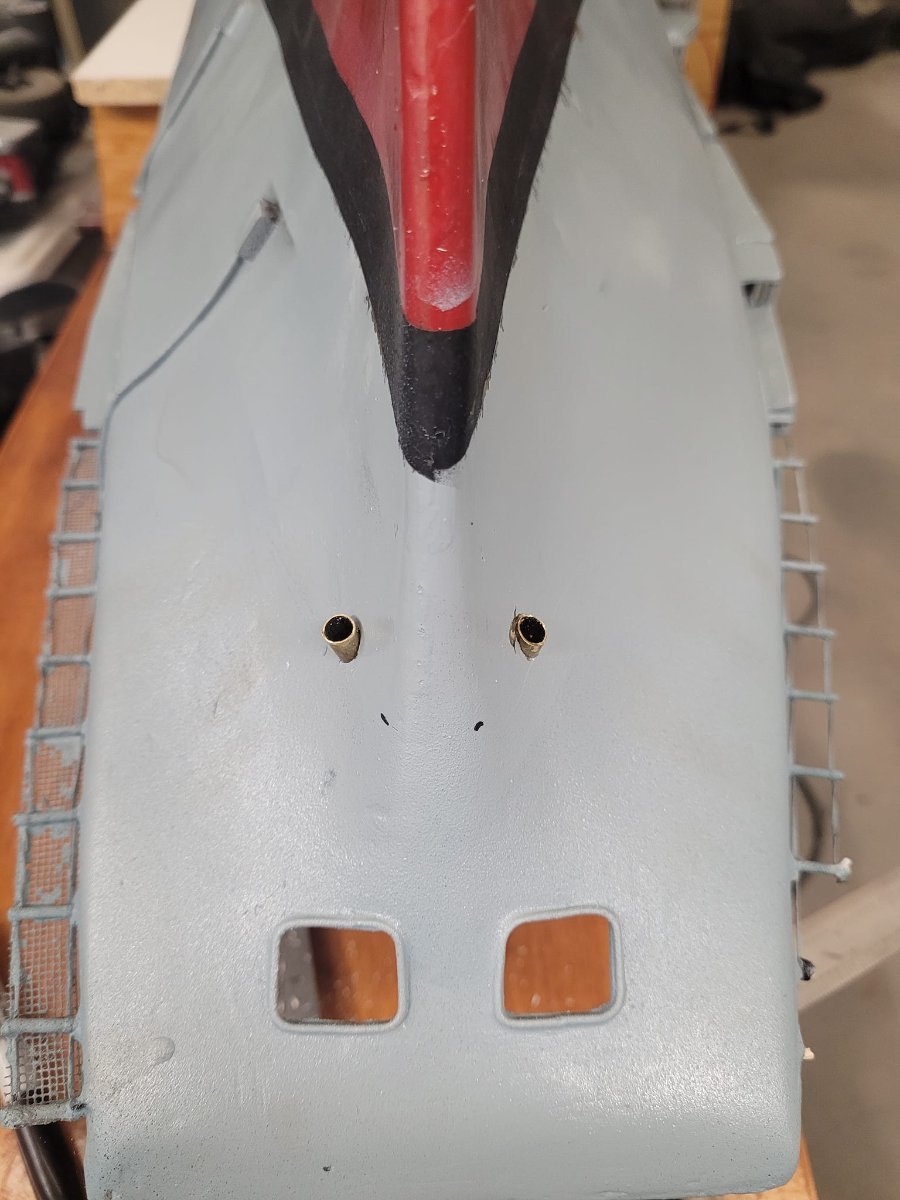
As I wait for things to dry though, I had some time out in the garage to kill...so....I started working on the anchor system. Plan is to have one anchor functional. First challenge was getting the holes drilled - the original builder made a cable deck area, but did not punch holes out the bow, nor put in the hawse pipes.
So. Off to the drawings, got some dimensions, did some measuring, and started drilling some holes. Started small, and worked up to final size of 1/4".
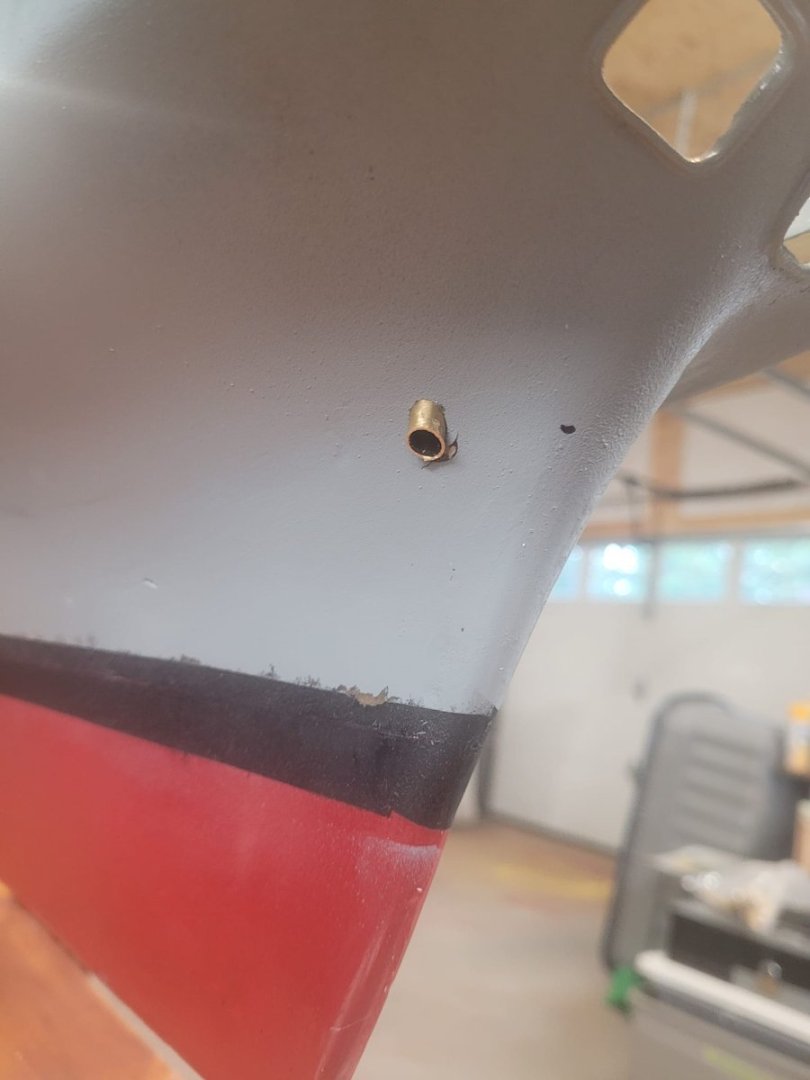
Cut a couple sections of brass tubing to go in as the inserts, which are now in place and epoxied.
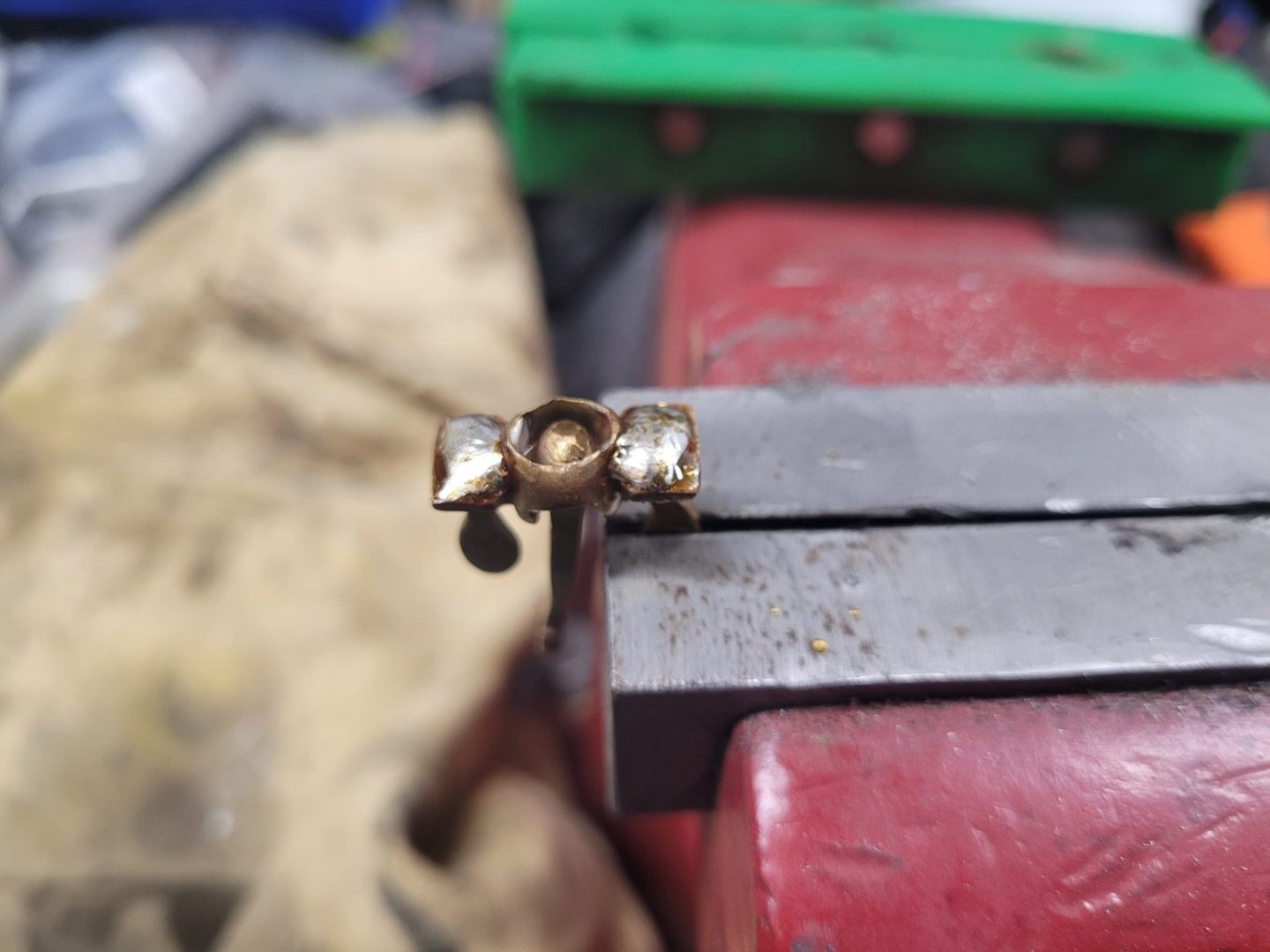
Then I fiddled with the anchor a bit - it's solid brass, but it's light...so I added a bit of 'weight' on the bottom of it - a bit of solder tacked on with a torch. I'm not sure how much difference that'll make, but it shouldn't hurt!
Here's some photos.


-
-
Something to consider is the availability of suitable wood for single piece trucks.
At some point, the trees used that were big enough to provide such massive single pieces of wood stopped being commonplace, and started being rare.
Mostly because they'd been used to make ships, and parts for ships.
NS
- BLACK VIKING, Keith Black, mtaylor and 1 other
-
4
-
Here's a starting point for you.
You would have to scale these up and print them to the proper dimension to use as a reference.
- tom q vaxy and mtaylor
-
2
-
-
1 hour ago, Ian B said:
ooooooooooooooooo doing that would frighten me to death 😱
You should have seen me going at her with the chisel to get the old Skegs off....that was scary.
It is, however, necessary.
The old skegs were unsupported at the ends, the props unbalanced, and the shafts were not sealed.
I could have tried adding A-frames, but that would not have been correct for scale, and would still not have rectified the not-sealed shafts that leaked.
NS
-
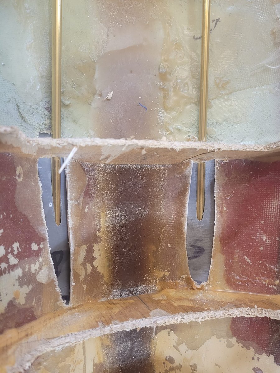
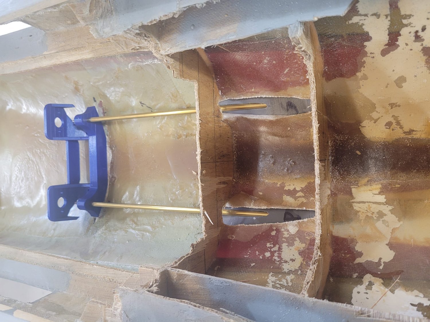
OK, so here we go....I did a test fit with the shafts and the alignment block and motor mount block, and observed the rather poor fit.
So.
30 minutes with a drill and a razor saw later, we have some nice open holes that the shafts will float freely in. Now I can simply align the blocks on each end and then do some epoxy work.

- lmagna, Keith Black, mtaylor and 4 others
-
7
-
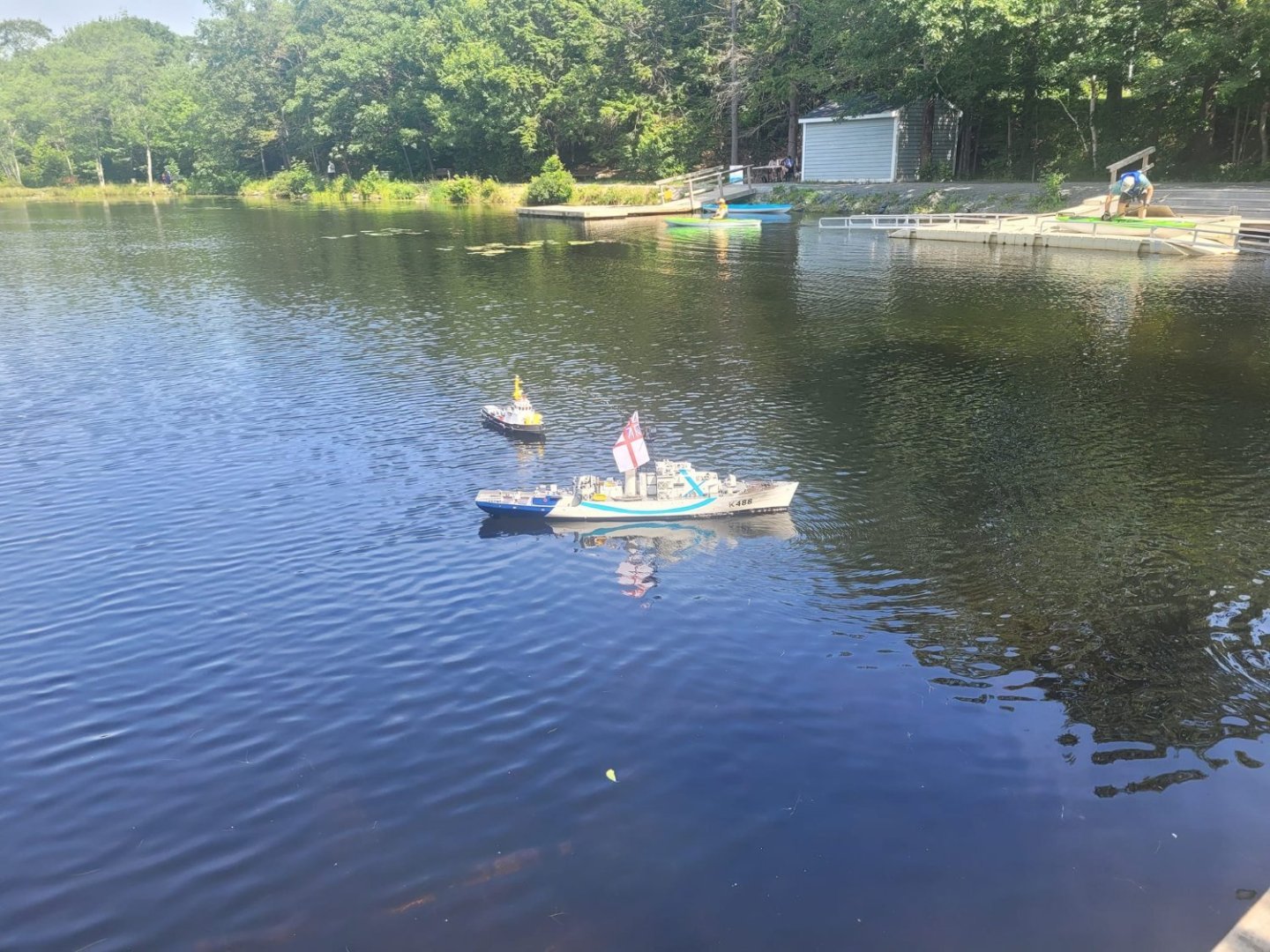
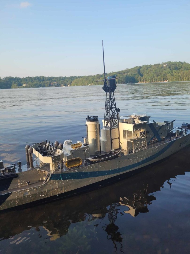
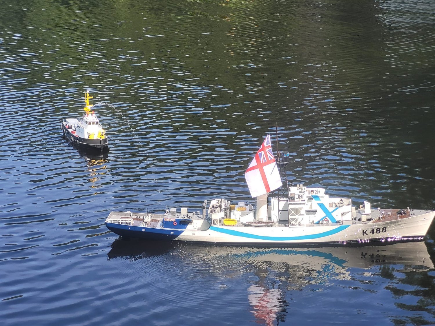
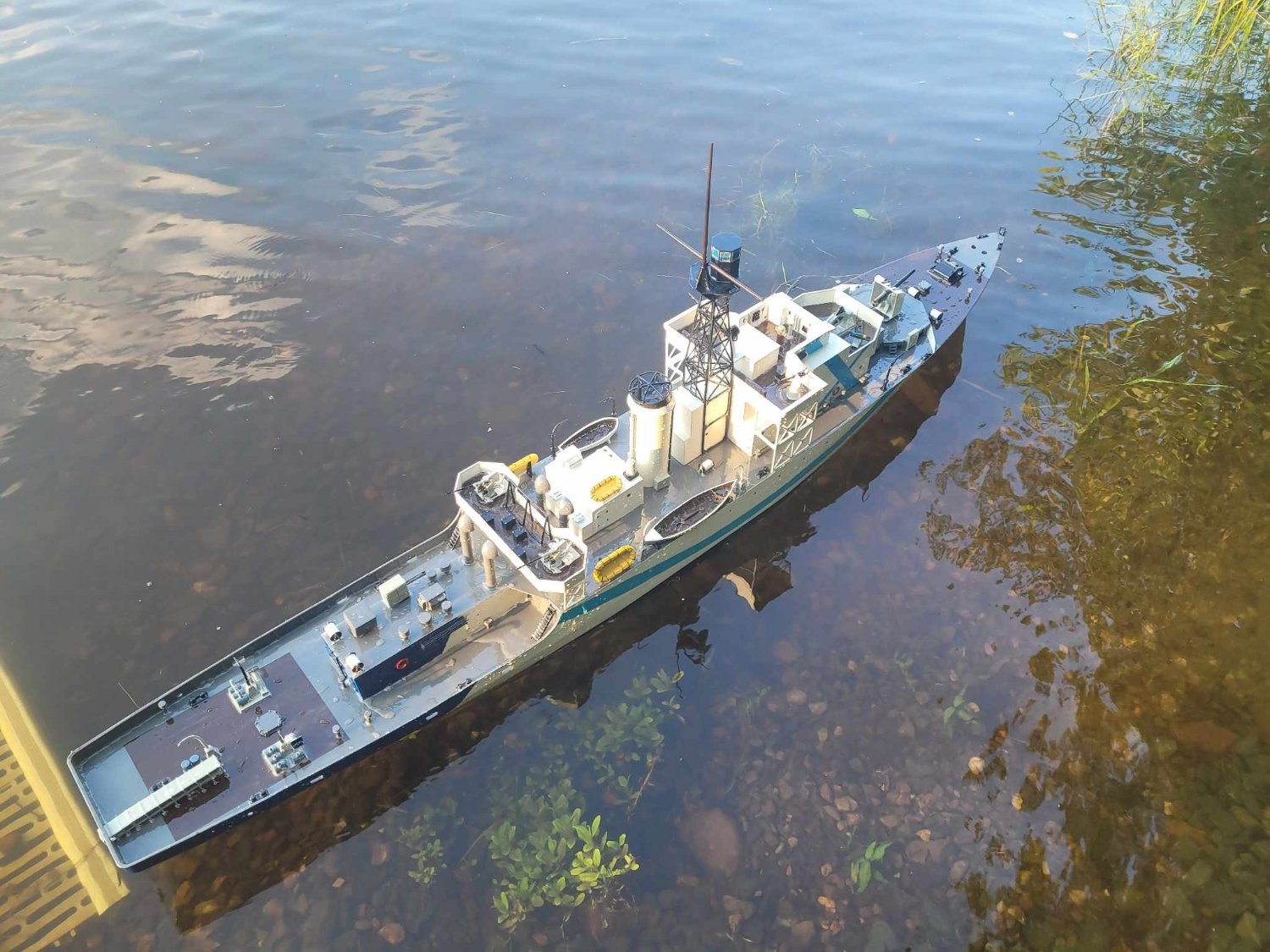
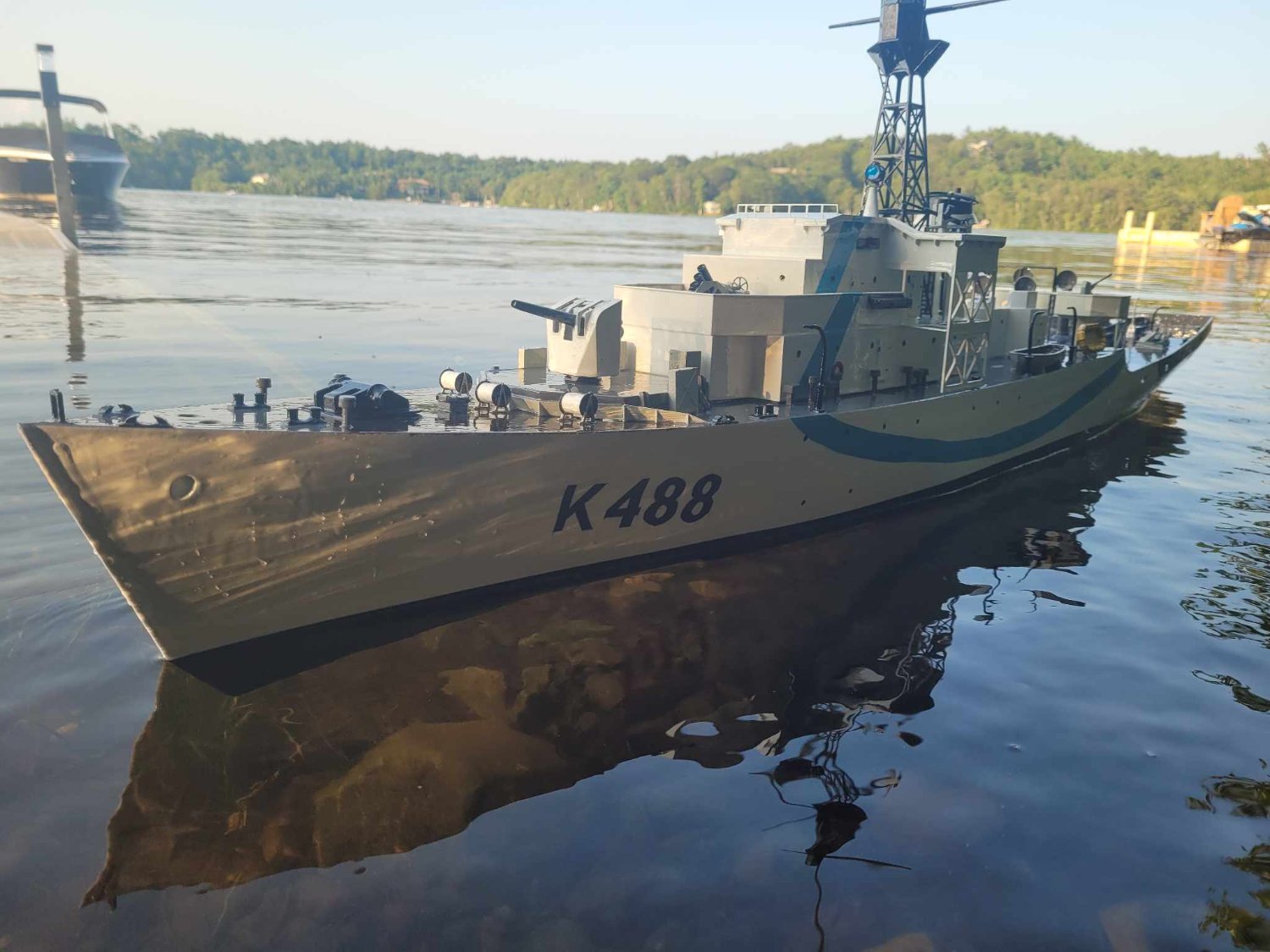
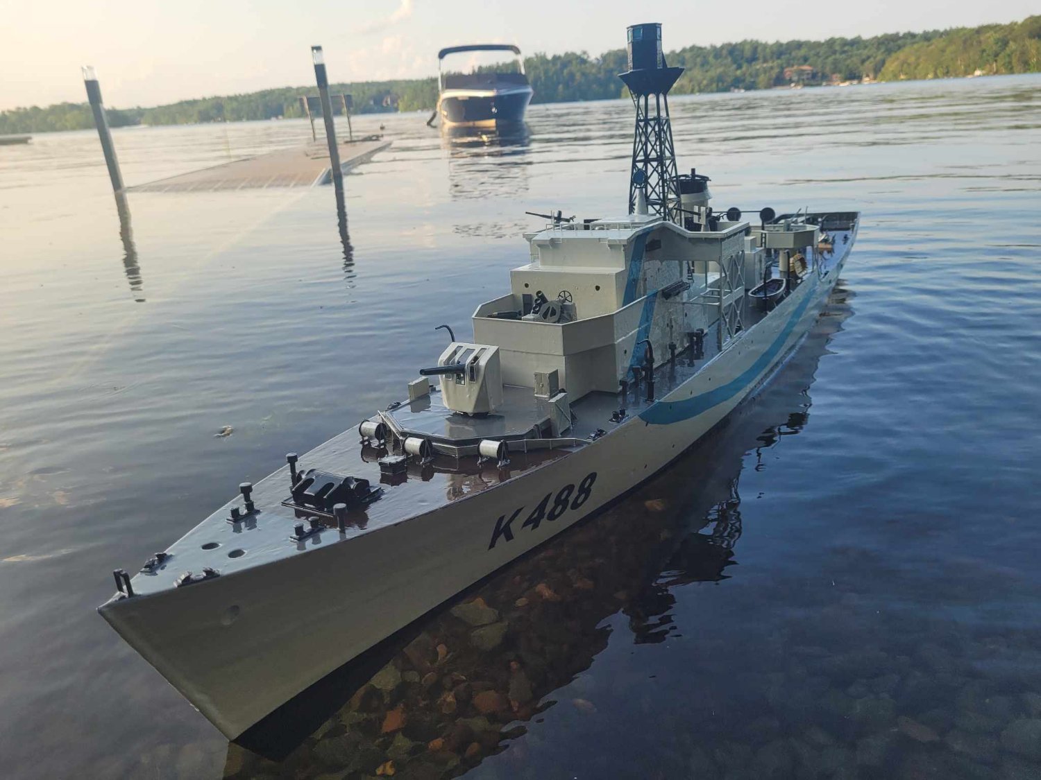
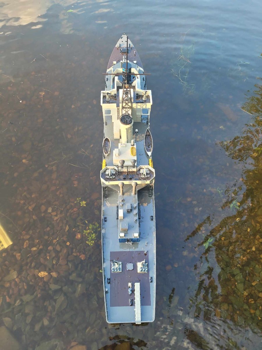
And....the official launch has happened as well. We used a tug to push her out into the pond, then the tug 'christened' the ship with her water monitor.
Some photos from our Guild "Fun Float" yesterday morning.
Yes, I realize that the flag is far from the right scale size, but I felt it was suitable as a 'battle ensign'.... it gets the message across!


-
-
Really well done!
I was out in Edmonton the other week, and came across their local Aviation Museum, wherein they had a Mossie, and had it setup in a 'full scale' diorama, with a ground layout, a start cart, a bomb cart, tools, etc. It was reminiscent of your display!
Great work! -
-
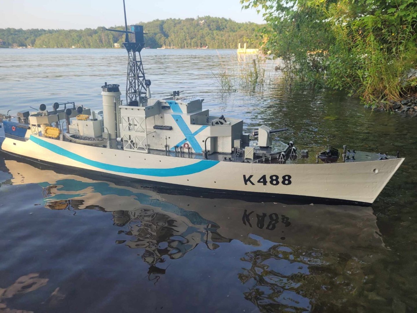
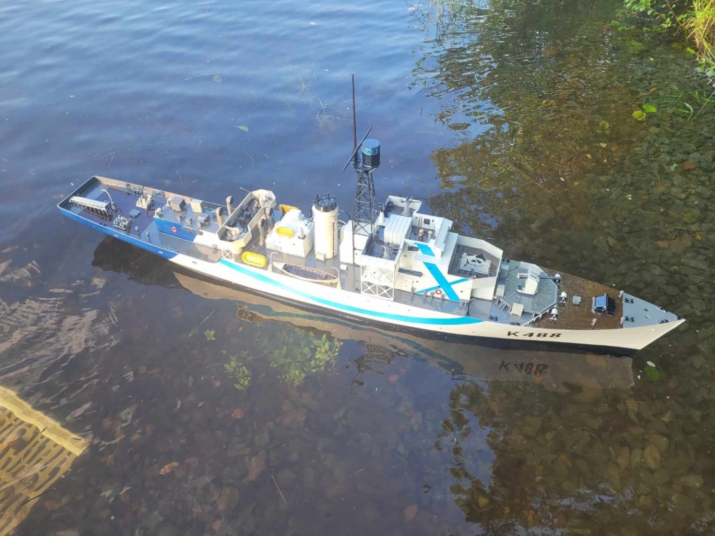
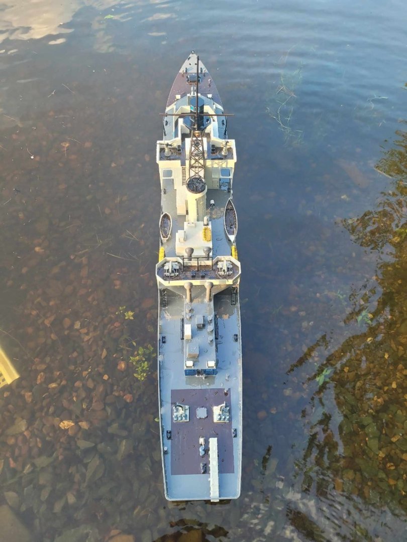
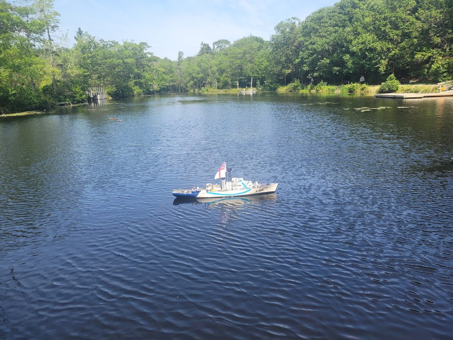
And, we have a successful float test! I shifted some of the ballast around between these photos - the first picture is the final ballast positioning. I took almost 4 pounds out from where I started.
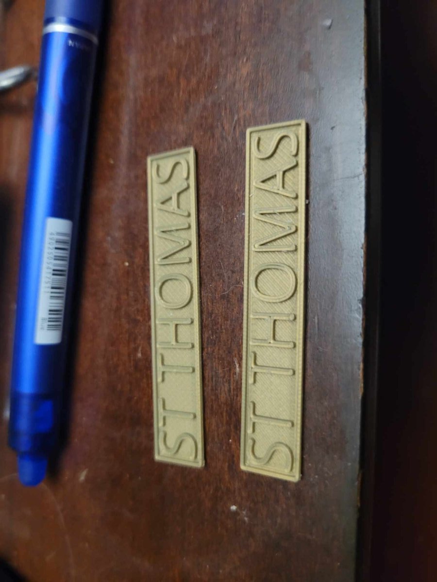
She's back in the garage for two final touches - name plate and a flag.
On Saturday, we've got a fun float with the model ship Guild, so I'm going to bring her out and we'll push her about with a tug-boat! Should be fun!


-
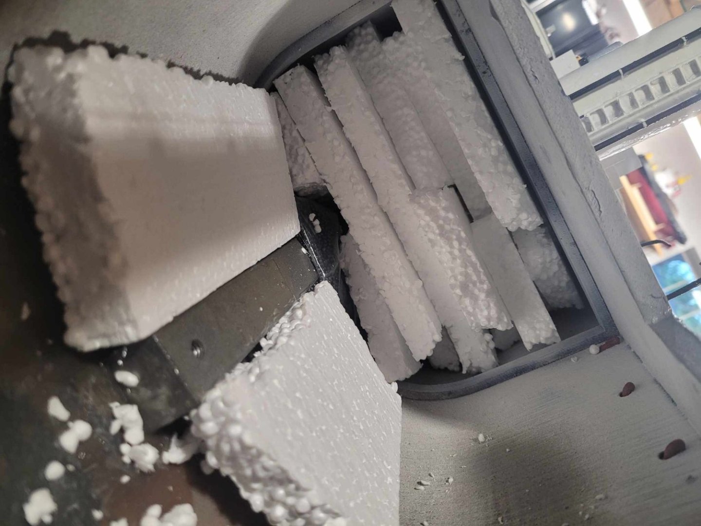
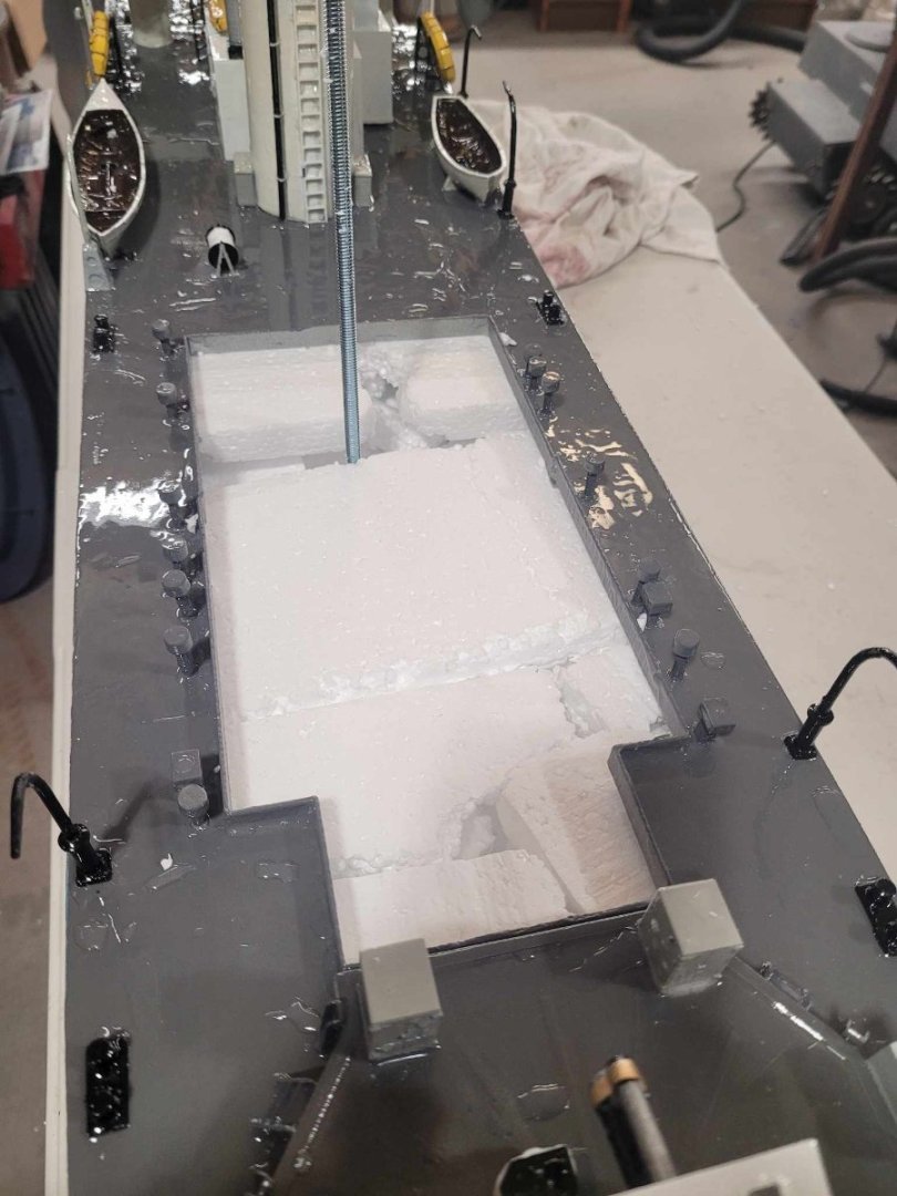
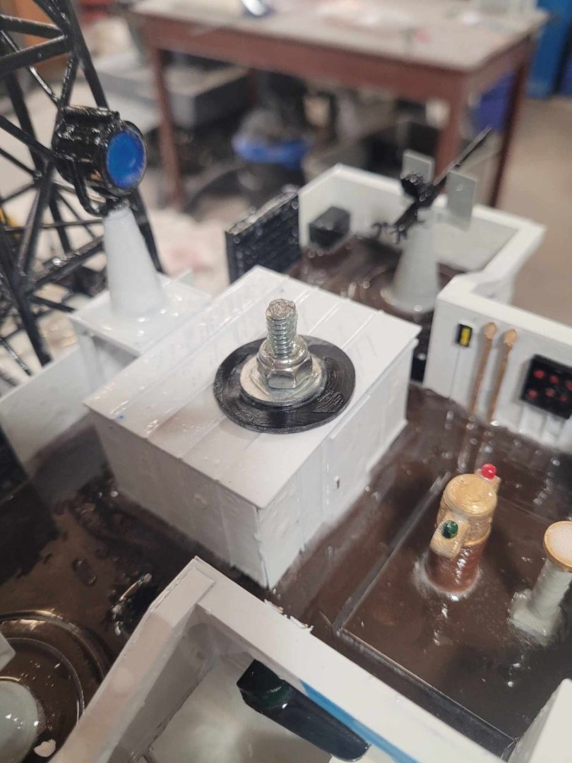
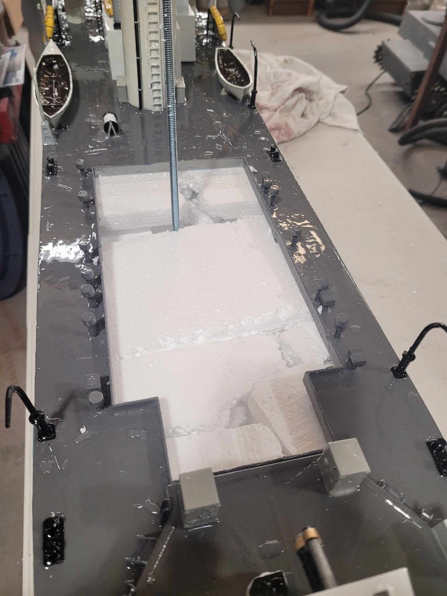
OK, here's the hull, stuffed with foam so she won't sink, with the threaded rod added and the nyloc nut on top holding the superstructure on!
- mtaylor, Canute, king derelict and 1 other
-
4
-
Here you see the drilled and tapped hole for the 1/4-20 threaded rod. I'll pick that up on the way home from work tonight along with some blue foam insulation to slice and dice and fit into the hull for floatation.
Second photo shows the 'bits' being held down after the layer of epoxy has been added. VERY pleased with the progress. A couple of days for the epoxy to cure and we'll be having a float test, and adjusting ballast!
- Canute, king derelict, yvesvidal and 1 other
-
4
-


HMCS Bonaventure by NavyShooter - 1/96 scale - an RCN fitting out
in - Build logs for subjects built 1901 - Present Day
Posted
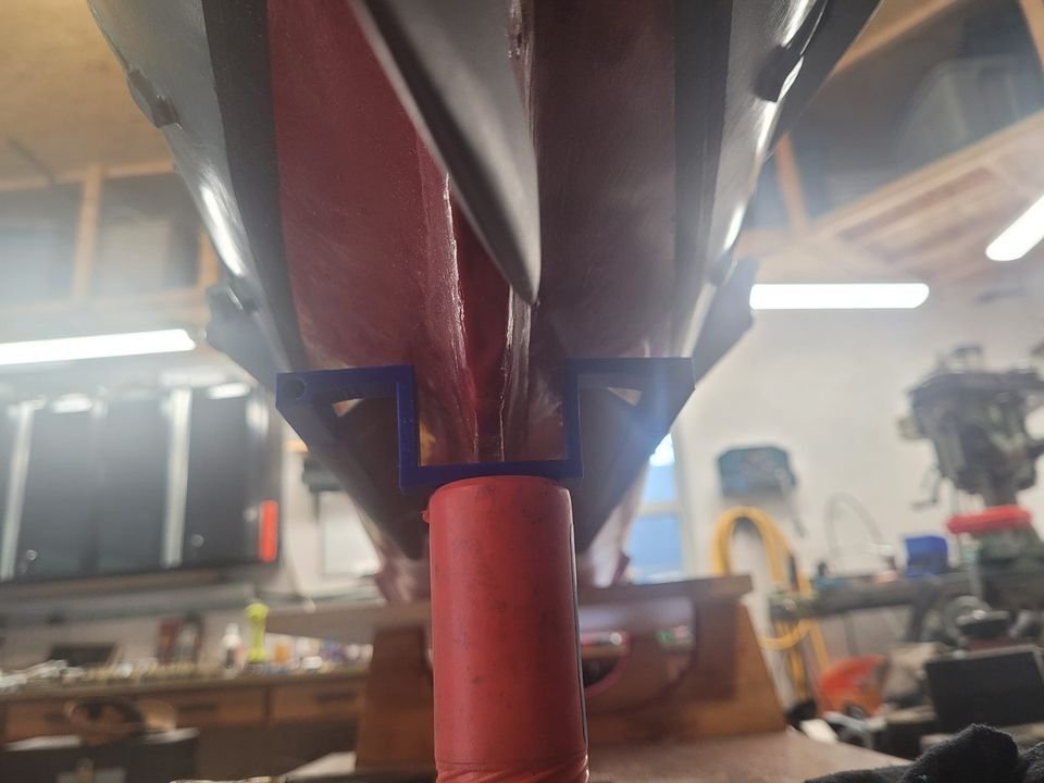
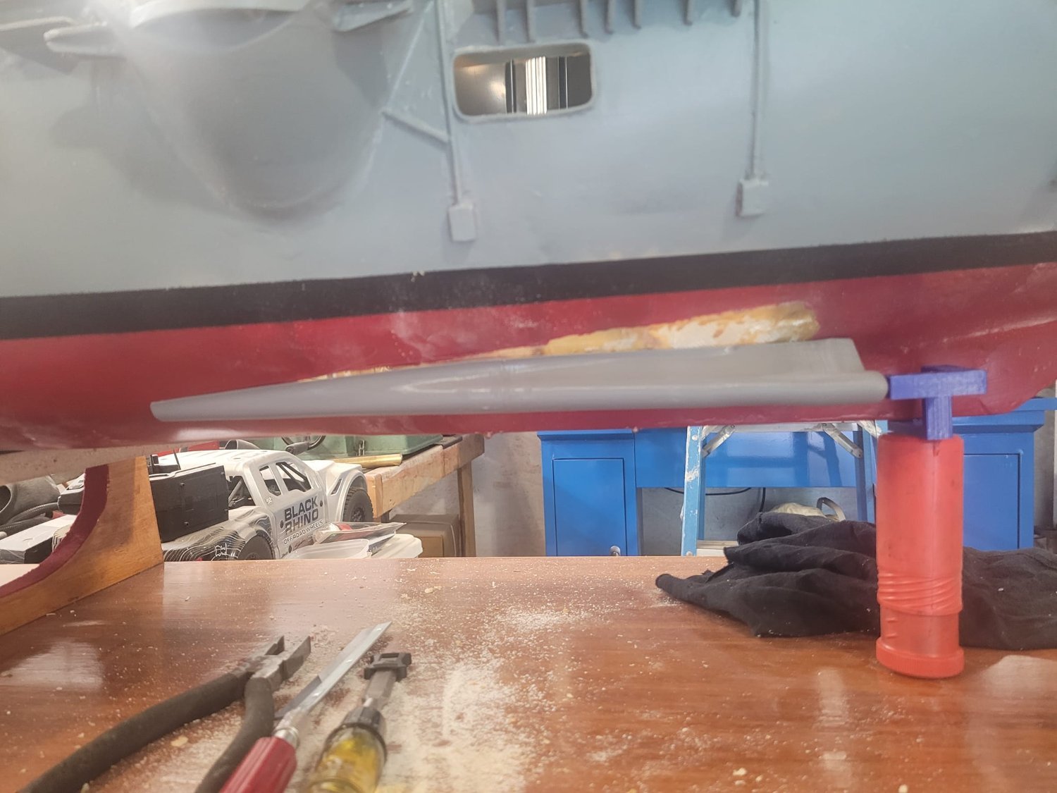
I also took the time this evening to put a layer of bright orange on the test target drone at last.
Came out pretty good I think!