

NavyShooter
-
Posts
594 -
Joined
-
Last visited
Content Type
Profiles
Forums
Gallery
Events
Posts posted by NavyShooter
-
-
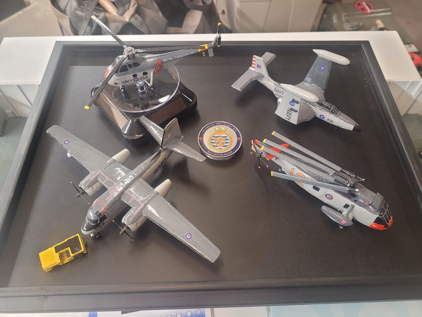
A couple of weeks ago, I came across a gent who has a display setup honouring the sailors from the Bonnie (and other veterans) in a local mall, so on Monday, I'm dropping off a 'mini' air-det to him, with one each Tracker, Banshee, Sea King and Horse. There is a glass cover for the display box, so they'll be protected (which is a good thing.)
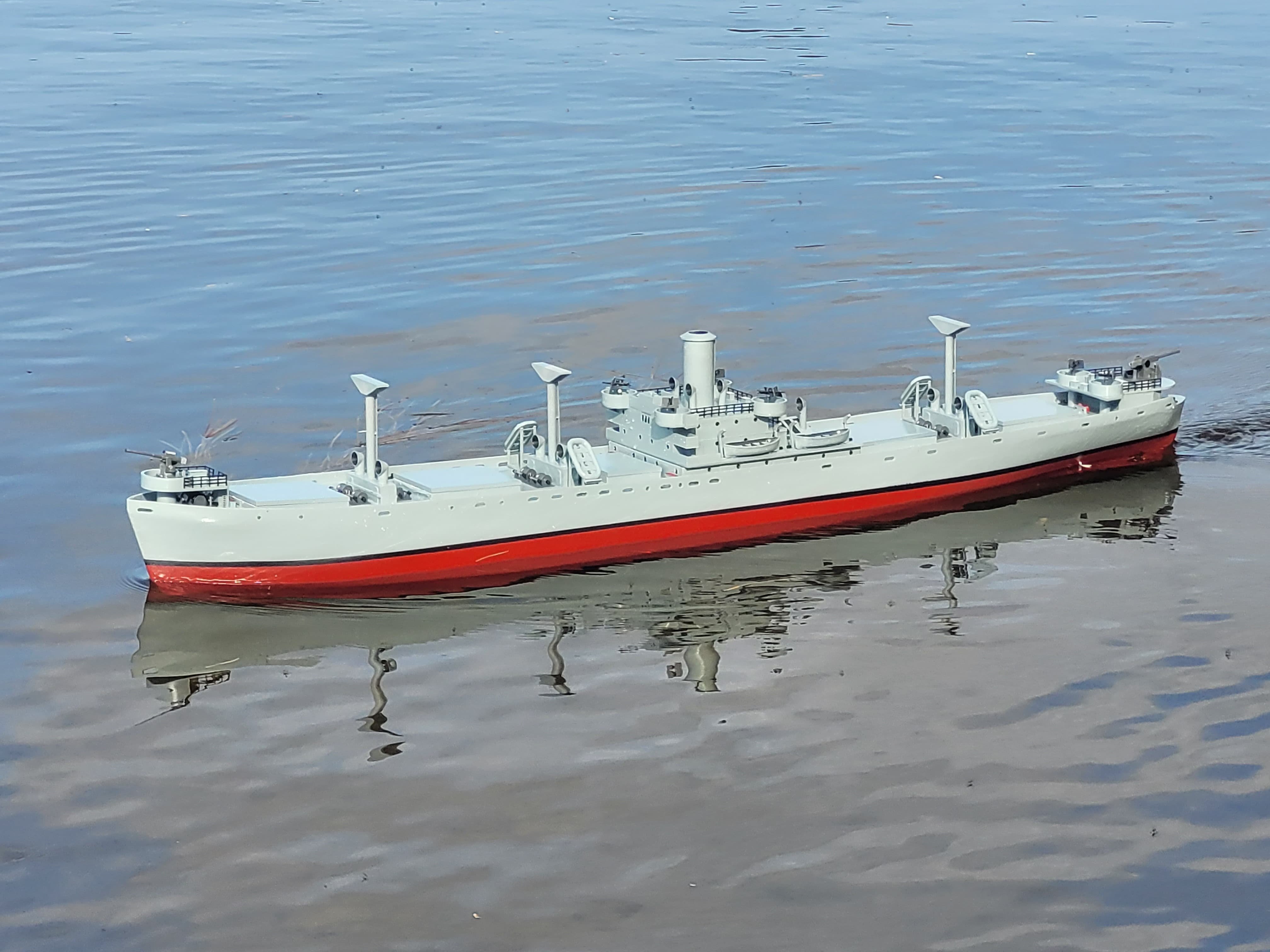
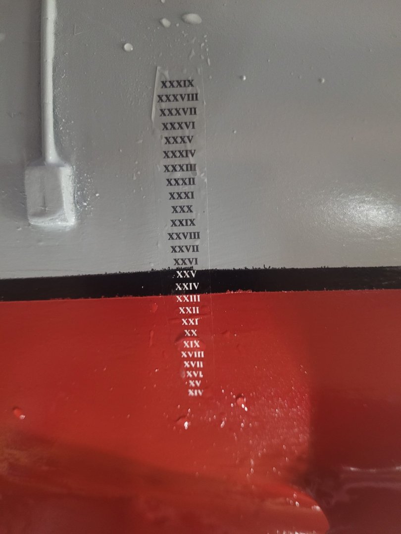
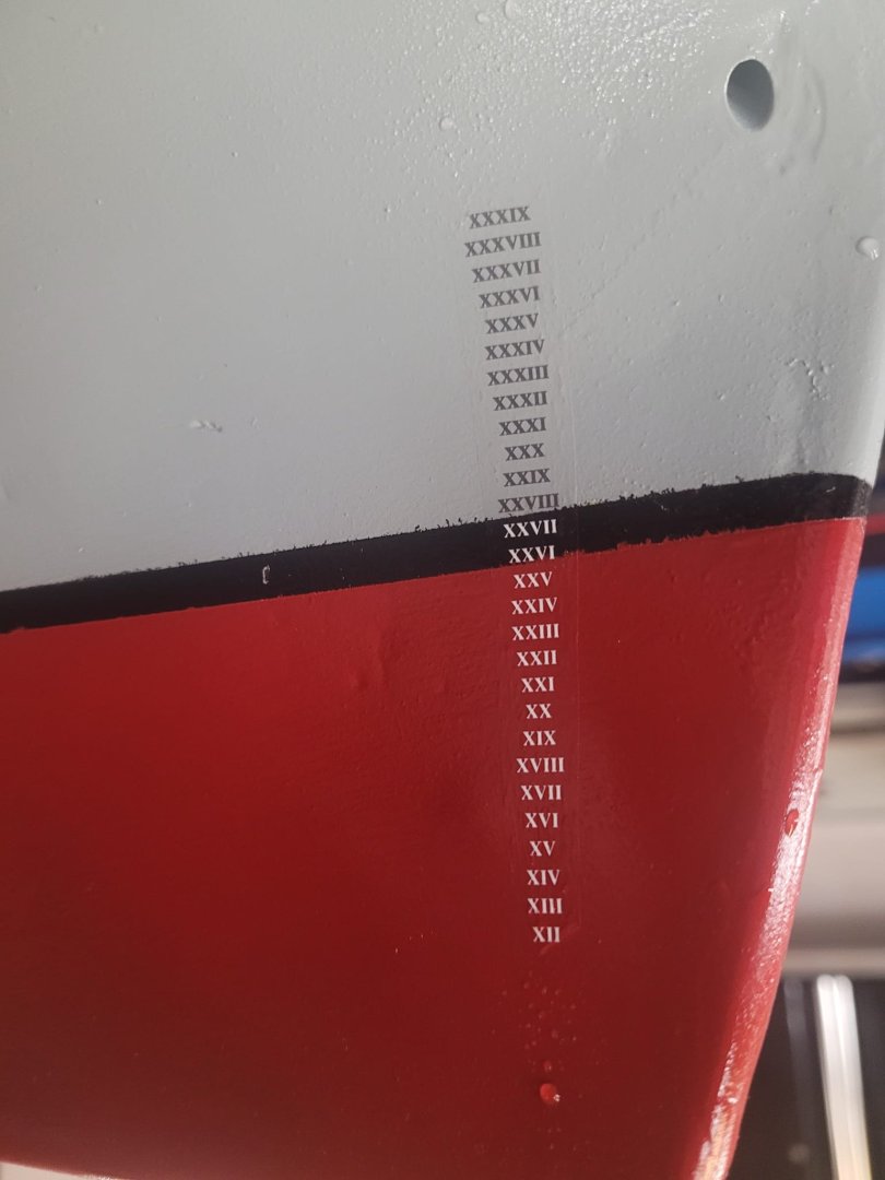
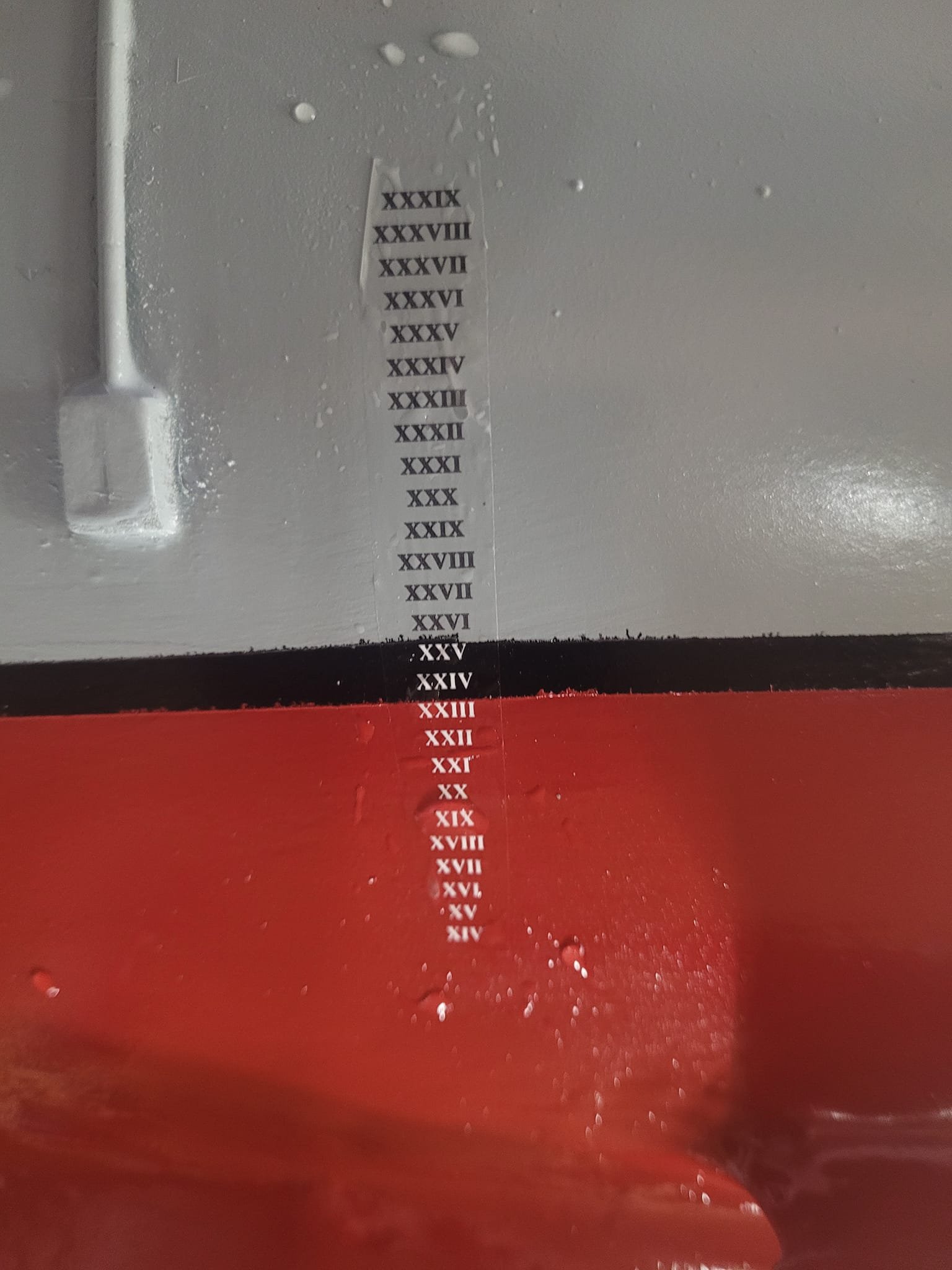
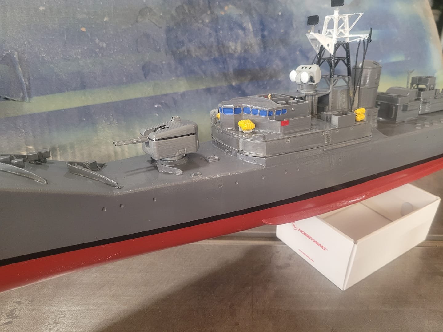
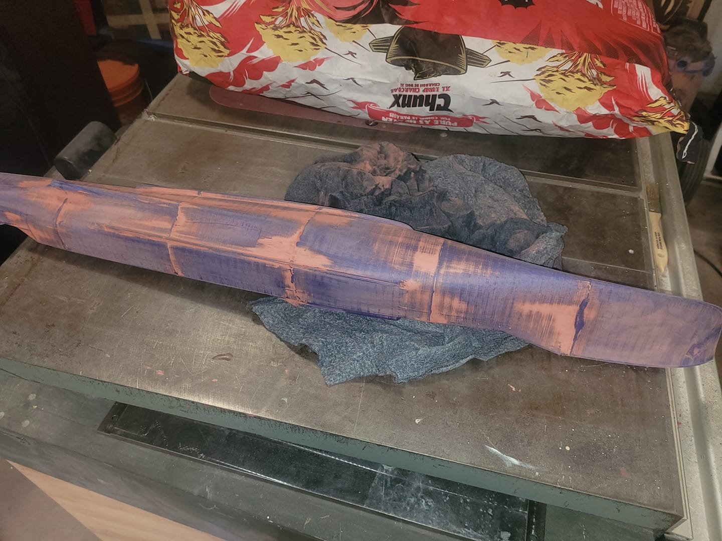
Also, the hull has now dried a bit, so I've decided to put the draft markings on. I'm quite pleased with how that looks.
Let that dry for a few days and I'll add a few layers of clear coat sealant on it to protect them.
- Keith Black, mtaylor, Haliburton and 5 others
-
 8
8
-
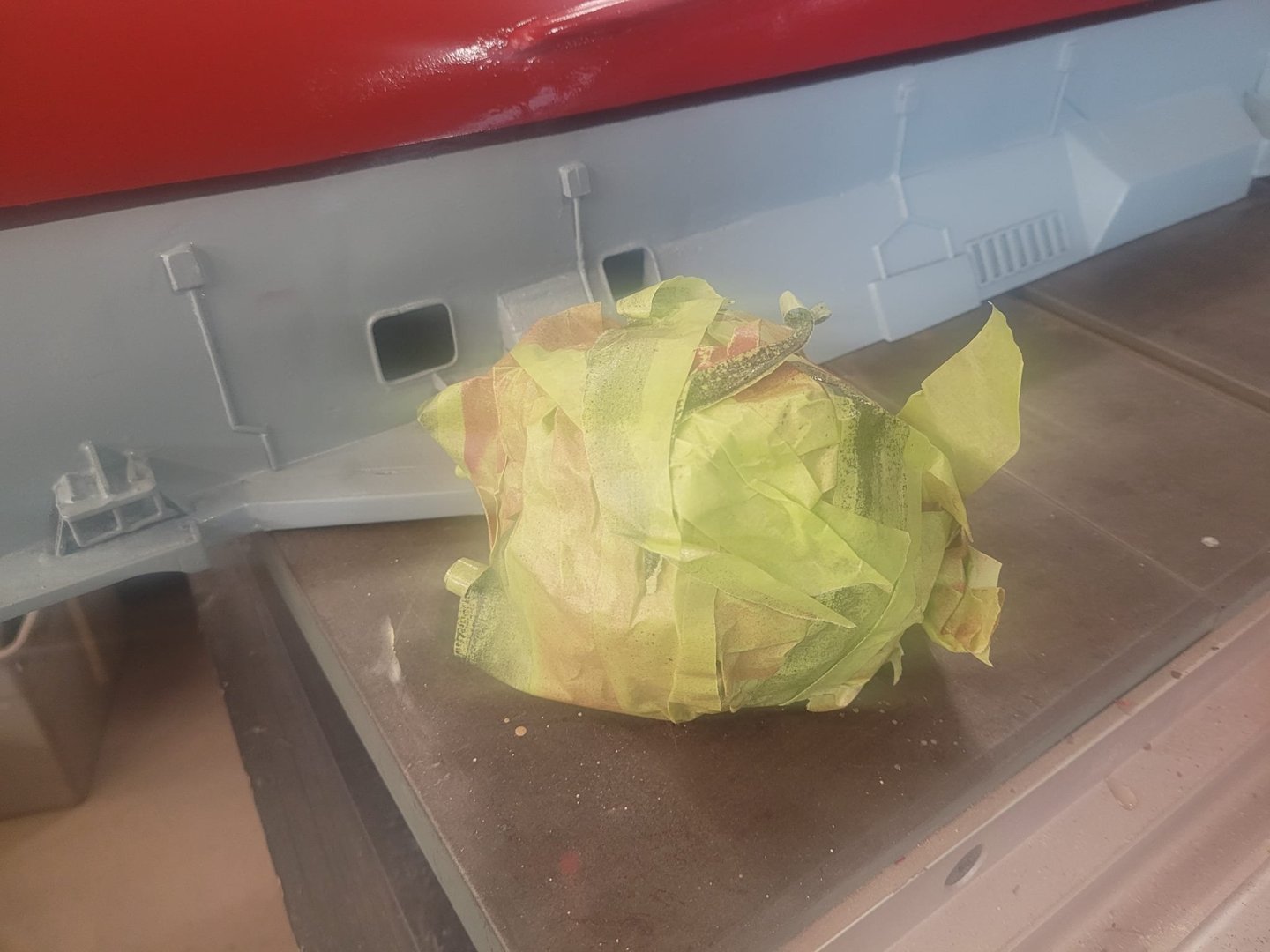
There's something really nice about pulling off that ball of tape...and seeing that nice clean boot topping...
- ccoyle, Canute, GrandpaPhil and 6 others
-
9
-
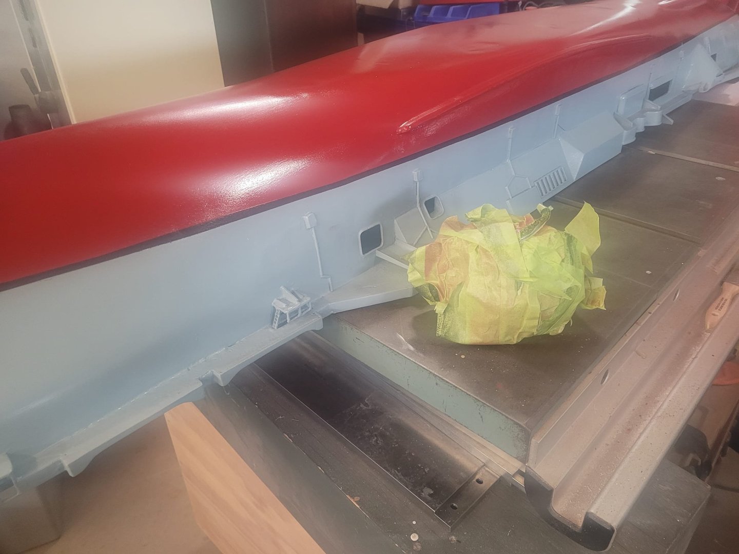
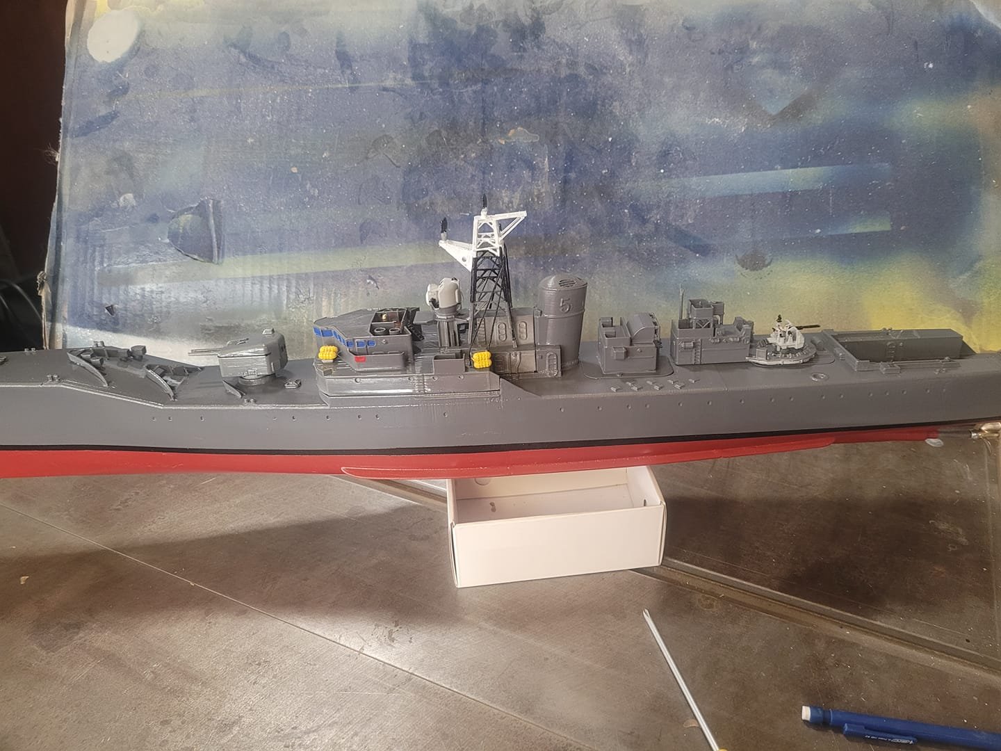
Tonight I was out in the garage puttering away at a few things - I masked up the boot topping, and shot the keel with the first layer of red. I'll let it dry a bit and shoot it again on the weekend probably.
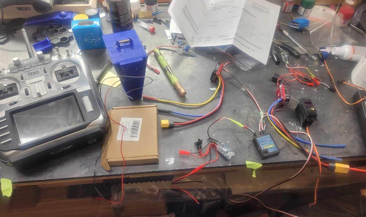
I was also puttering away with some electronic bits - once the keel is done and dusted, I'll be able to flip the hull over and start working on the guts...but wanted to get some work done tonight on some of the 'extra' channels on the receiver. I was puttering away at the Anchor Chain hoist system tonight. It's a bit finicky.
- Canute, mtaylor, Keith Black and 2 others
-
5
-
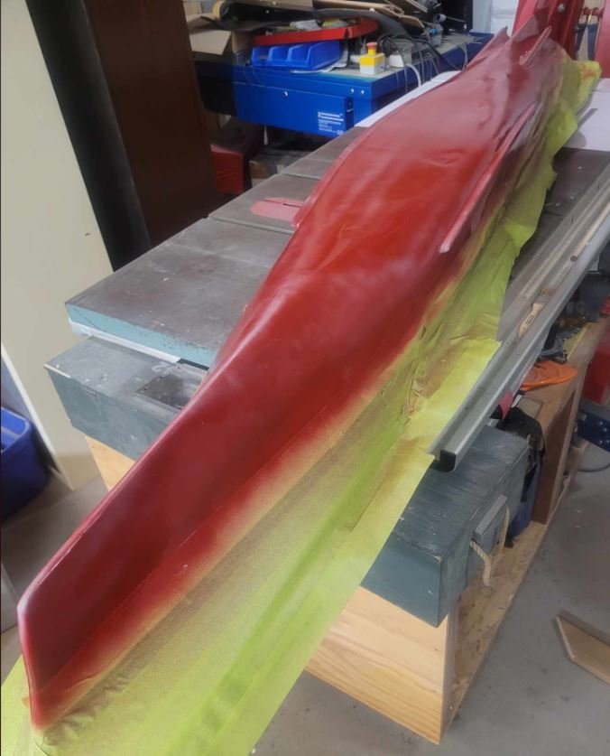
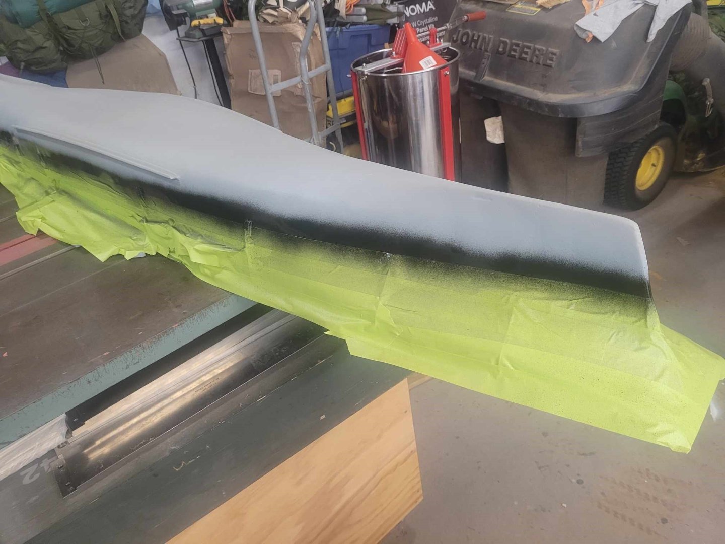
Hull has been masked, and boot topping applied.
Next will be to let this dry for a few days, then a strip of tape to cover the boot topping, and then the hull will be red by the weekend!

-
-
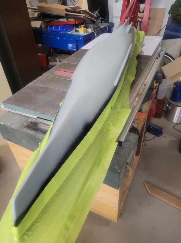
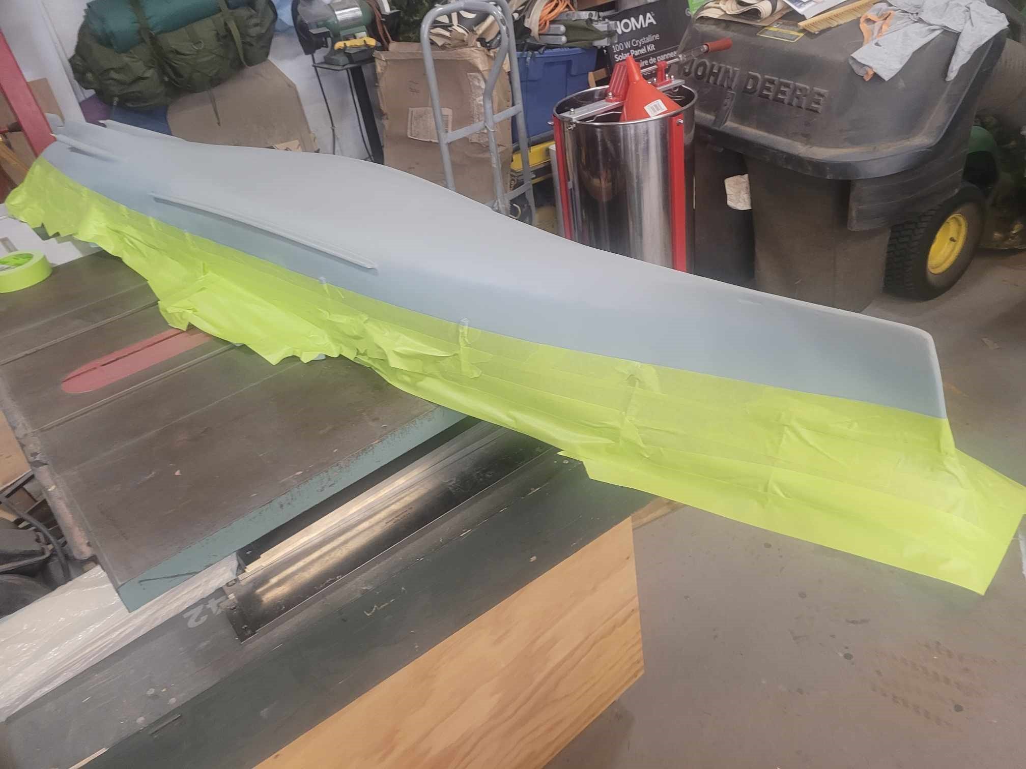
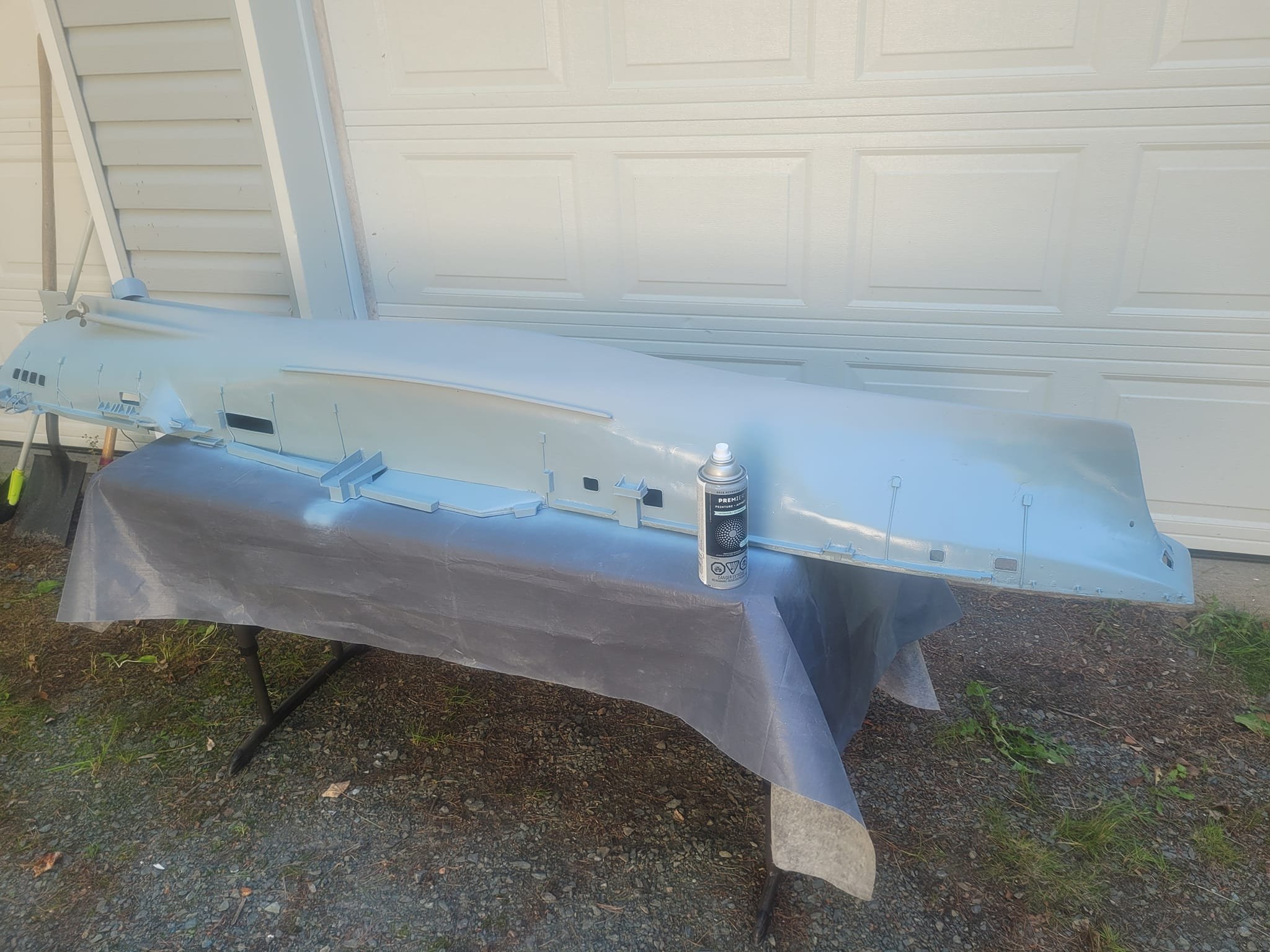
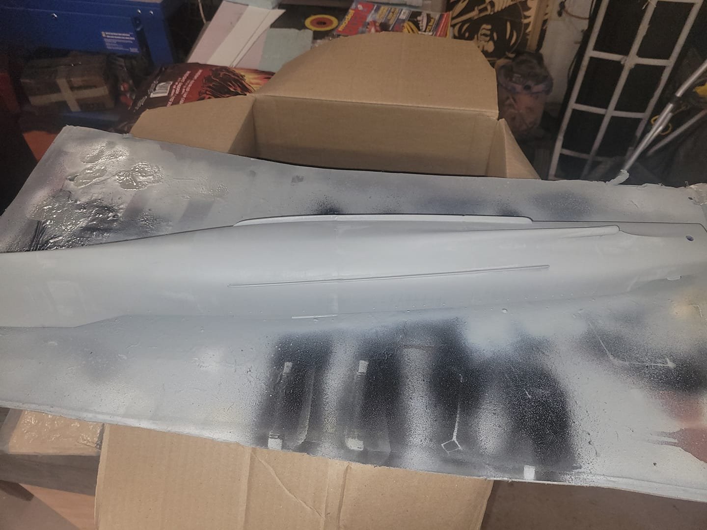
Here we go with a second layer of gray on the hull.
Next will be scribing the waterline, taping it up and doing some red, then the black boot topping.

- Haliburton, mtaylor, KeithAug and 4 others
-
7
-
Got caught up on some things last week, and this week I got back to some work on the Bonnie. The HMS Blackpool model is basically complete - just some minor details left to add/finish up, so This week I got the Bonnie out on the paint table, flipped her over and did the upper hull portion in gray paint. Next step will be to scribe the waterline, mask, then do the red.
We'll see how that goes!
- Keith Black, Canute and mtaylor
-
3
-
Great work! The window must have been frustrating to fix, I'm glad you were able to figure that out in the end. The paint looks outstanding!
-
On 8/14/2024 at 12:01 PM, ddp said:
why did you do a single prop instead of a duall prop that the class was designed for?
Propulsion Y-100 plant; 2 Babcock & Wilcox boilers, 2 English Electric steam turbines, 2 shafts, 30,000 shp (22 MW) https://en.wikipedia.org/wiki/HMS_Blackpool_(F77)
You assume that I have a greater level of skill in 3D design than I actually have...taking someone else's 3D model and adjusting it to delete one shaft, and add 2 in place is not a trivial task.
My goal from this was to see if this was a simple workable 3D print that I could use for a 3D printing course as it is.
It's mostly OK for that. With the caveat that yeah, one shaft vs 2.
-
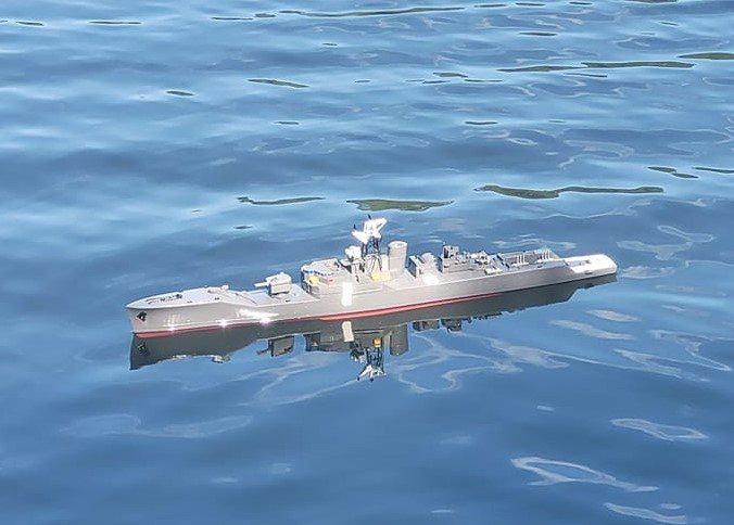
OK! Float test went well! I used some white tape to seal a couple of the upper deck hatches down on a temporary basis, and my 'temporary' prop shaft solution is, truly, only temporary. I was able to get out 20 feet under power, then things stopped working - such is life. Brought her back alongside.
The battery pack was all the weight needed to get her ballasted down properly.Generally pleased with the look. We'll see how she performs once I get things fixed up next week.
-
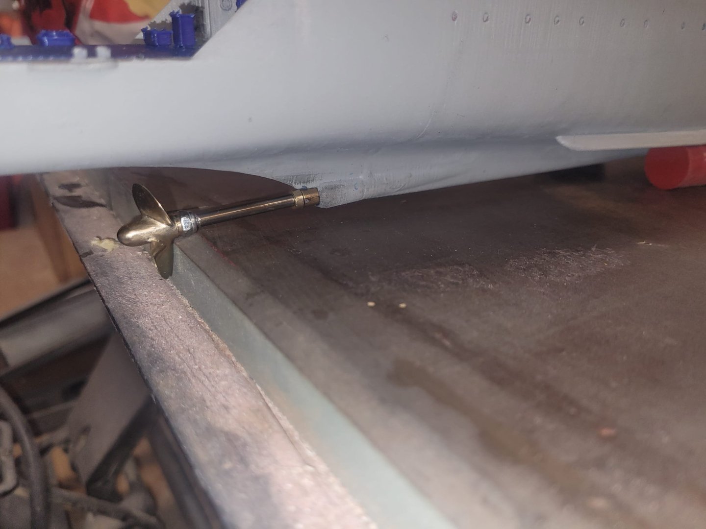
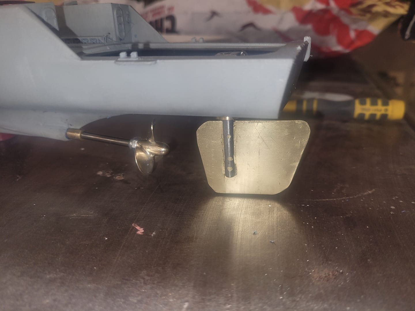
OK,
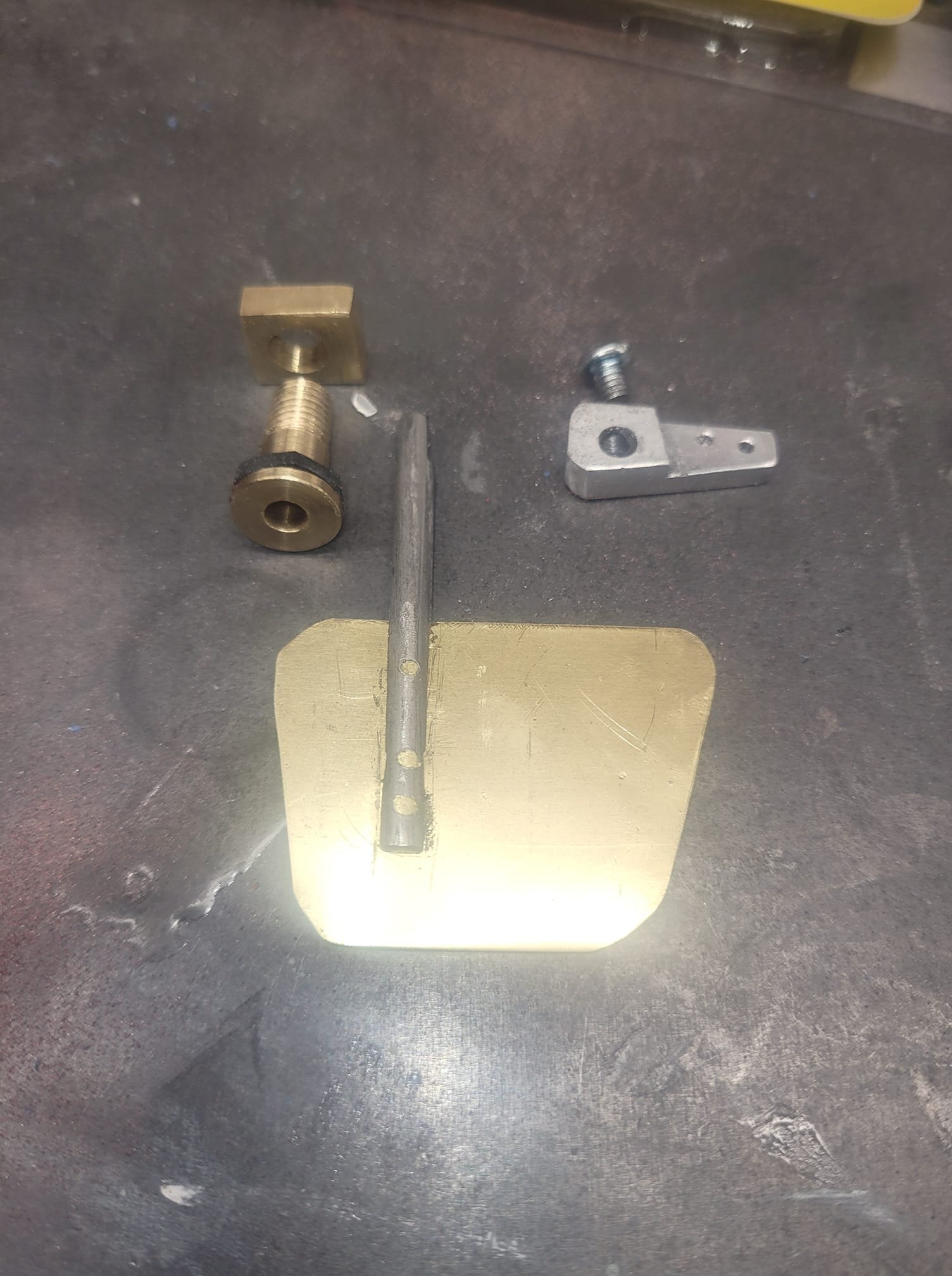
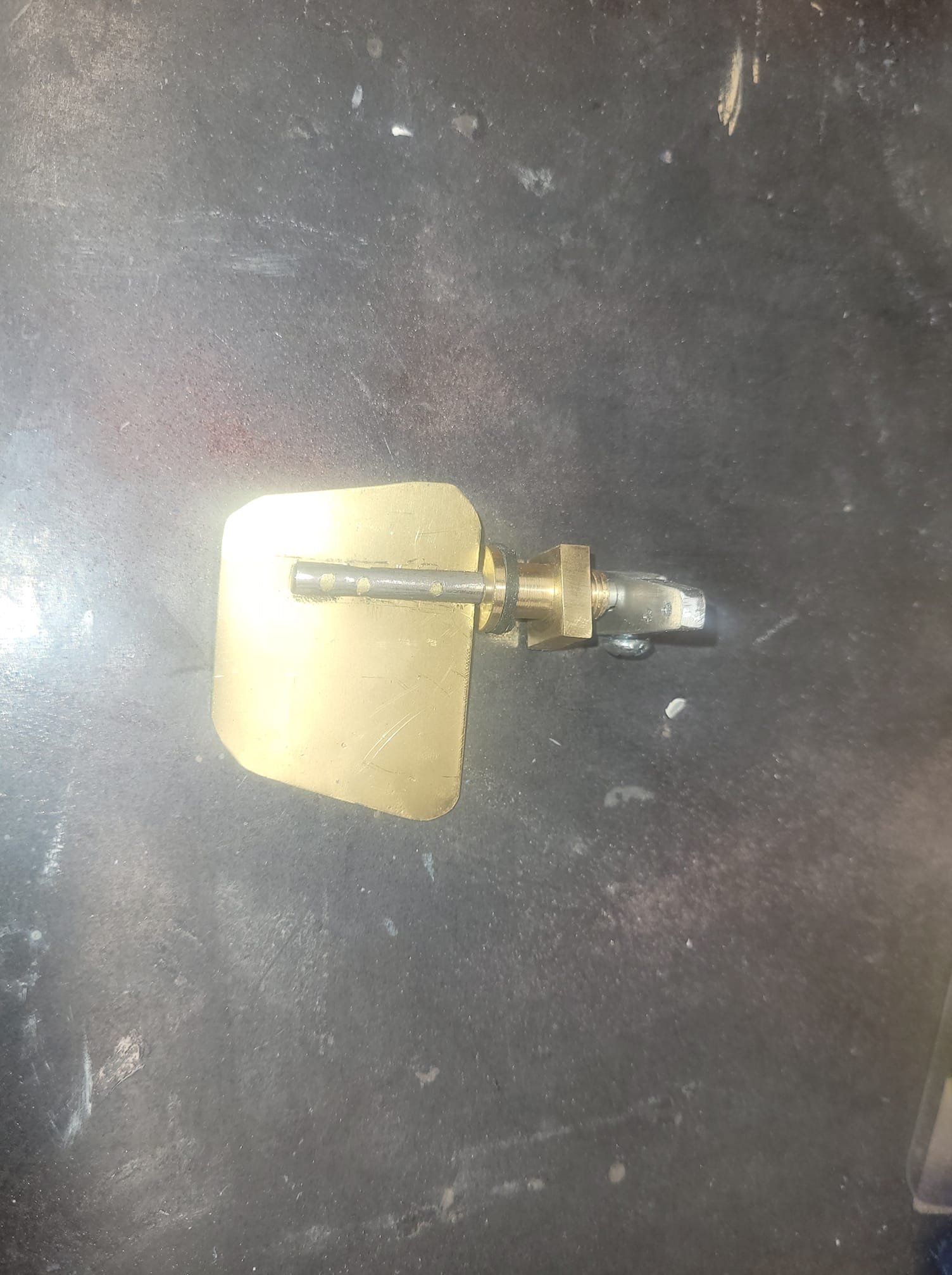
A temporary solution for the prop shaft is in place - the rudder works, prop will spin. Ish.
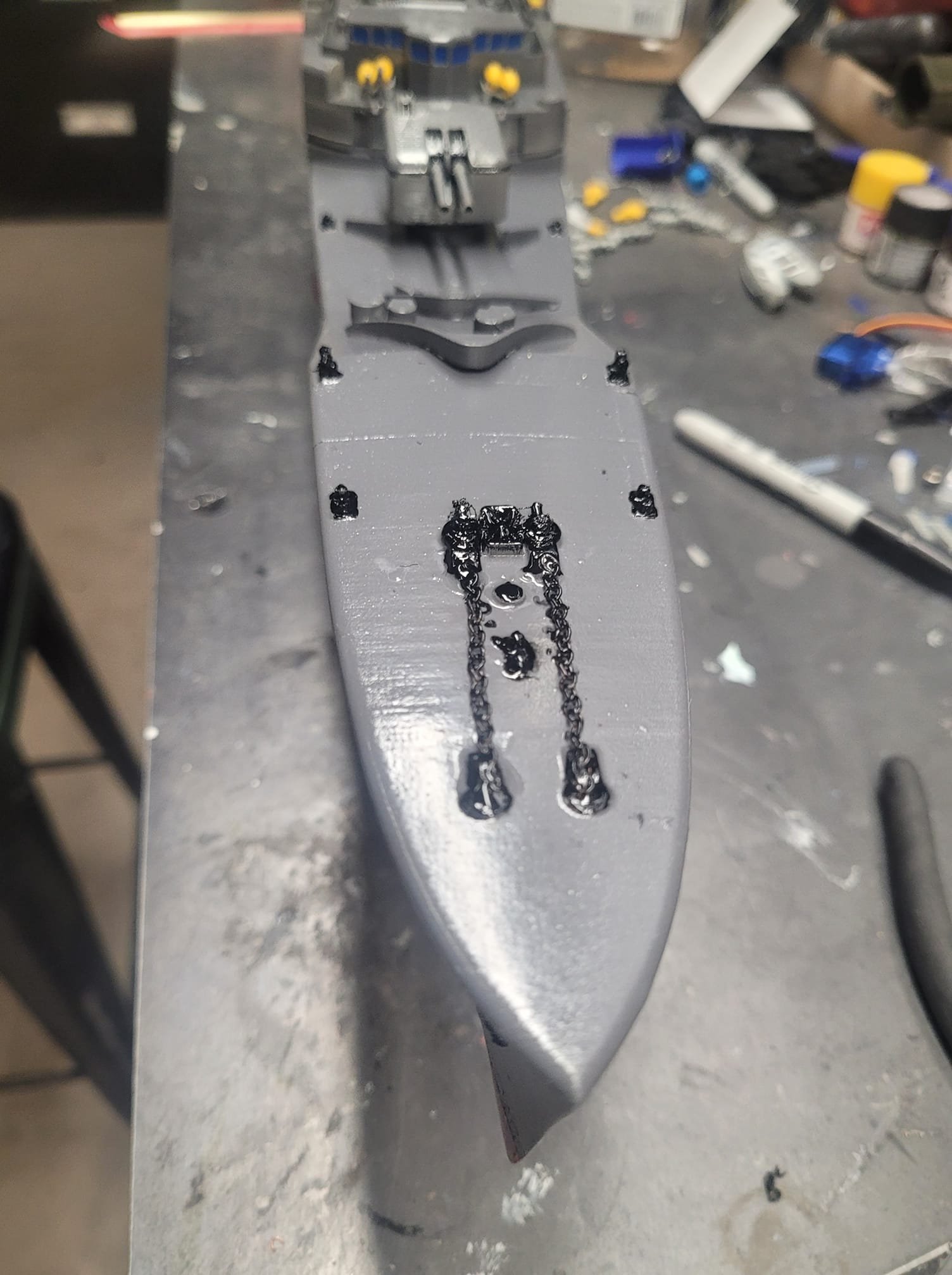
I did a bit of detail painting tonight, added some foam for floatation, charged the batteries up, and I think we'll see how she looks on the pond in the morning.
Oh, added a couple sections of Anchor Chain on the foc'sle as well.

-
-
Boot topping added - looks alright!
Assembled the RC side of the house - I needed a servo-arm pin/swivel thing and grabbed that at the LHS on the way home from work. Got the rudder setup and functional first. It seems to track OK.
Then I decided to try and dial in the shaft line and install the motor - and....well...let me observe that the shaft line piece I had and used isn't perfectly straight it would seem...so while the motor is in, the shaft is too stiff in the stuffing tube to be spun freely. It is VERY Sticky.
Good news is that I have a new shaft coming in the mail, and according to the Royal Mail tracking system, it's in Canada...we'll see if I get it tomorrow or not. -
Got home late last night after doing some enjoyable things on a range with the Army folks I work part-time with, and ended up doing a few minutes of light (220 grit) sanding on the hull, and a light overspray of the dark gray paint again. I think tonight I'll end up putting tape on and spraying on the boot topping, then tomorrow I'll start putting on the last details and getting her assembled and ready for the pond on Saturday.
-
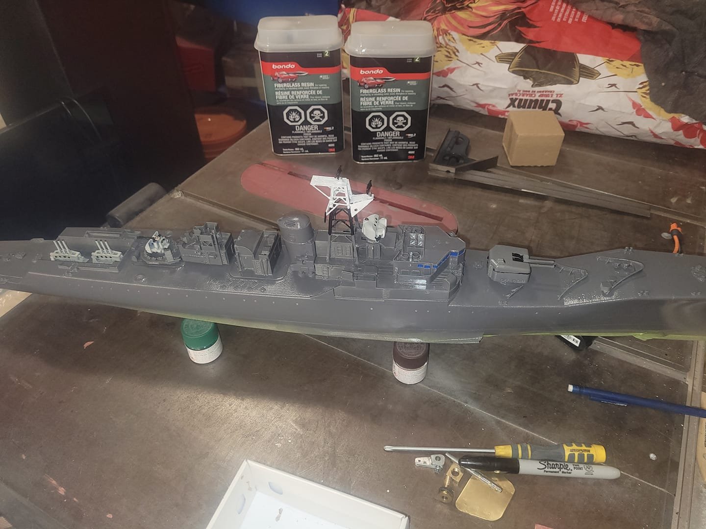
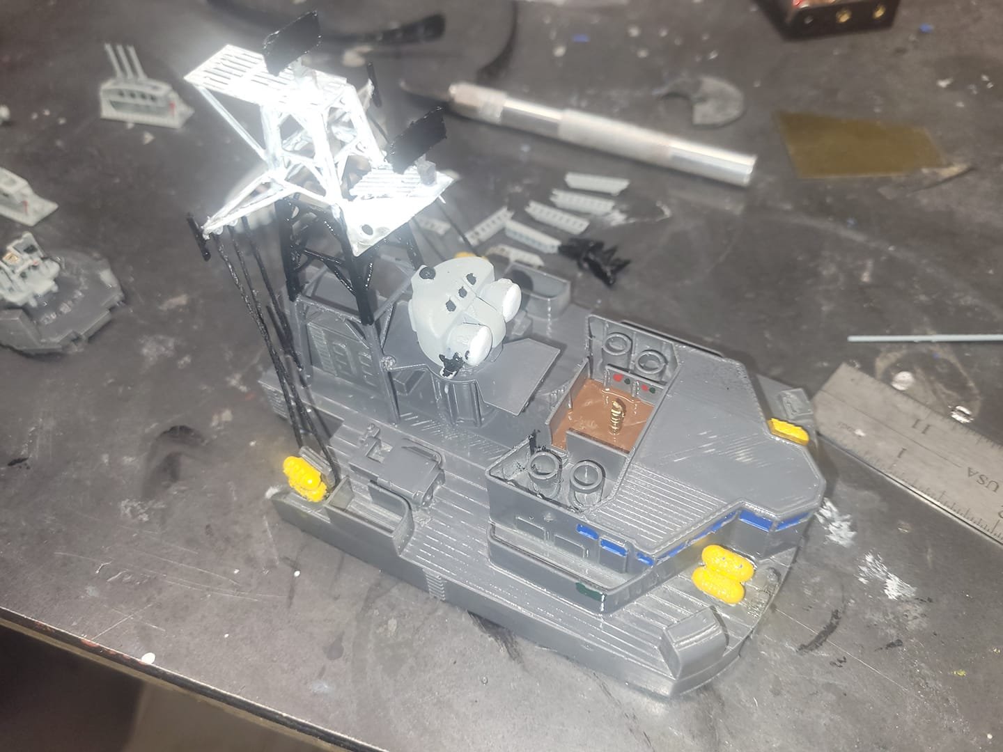
And....here we have some dark gray applied for paint. I know it's not quite right for colour, but, it was what I had onhand, and it's a different gray than what I put on my RCN ships.
I did some basic rigging on the superstructure as well.
Generally pleased with how she looks.
-
-
Correct! The print file was setup for a single shaft.
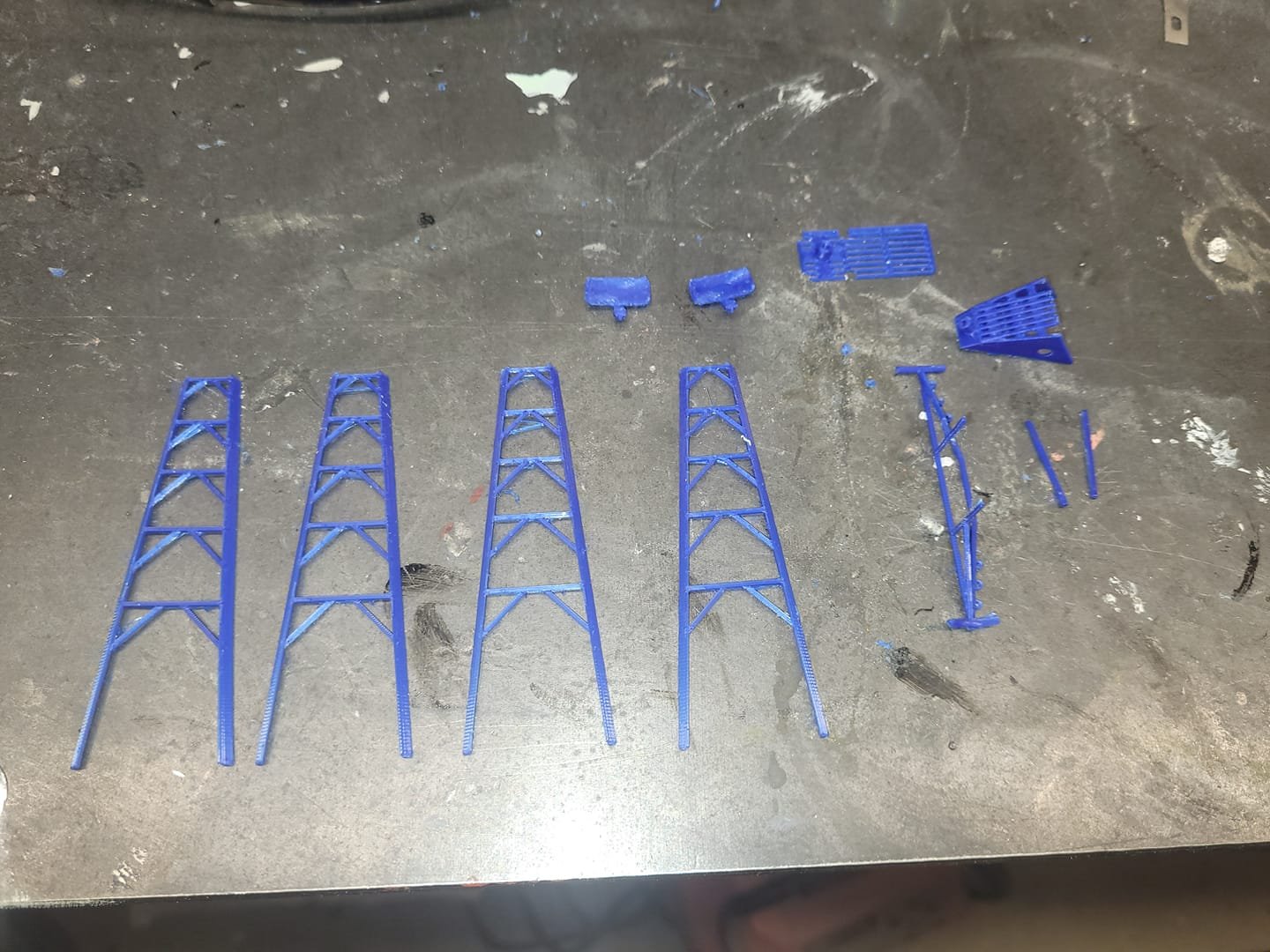
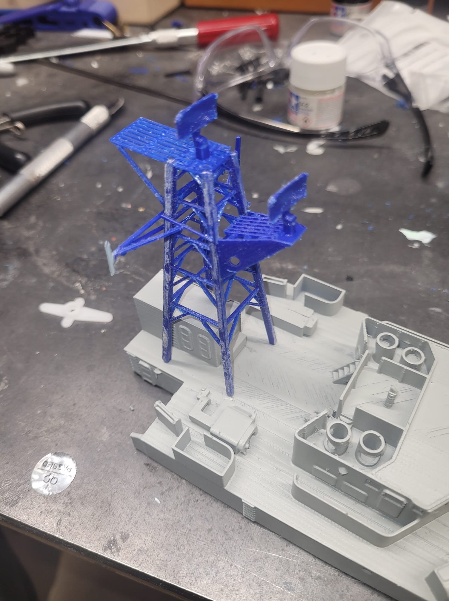
Today I built up a 3D printed mast based on the smaller one from my Bonnie model. I added a Yardarm with some full dipole Antennas and used a Radar dish from a Gepard AA tank model. Turned out OK methinks!
It is not 100% accurate based on images, but it's close enough for this project.
NS

-
-
-
10 hours ago, Kuparu said:
Greetings NavyShooter,
I am watching your build with interest and, if i may, a degree of caution. I built a 1:96 model of the same class of frigate some years ago, in fibreglass with a variety of suitable materials for fitting out above the main deck. She has two motors and shafts with scale 5-bladed props, a large battery pack and only three channels of r/c. Overall weight is about 3.15kg. I found that I had to take every measure possible to reduce the top-weight to get her into a stable condition and she is still a problem with rolling during the turns. The fitting out of the foremast took particular attention with weight minimisation.
I look forward to seeing your tank test/maiden voyage next weekend. Good Luck, Kuparu.
I will do my level best to keep upper deck weight low! I've picked up a small battery pack to keep that weight down, and I'm using 9g servos as well. Overall printed weight is quite low. We'll see how things turn out!
My plan for the mast will be 3D printing as well - I'm hopeful that will keep the weight down there as well!
-
-
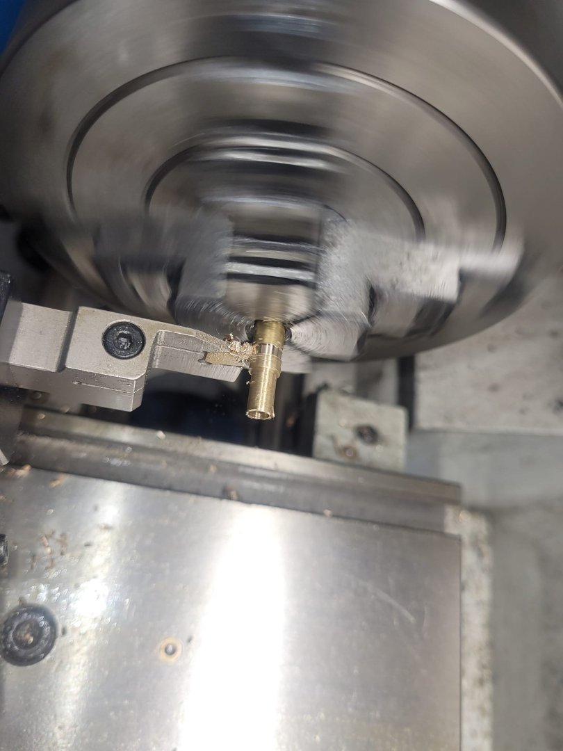
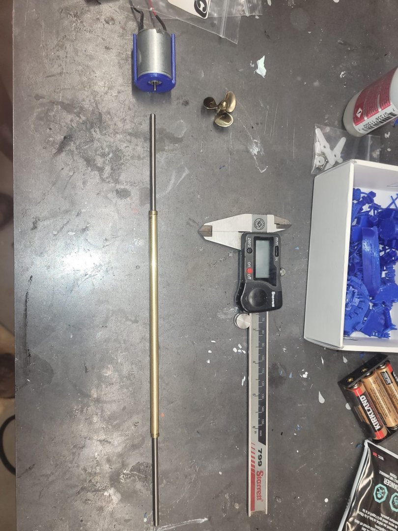
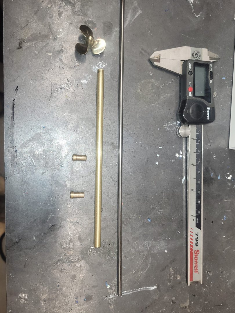
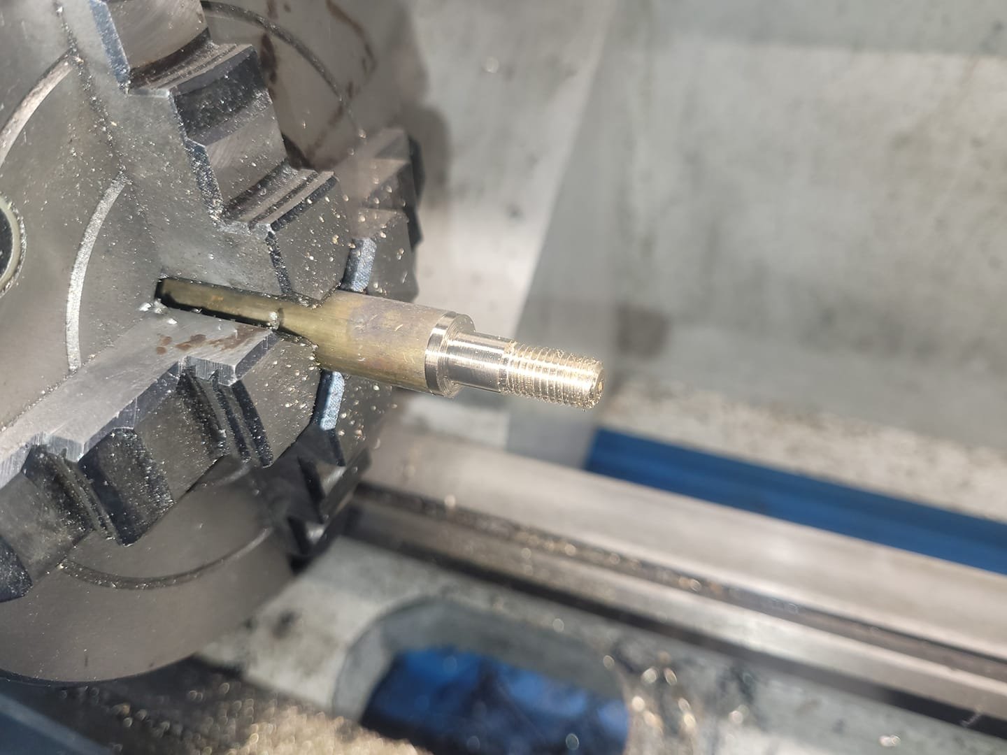
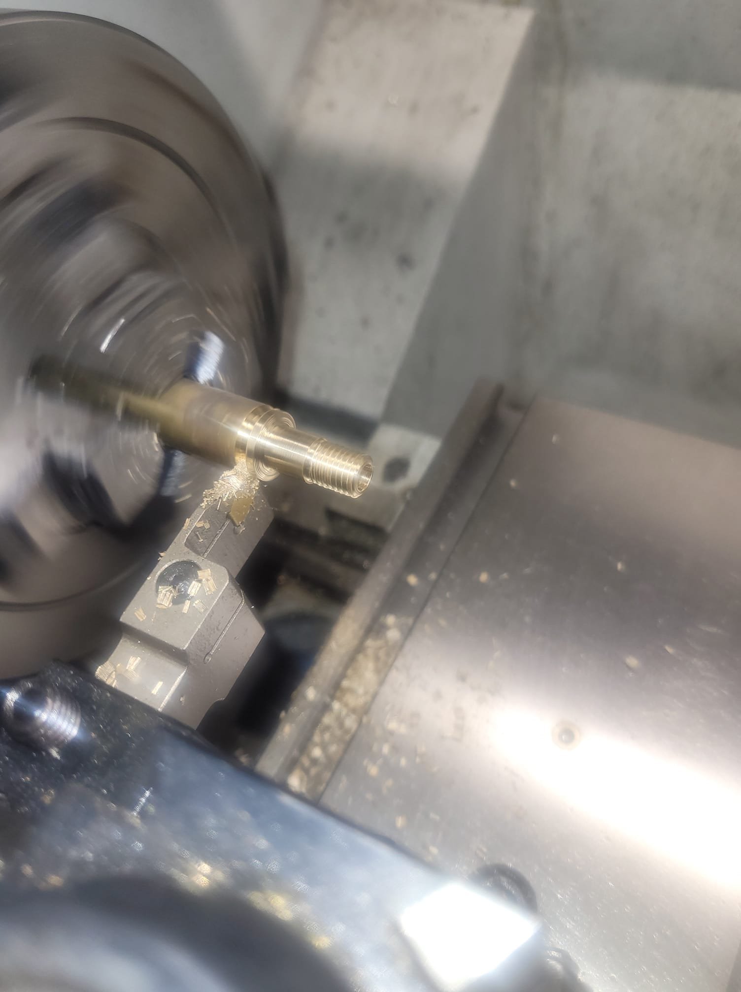
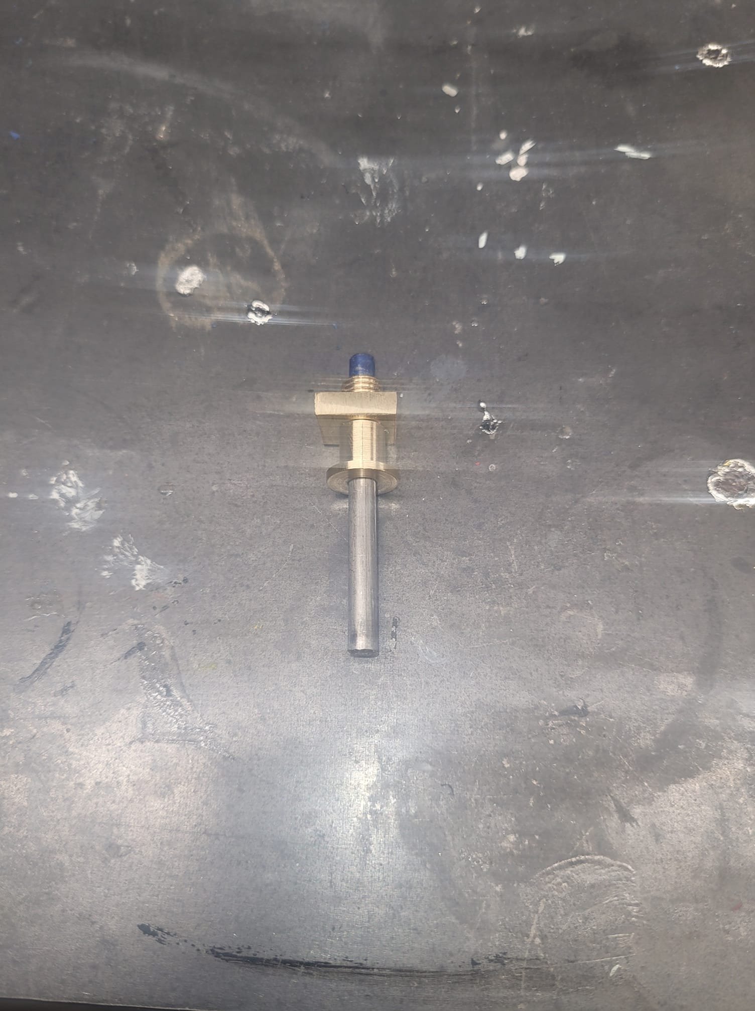
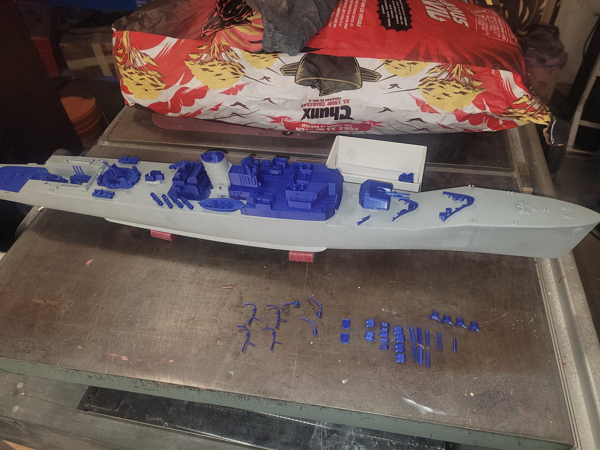
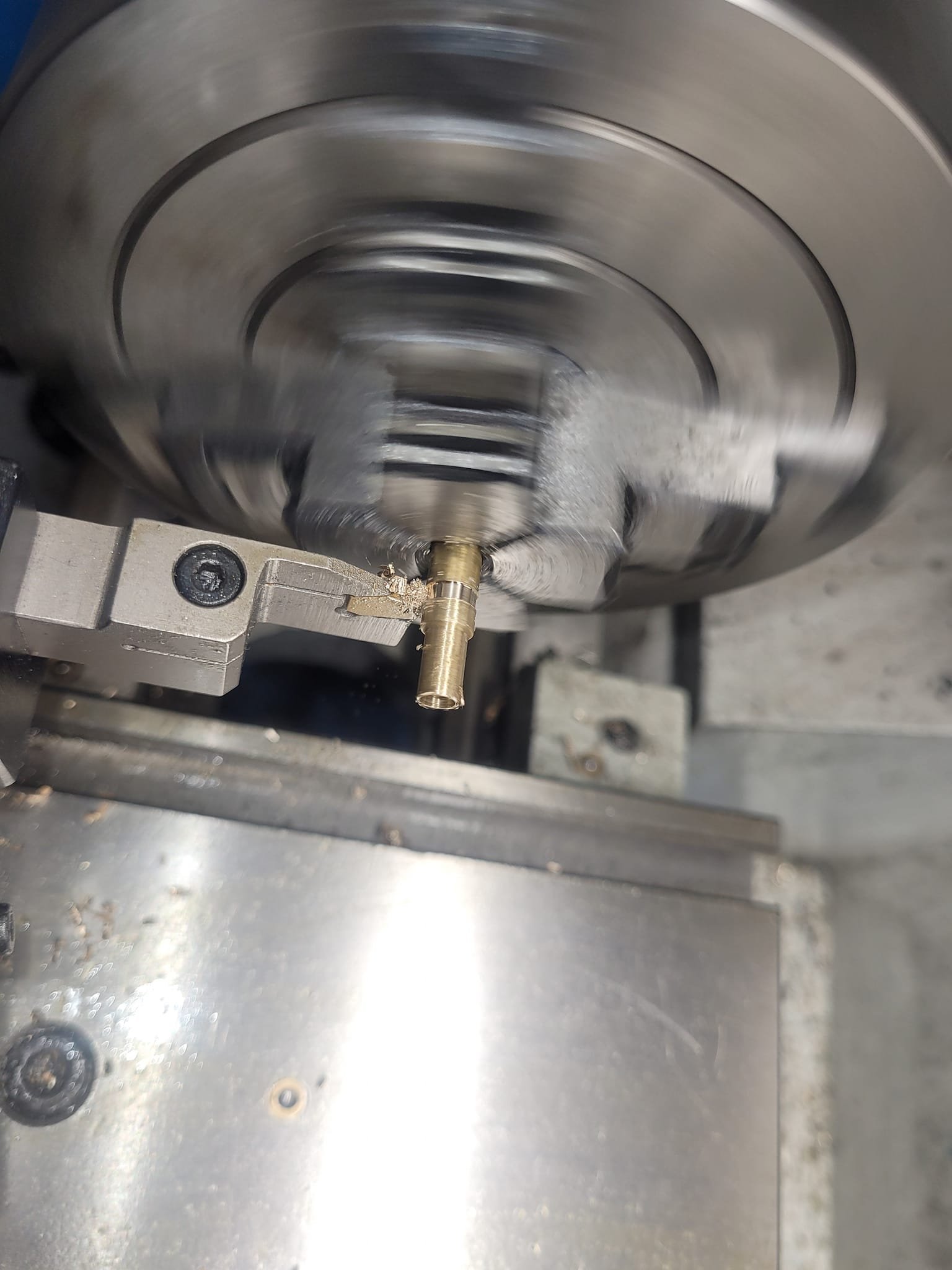
All the printing is now complete. I've got 'intentions' to get the ship in the pond next weekend for testing. Now, that said, I have only just ordered the prop shaft from the UK on Thursday...so...I decided to see if I could spin something up that might suit the role.
-
-


HMCS Bonaventure by NavyShooter - 1/96 scale - an RCN fitting out
in - Build logs for subjects built 1901 - Present Day
Posted
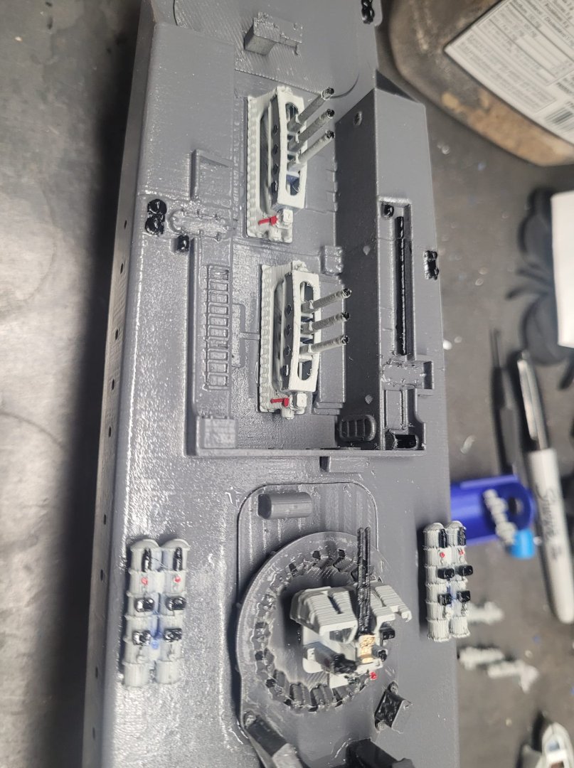
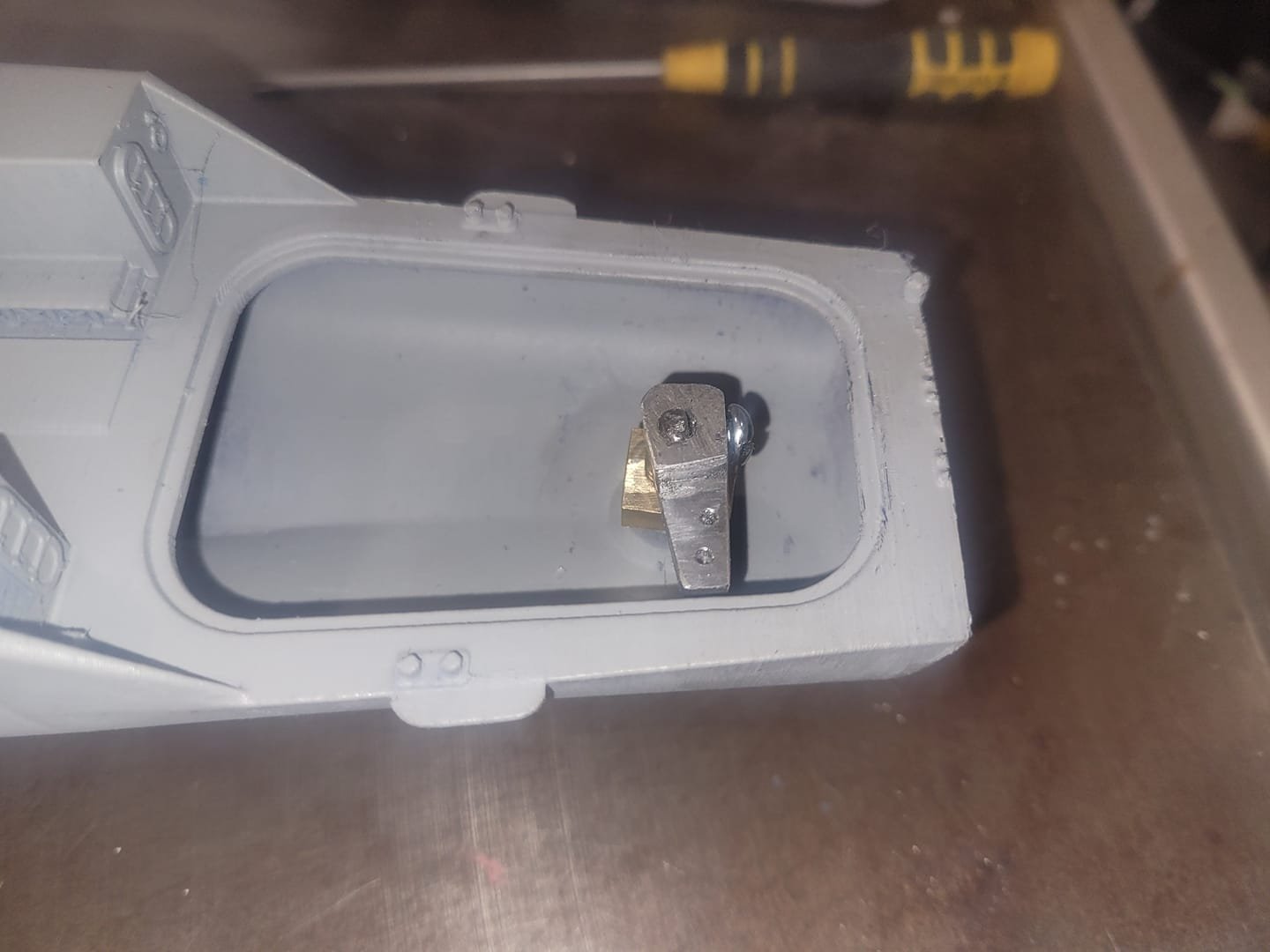
So this afternoon I had a few minutes to invest in working on the Bonnie. I've got the large opening in the flight deck for the hangar module done, now it' s a question of having access to the rest of the interior bits I need to get to.
So, here's the entry hole for the rudder post/servo area cut out. It's also the space where I put in the workshop spaces that I 3D printed - so - I have to be able to remove them through this hole.
It all fits and works.
Observe the use of the post-it notes to setup the edges of the hole for cutting - I put the post it notes on the hull to line up where I wanted the edge to be on the flight deck, and then instead of measuring/transferring the hole dimensionally, I simply put a post-it note over top of the lower one, aligning the edges perfectly.
If it looks stupid, but it works...is it really stupid?